individual assignment
parametric design and 3d printing
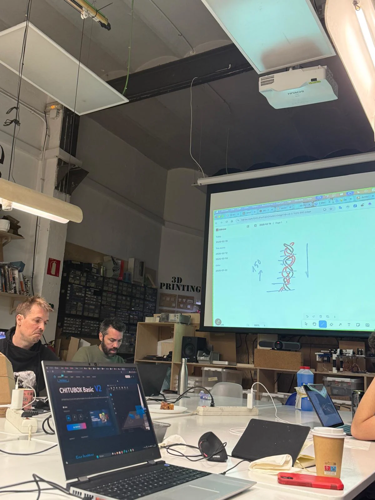
for this week's assignment, I used rhinoceros and grasshopper to parametrically design a chainmail that I could 3D print on the X1Carbon.
Chainmail is a series of interlocked rings. It is impossible to make it subtractively from a solid block because the interlinking would require the tool piece to go underneath the surface, which is impossible with machining. They would have to be made separately and then linked together afterwards by having an opening on the side of every ring.
By 3D printing, the rings are created in layers so they can be interlinked as they are formed. 3D printing also removes the necessity for an opening on every ring and creates a chainmail that will be stronger as a result.
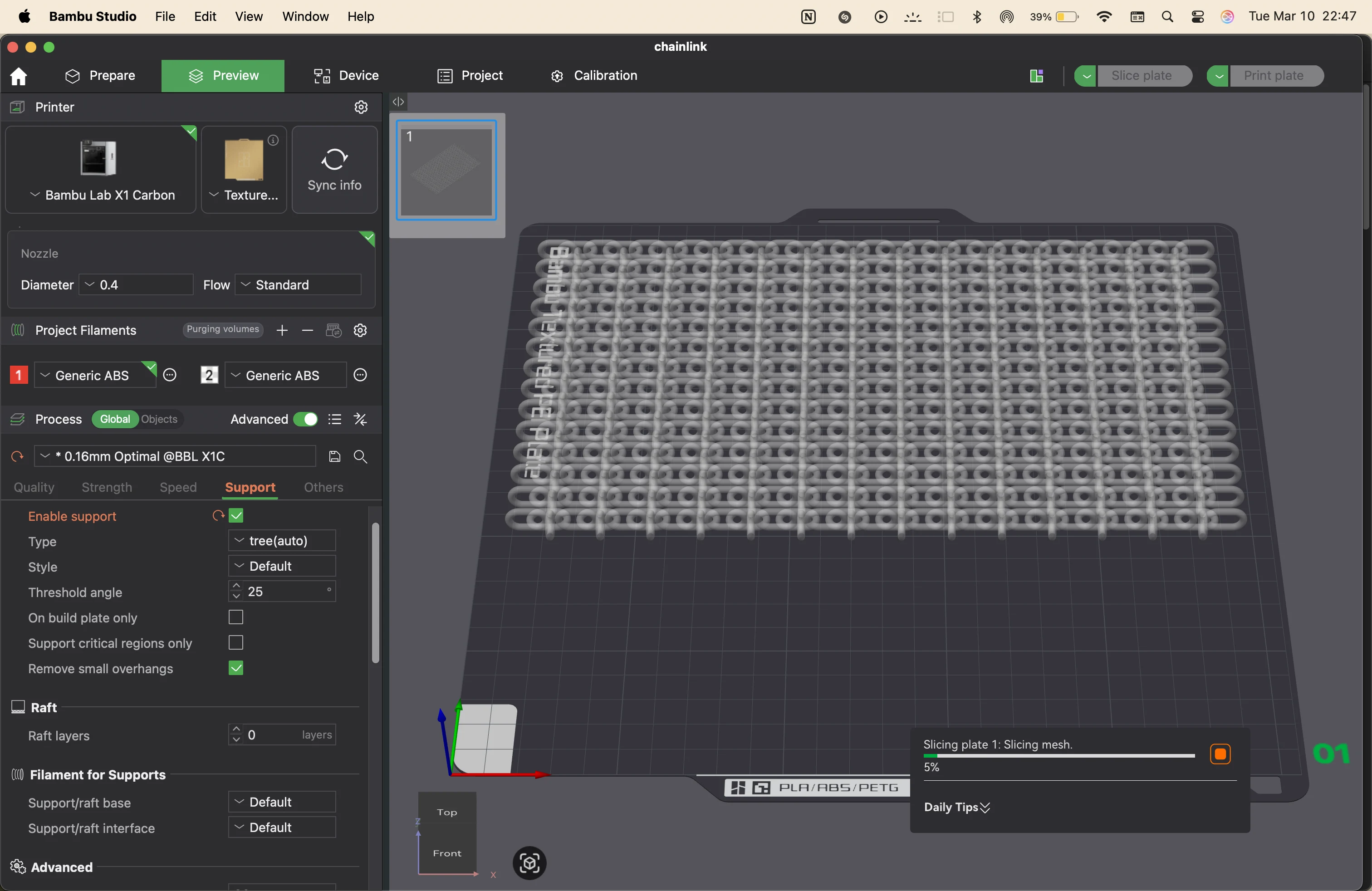
It is important to consider that a lot of support was needed to print every sheet of chainmail, and since the height is small, almost a third of the material gets used as supports. Supports are necessary to form the links and make sure the links do not get smooshed and connected to each other.
The finishing process is also added to remove the supports and clean up the model. This can damage the model unless the supports are loosely connected to the chainmail.
There are benefits to 3D printing it, and it is something that cannot be made in a single go in a subtractive manner, and it might take multiple subtractive steps to reach this point. But there are also drawbacks, like the use of supports, extra material, and that at this point it is made of plastic, while original chainmail is made of metal, which inherently becomes stronger as a material. But this can be a great alternative for costumes and props.
The process adds a lot of benefits in case we can eventually 3D print with metal. We already do, but at a bigger scale.
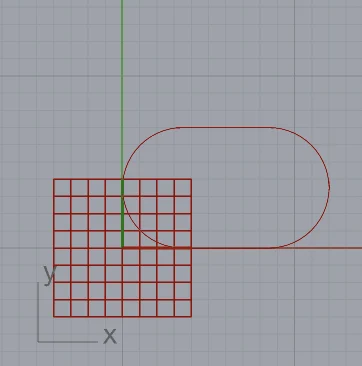
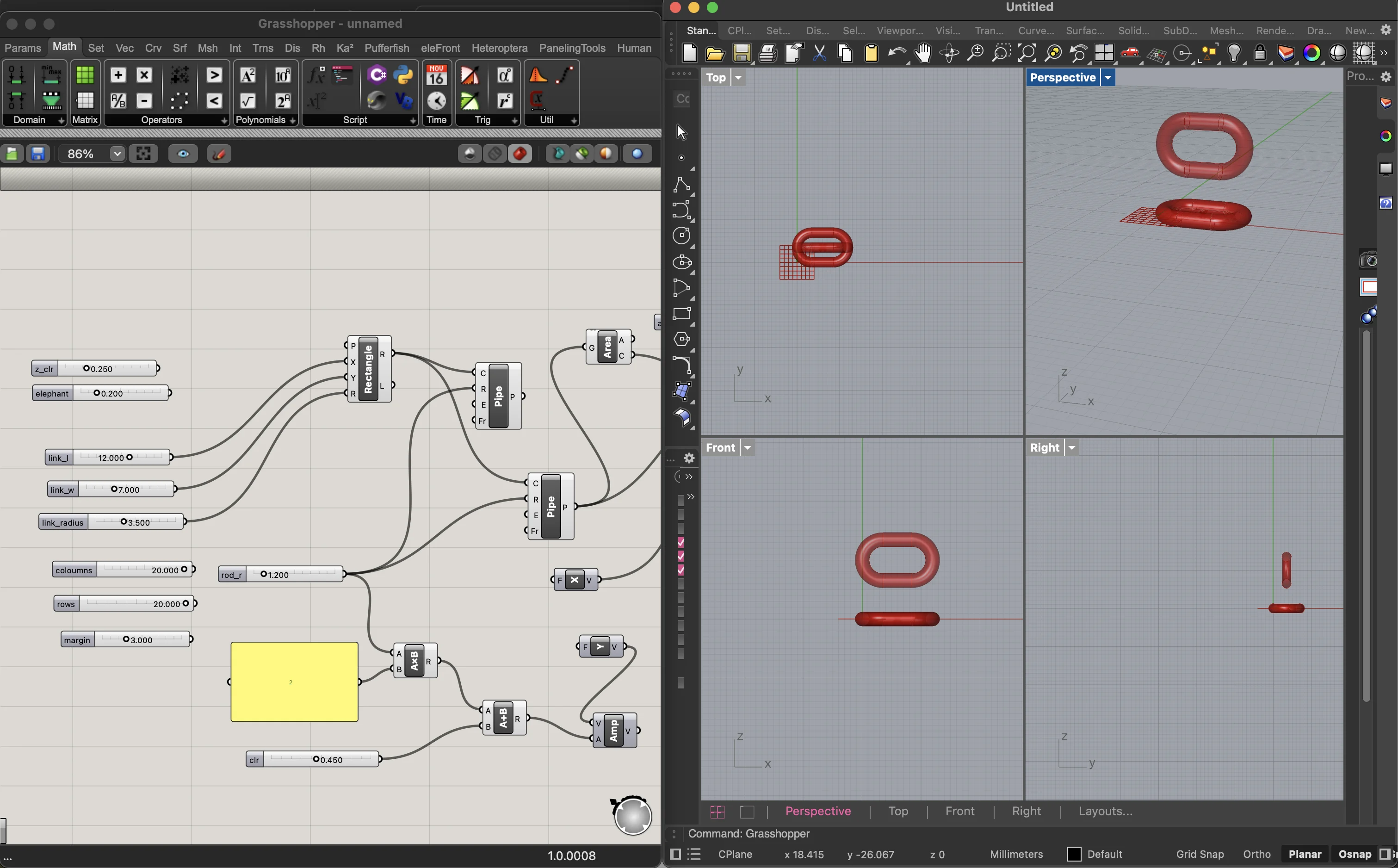
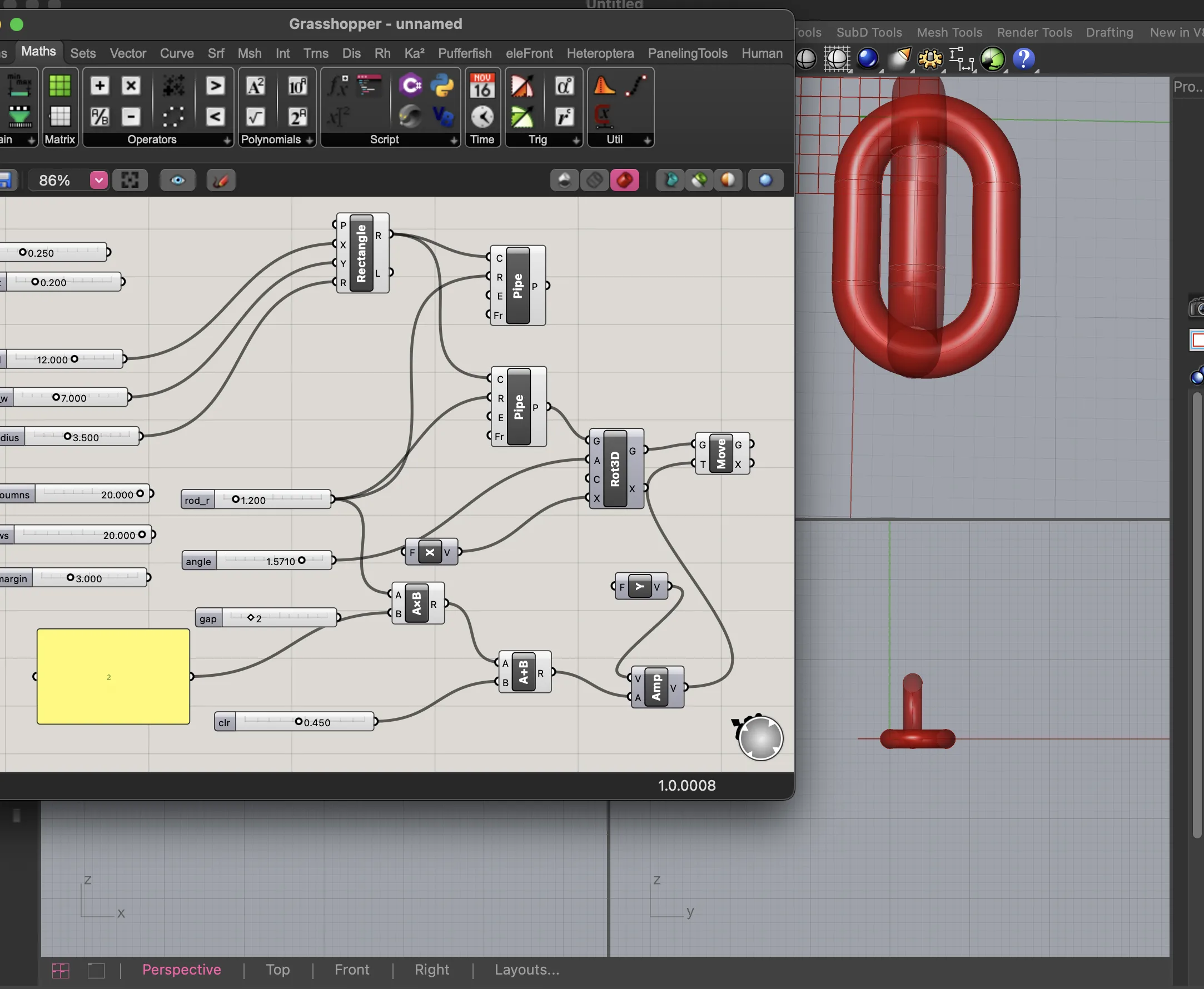
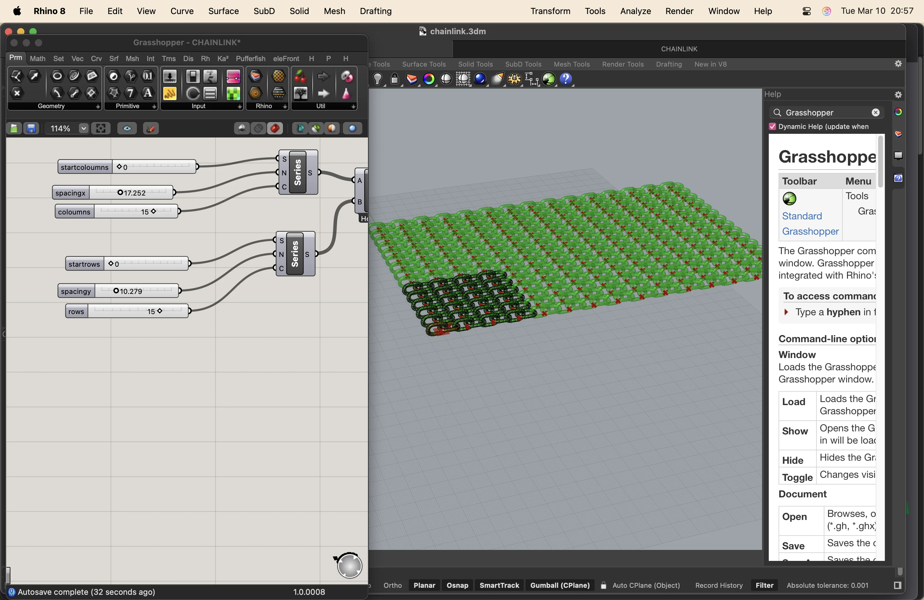
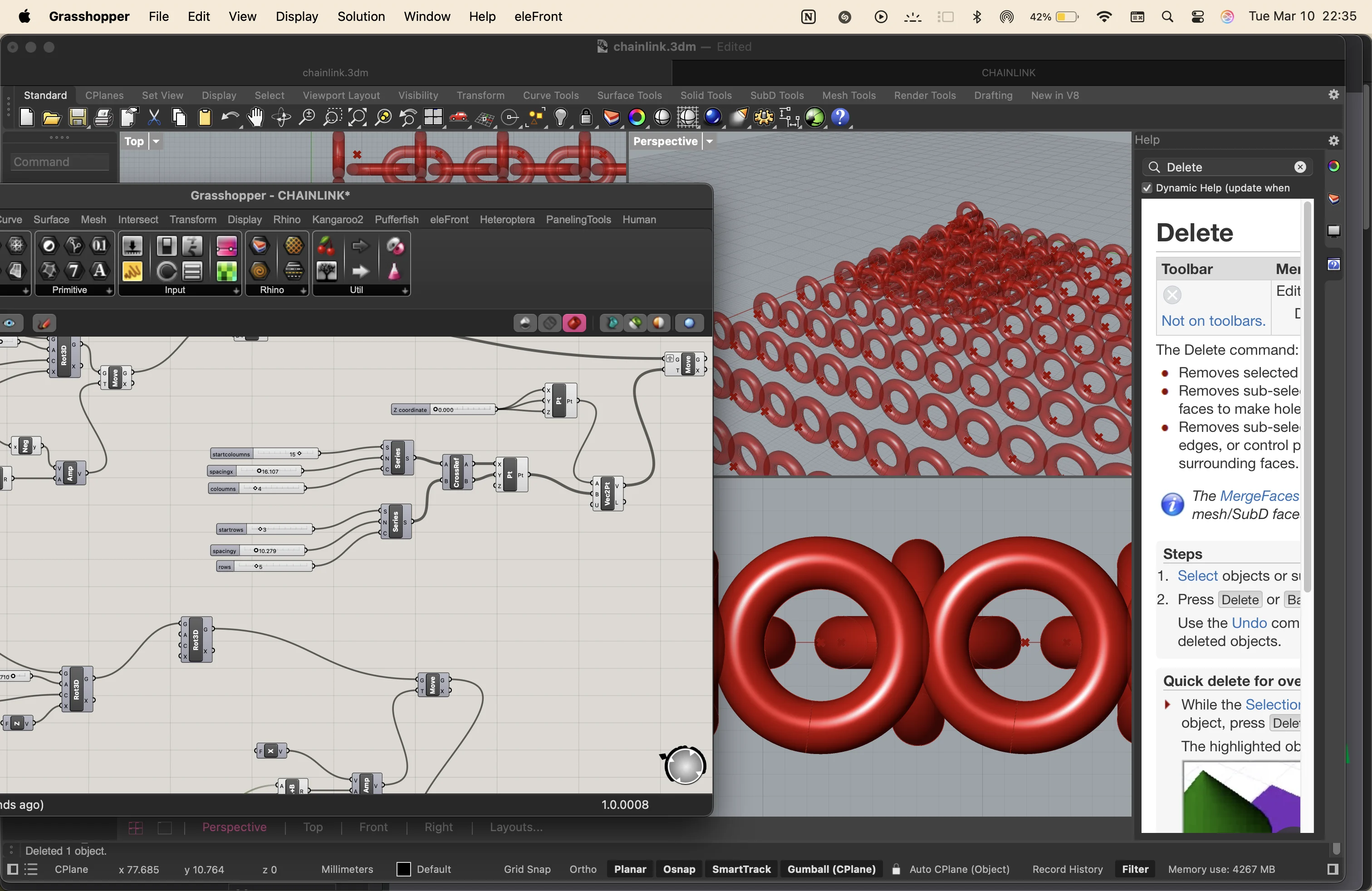
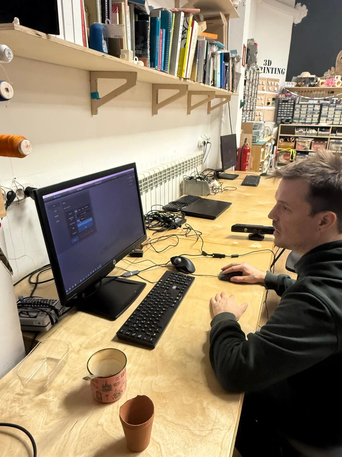
I started by adding a number of sliders to numerically control my dimensions and positions.
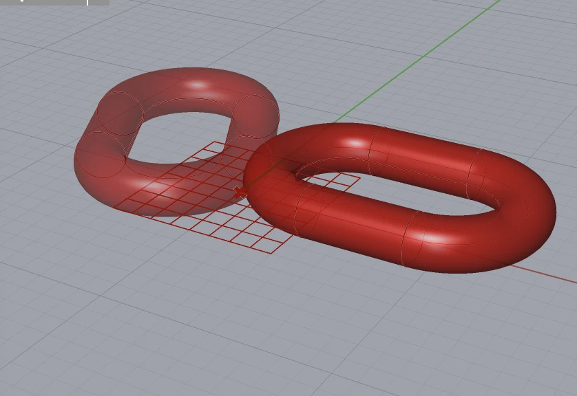
then I added a rectangle node and a pipe node to create the basic shape of the chainmail link.
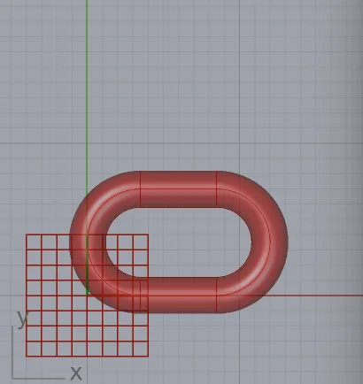
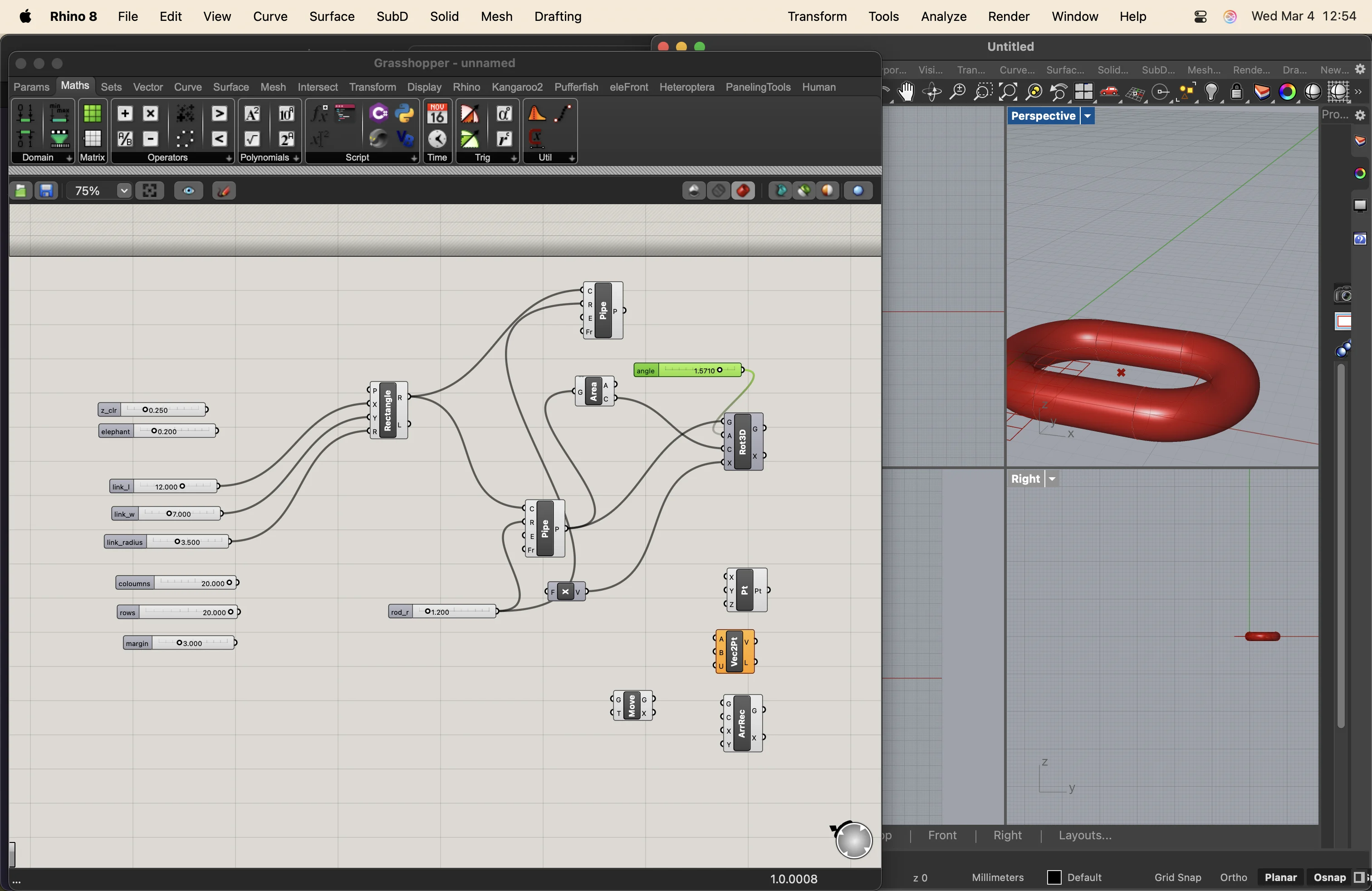
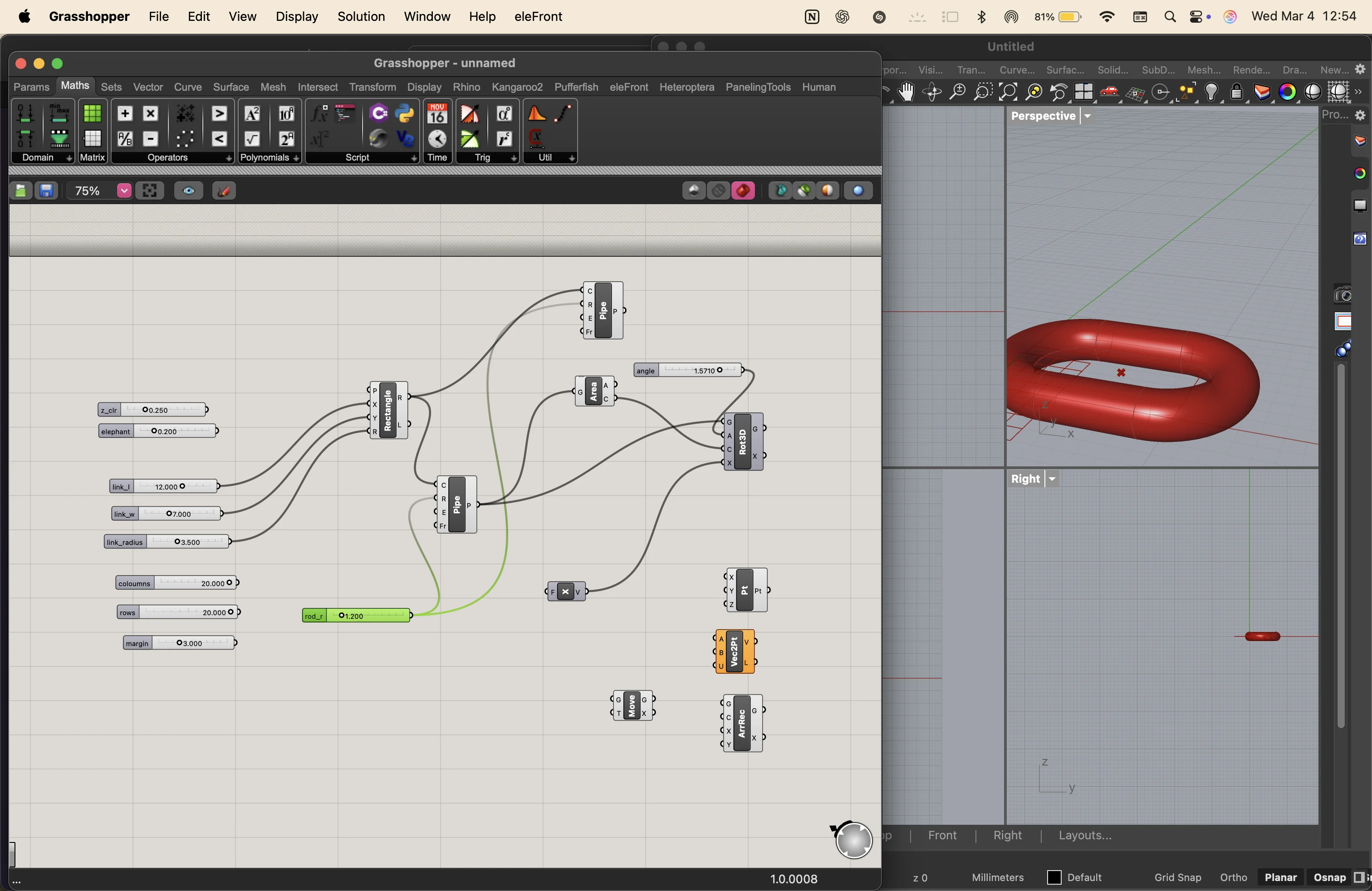
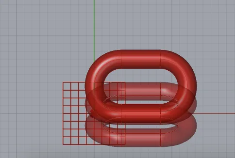
then I added series, move and rotate components to create 2 links attatched perpendicularly
adjusting and adding movement parameters in every axis and a negative direction to control the movement
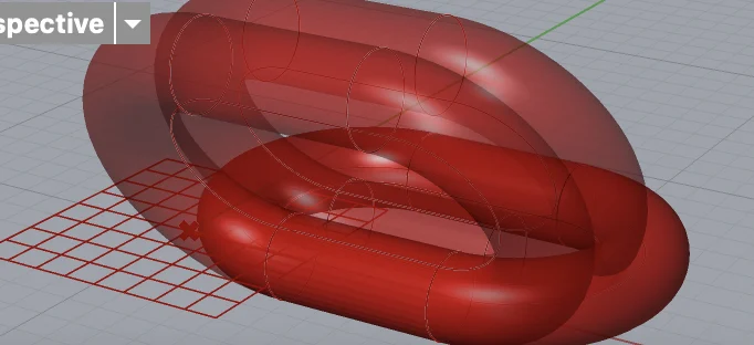
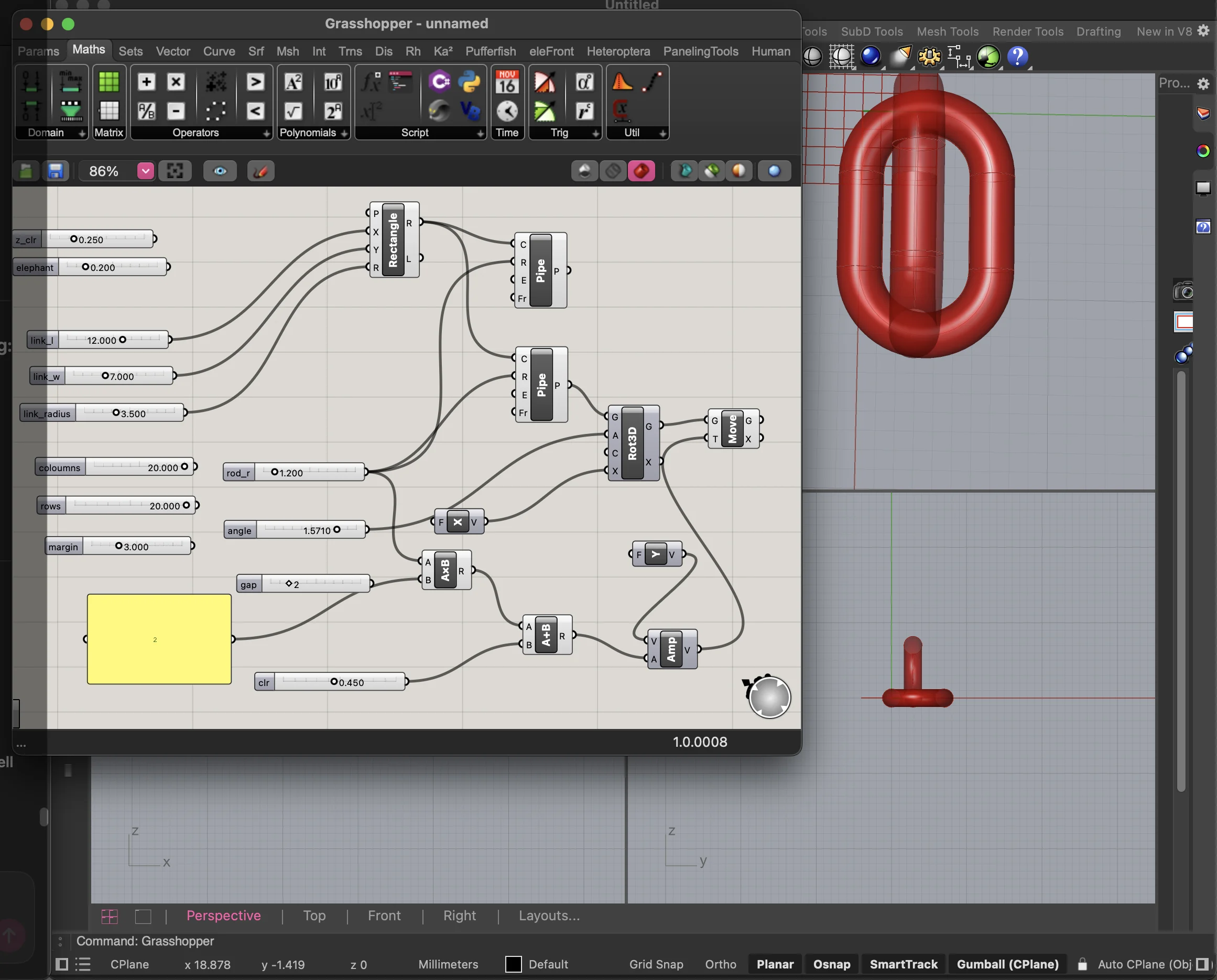
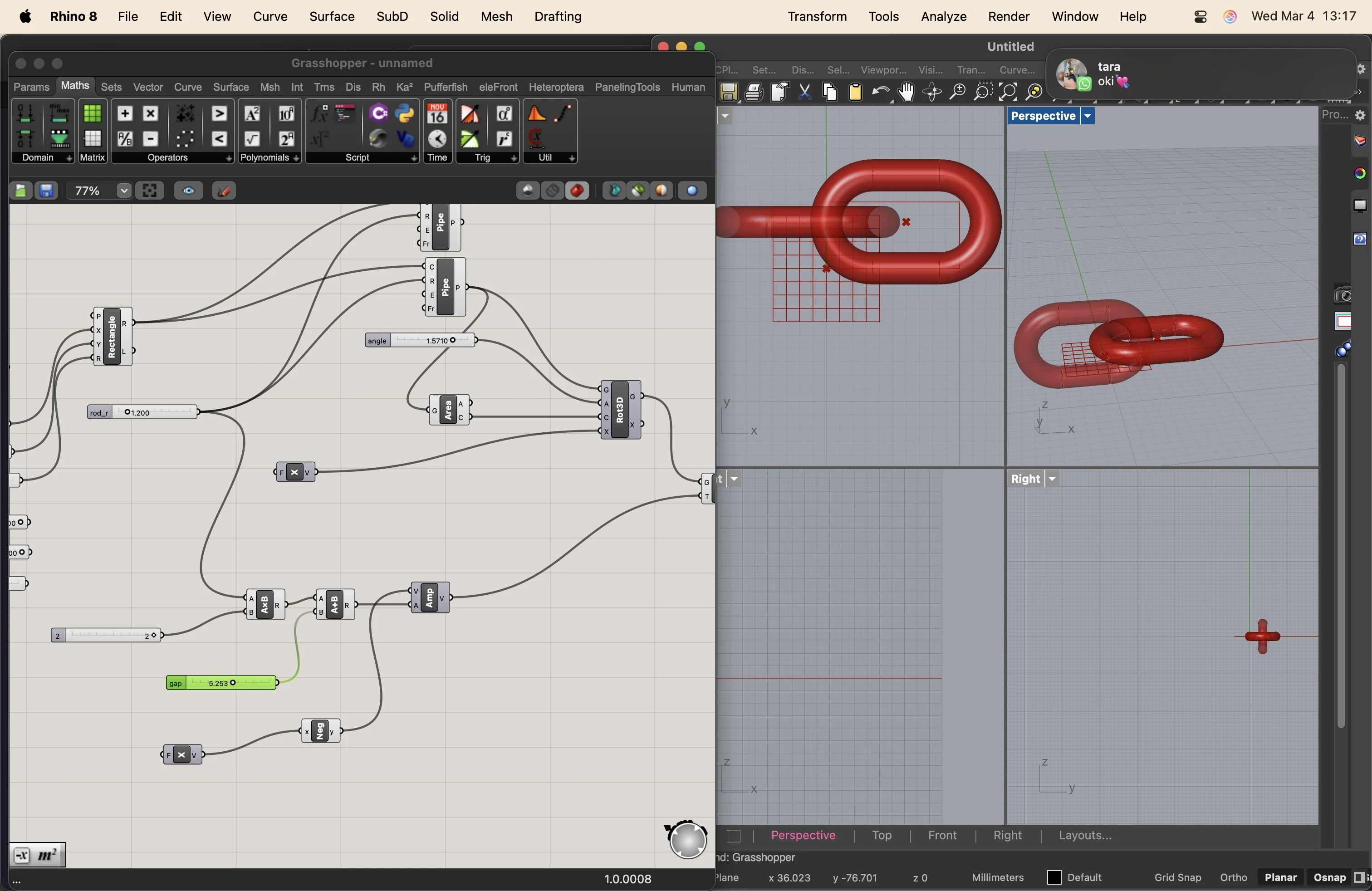
i had to toggle the view and disable the ones from the rot3d node
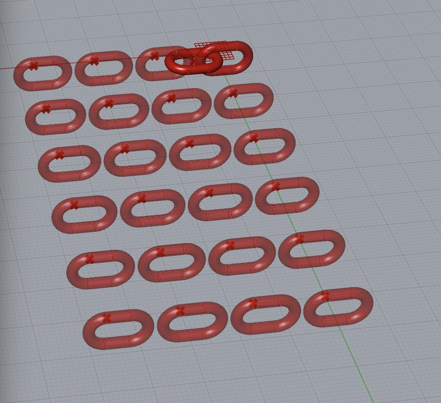
then i added an array to with number sliders to control the number of rows and coloumns before i baked the test print tile
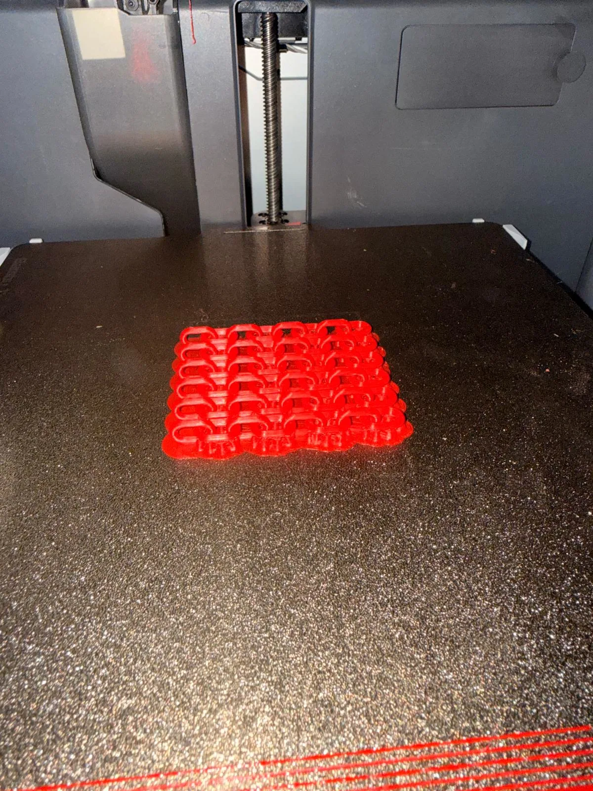
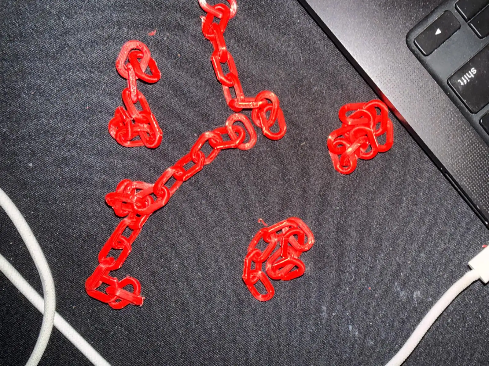
I made some small chains and 3d printed them
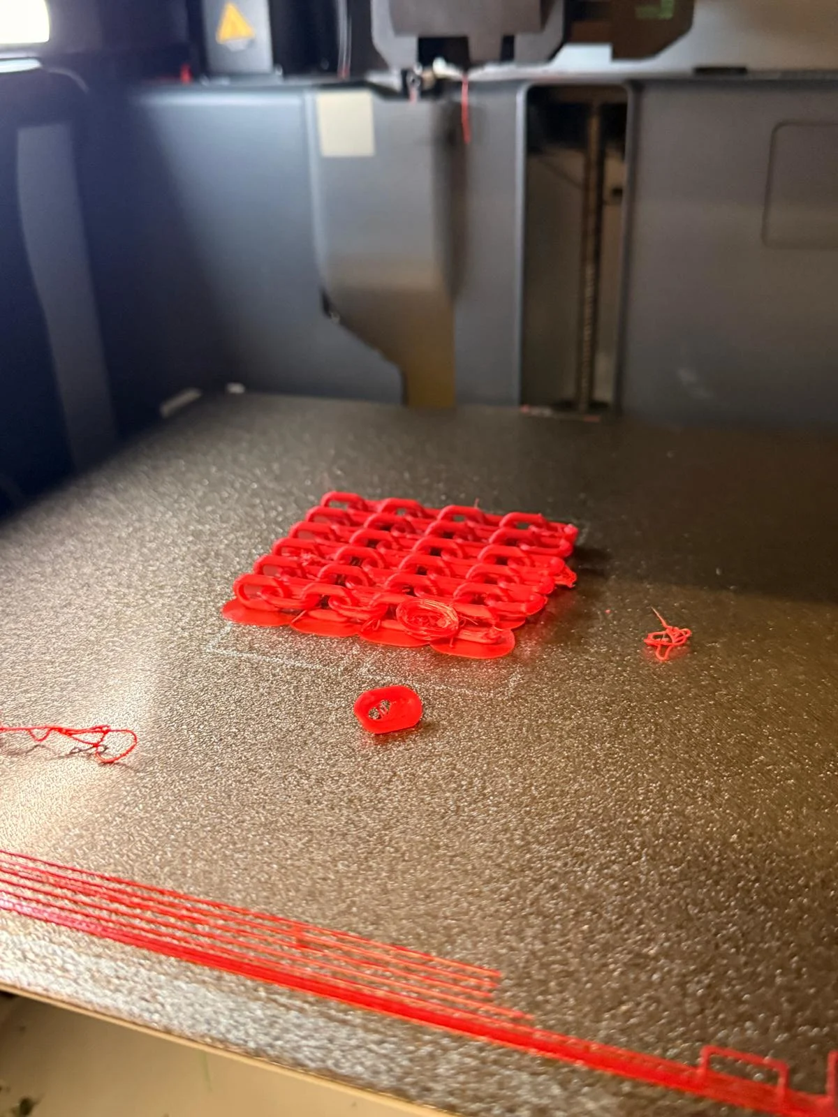
the first print was really wiry because i printed with just a brim
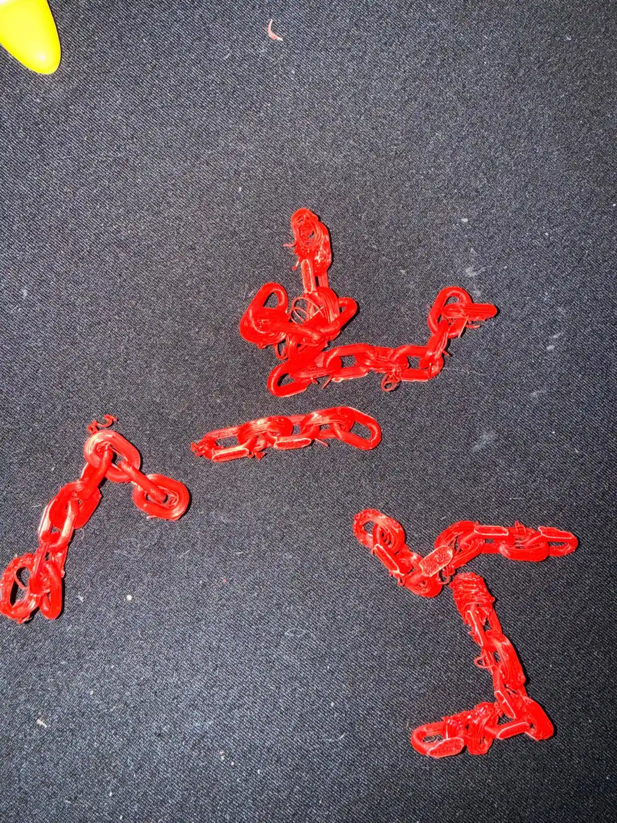
I retired the test print with supports, and it turned out really well.
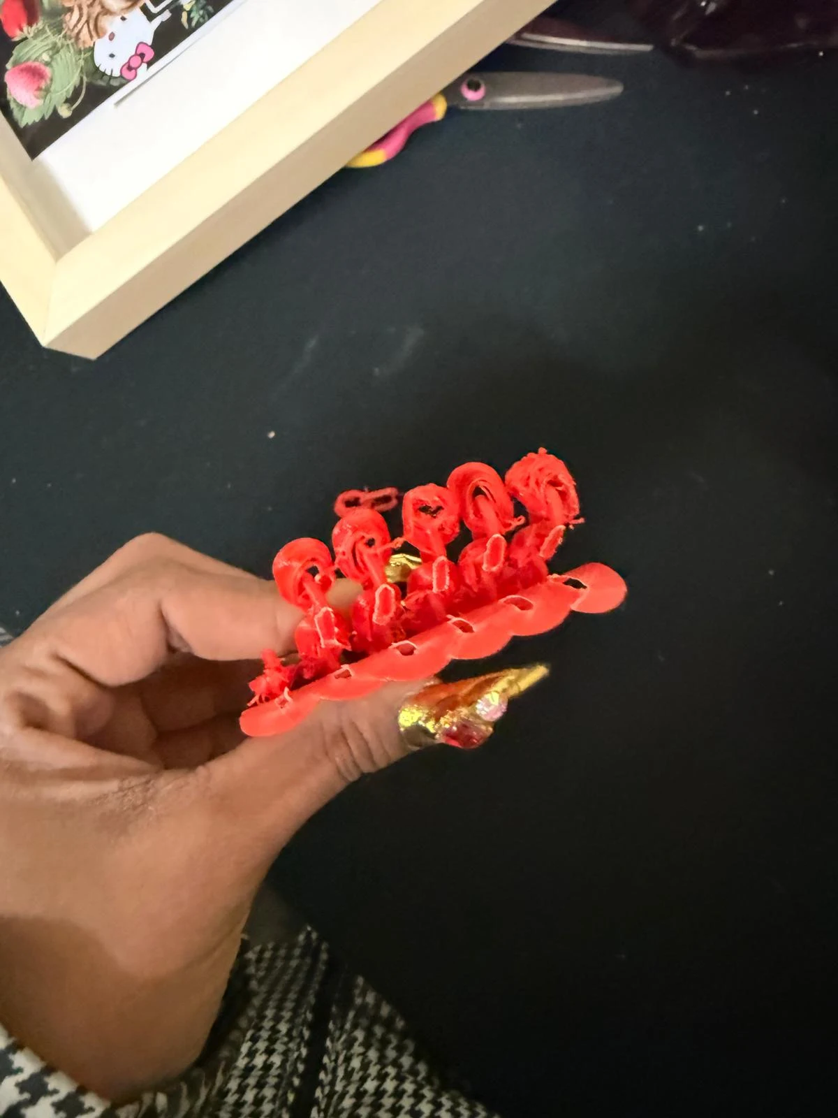
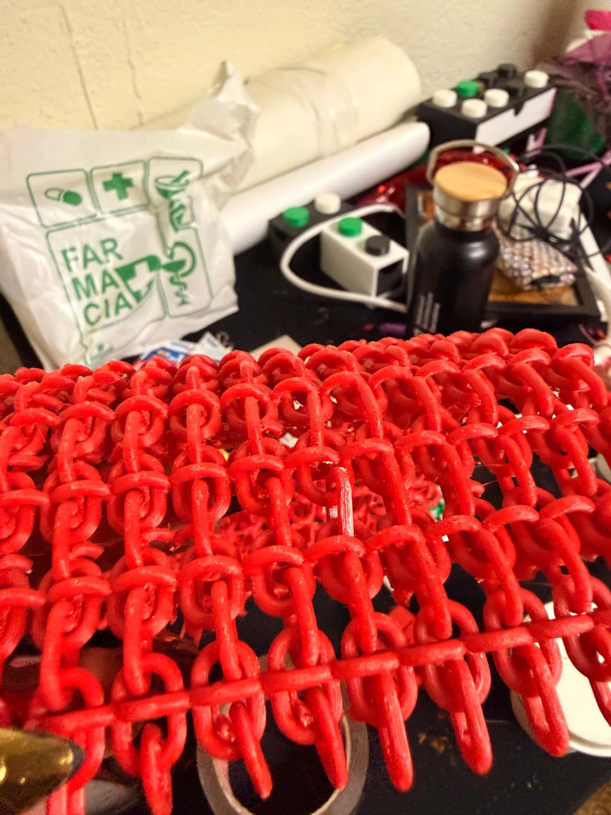
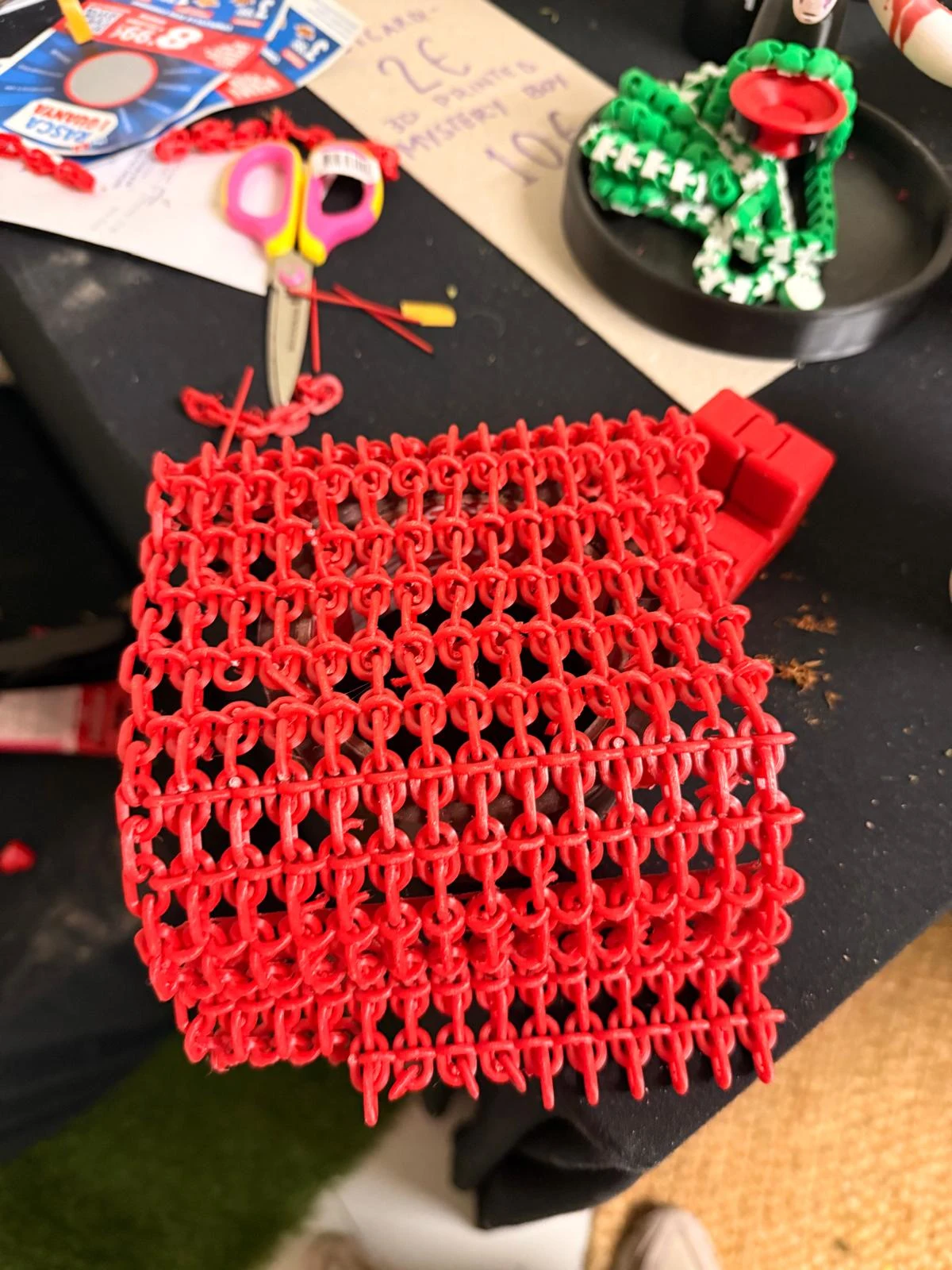
i copied the 2nd link and rotated it differently to create a textile like chainmail.
I printed this with suuports and it bends well in one direction.
I will have to reorient the 3rd link to achieve the desired flexibility. I will work on this and upload when successful!
here is the final textile I achieved so far
3d scanning
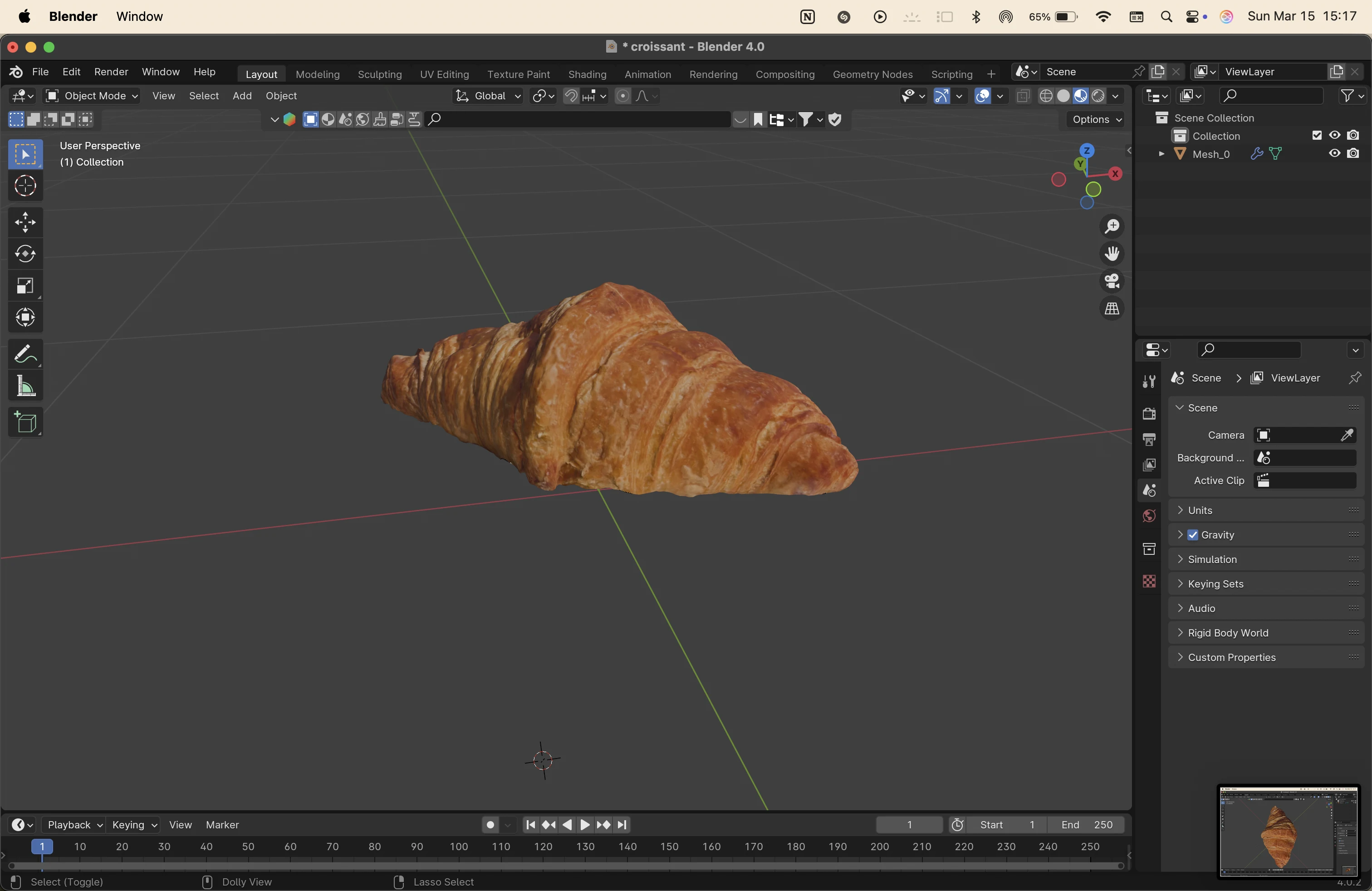
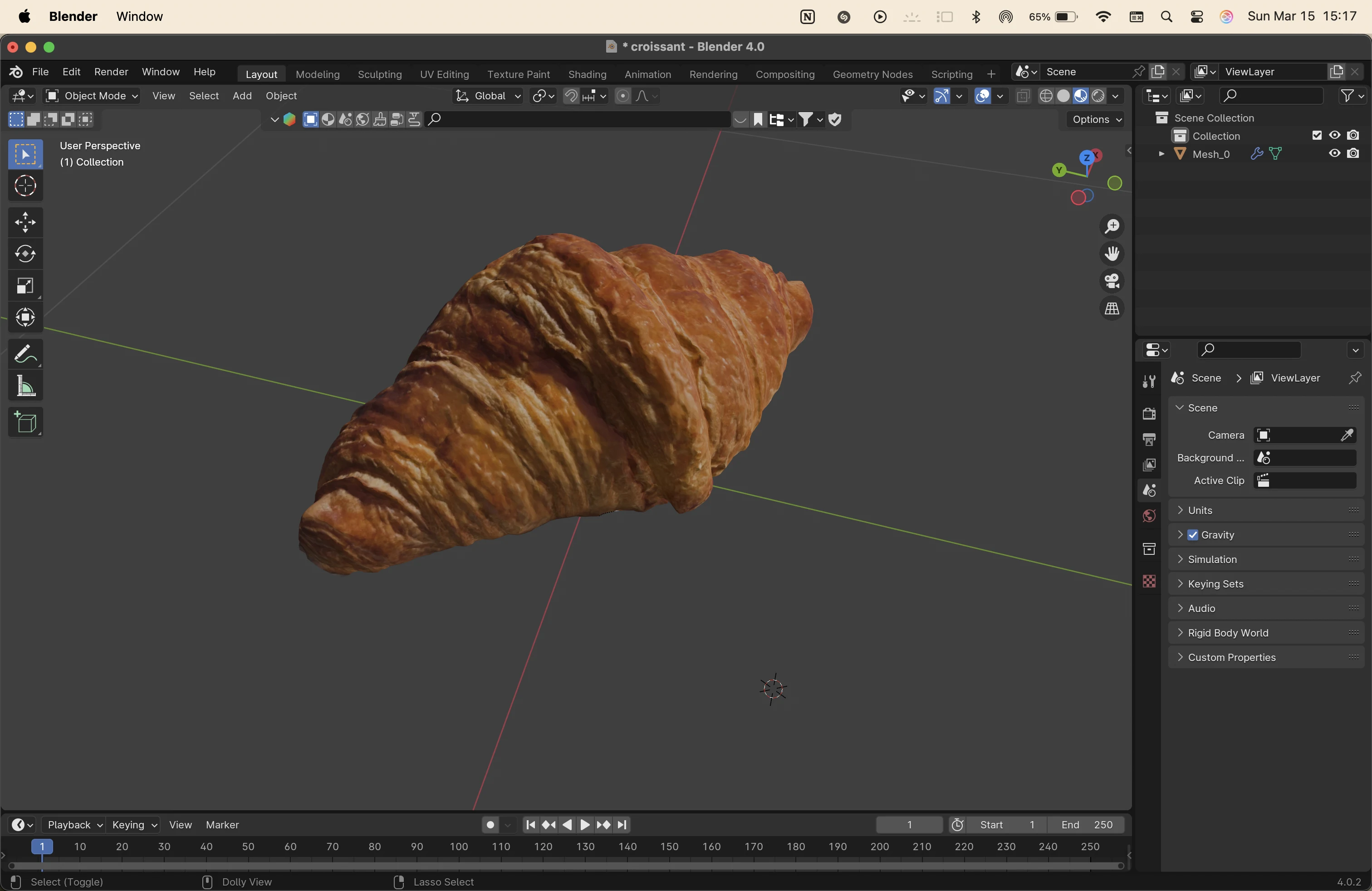
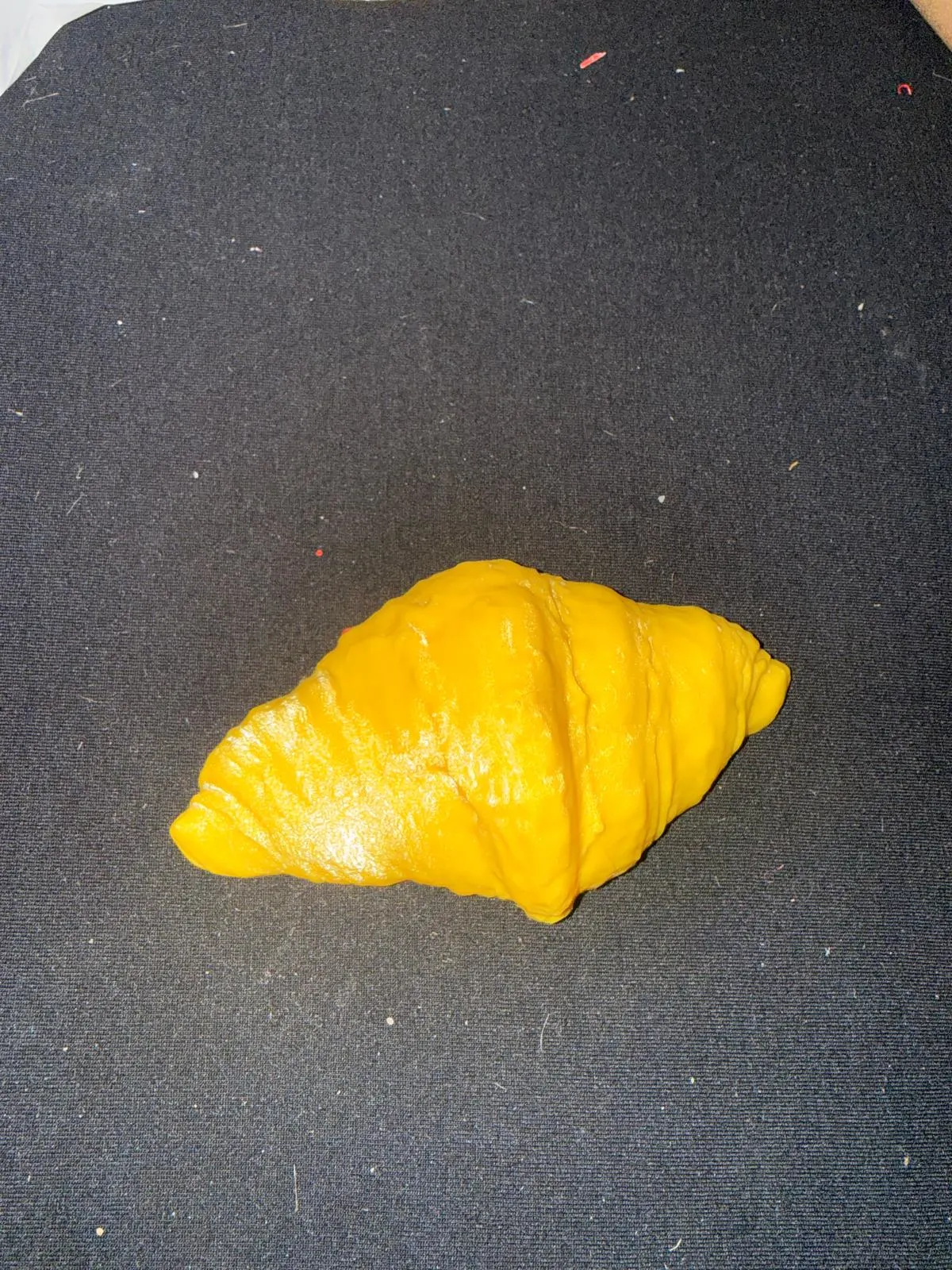
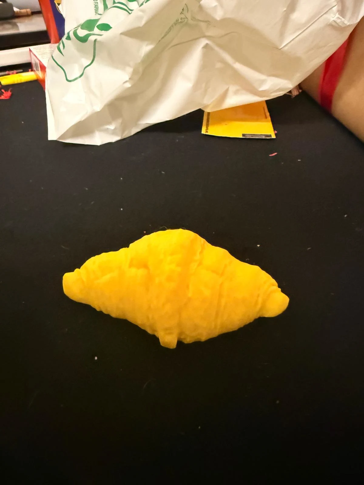
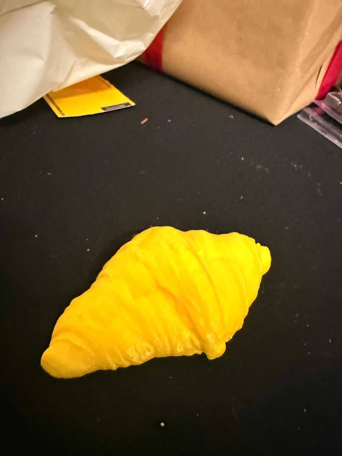
this week, i scanned a croissant.
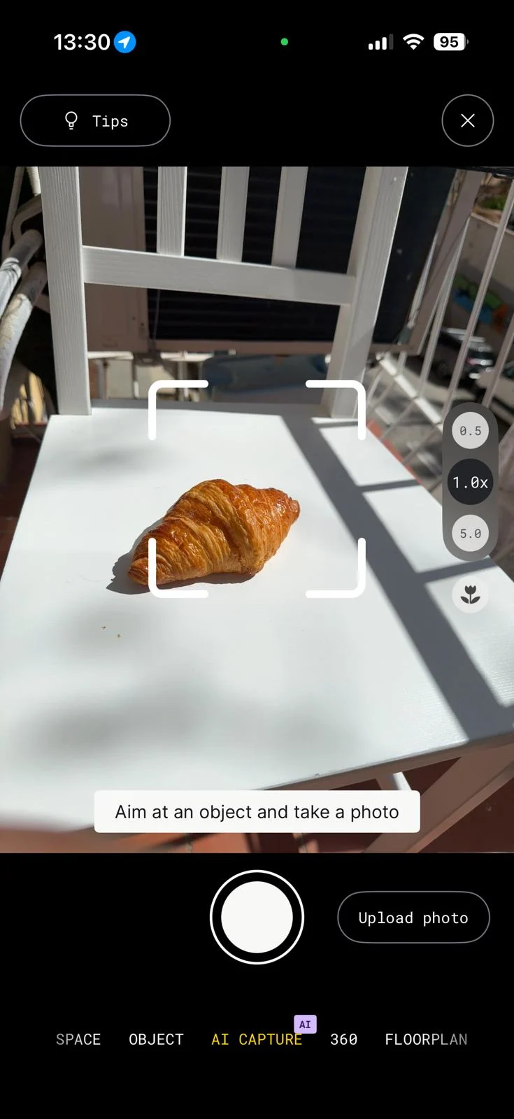
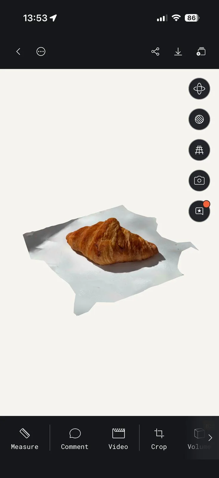
the croissant had a lot of texture and detail, which the scanner was able to capture well.
I used Polycam to scan and I could only download the gltf. of the file.
I cleaned up the model on blender and added a bottom surface to it on rhino.
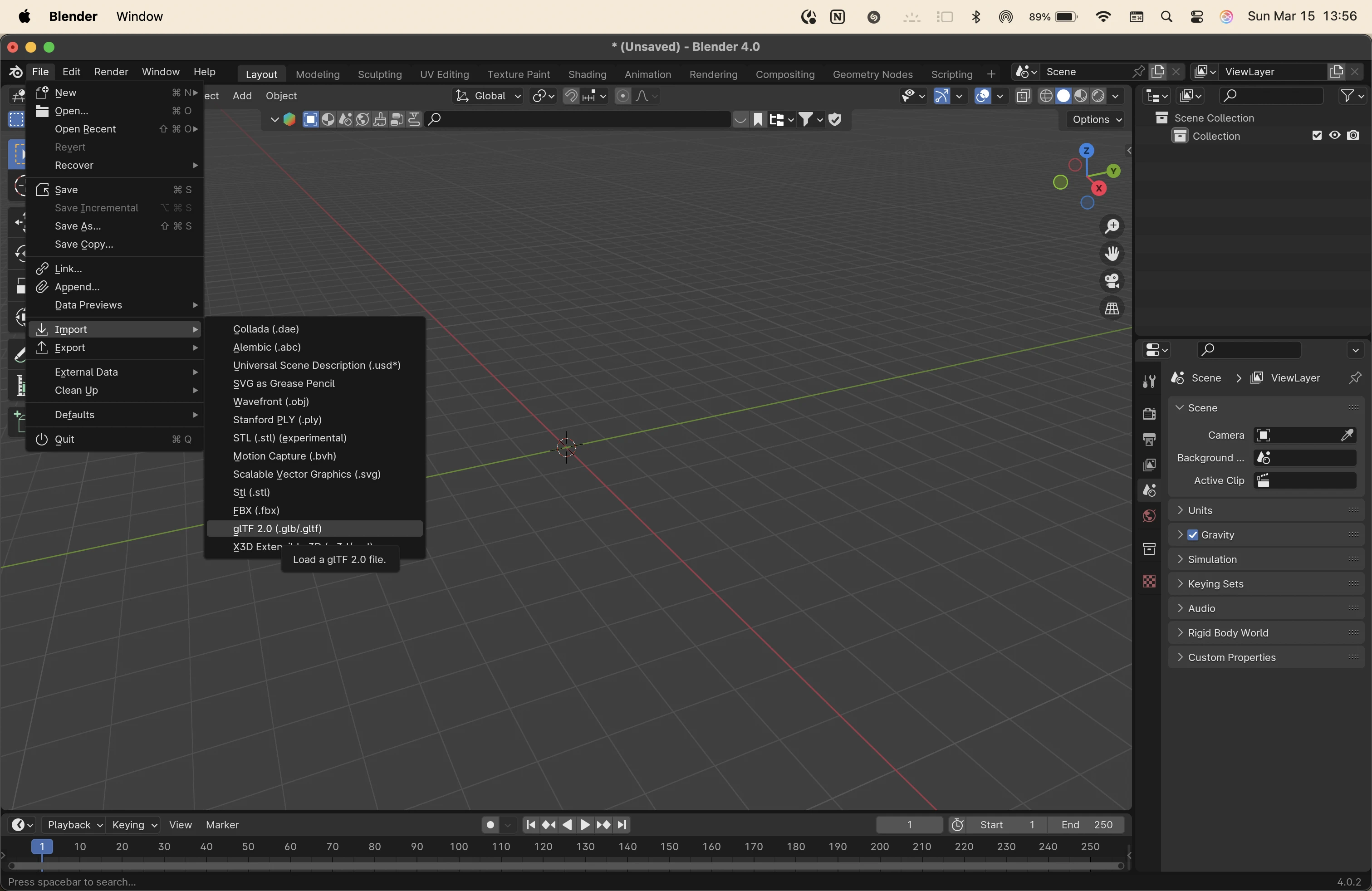
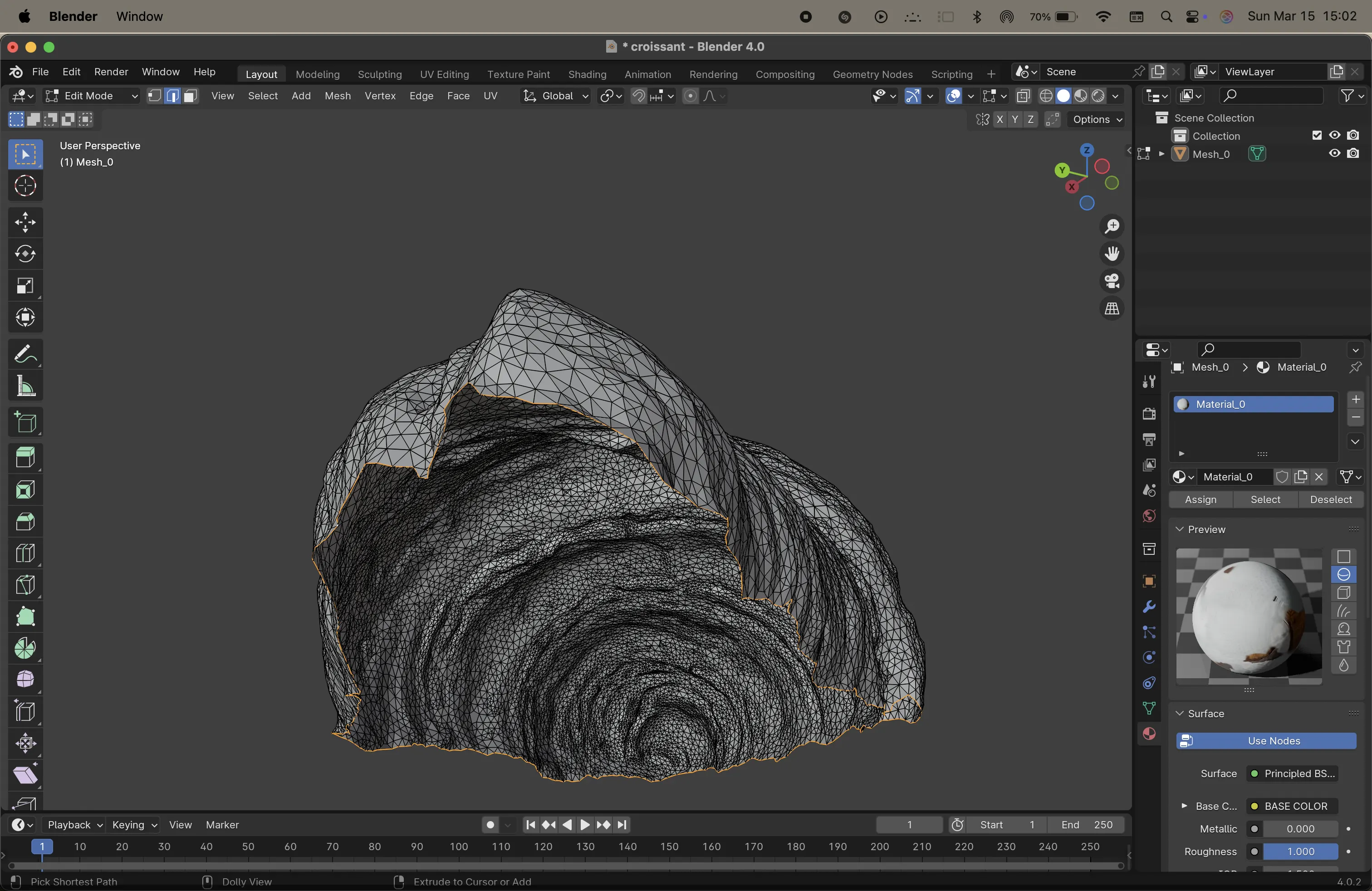
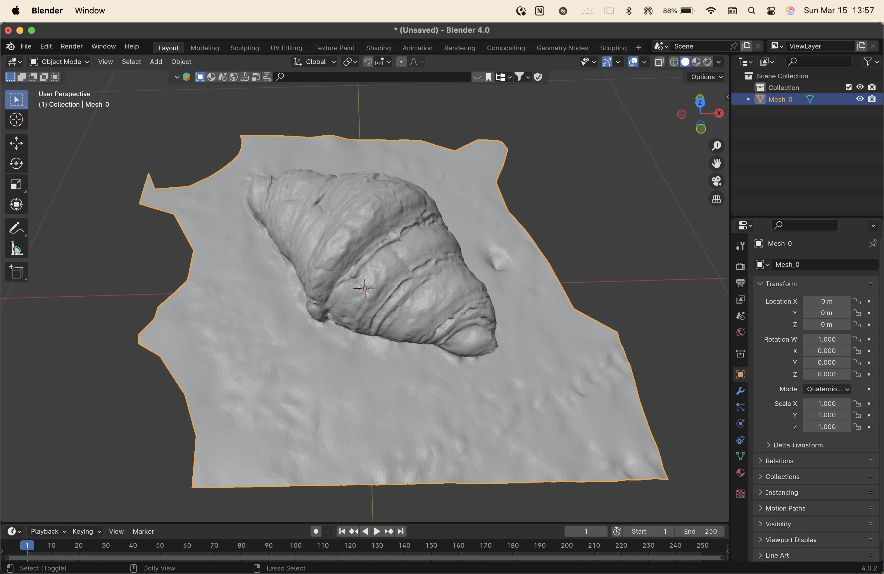
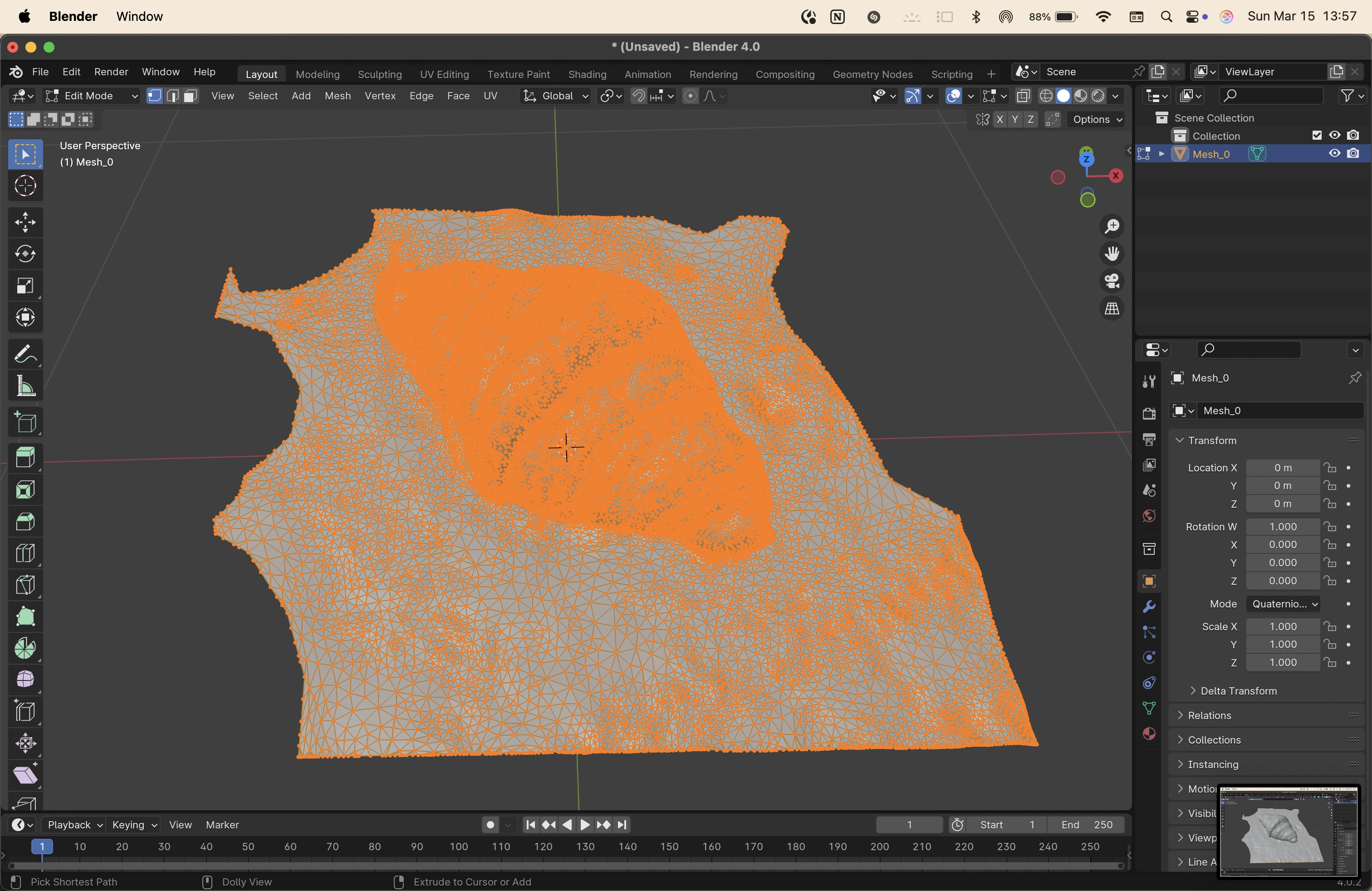
to clean up models on blender, I used went into the edit mode and removed the extra vertices, edges and faces.
then i used command+f to create faces from edges to fill up holes and smooth the outline of the base.
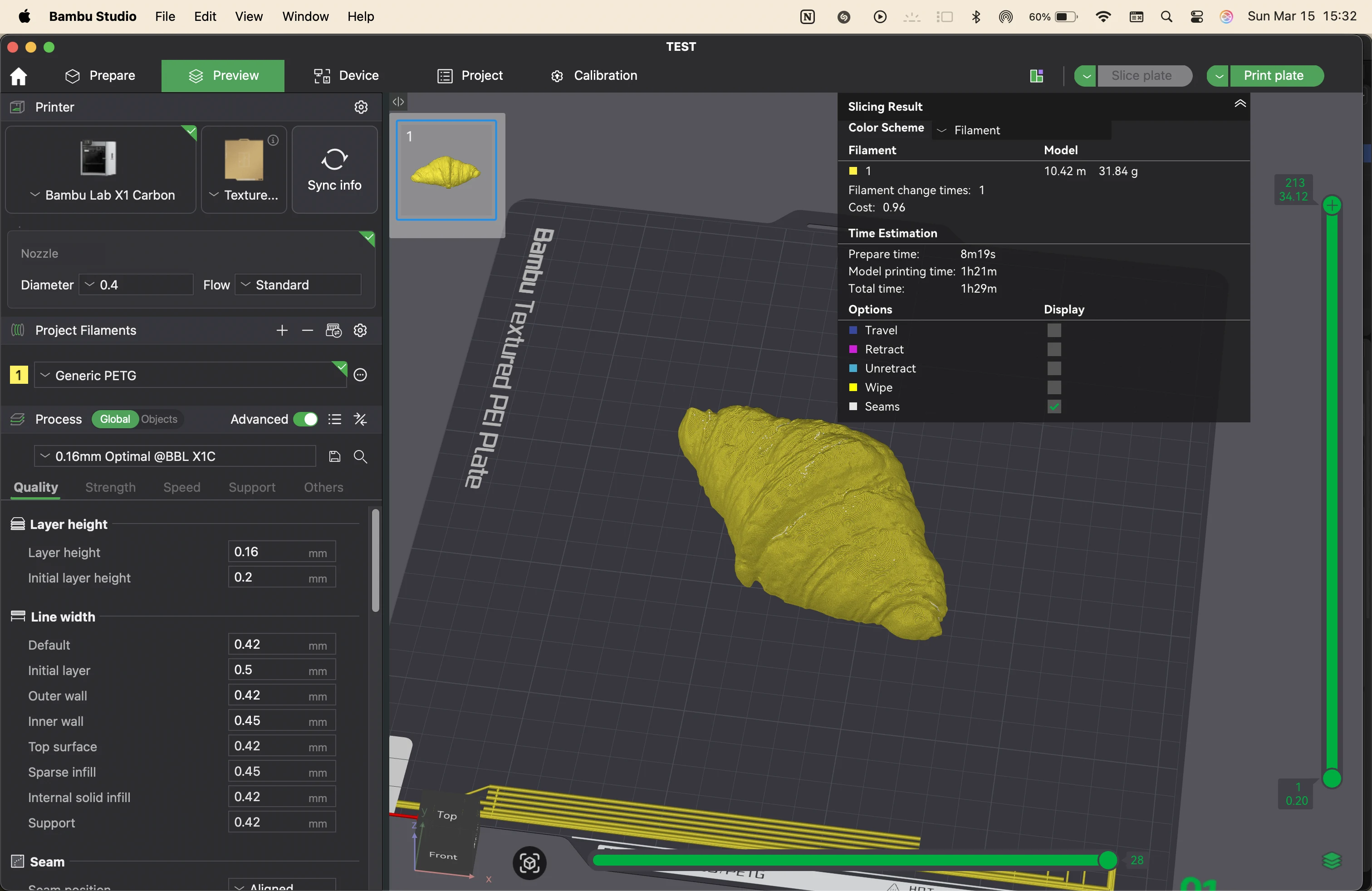
on rhino, I created a flat surface for the model to sit on, and did MeshSplit to make it a closed mesh.
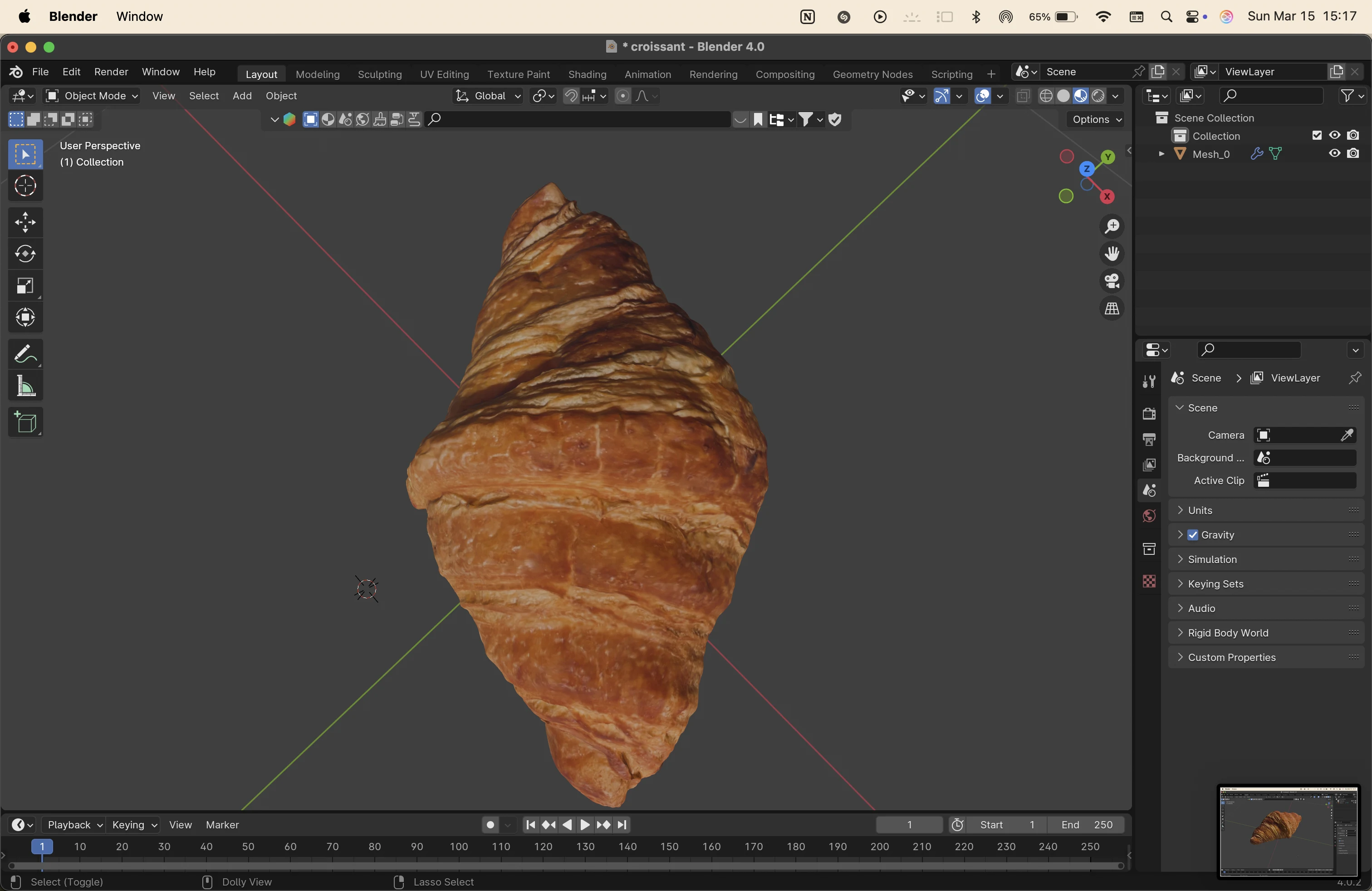
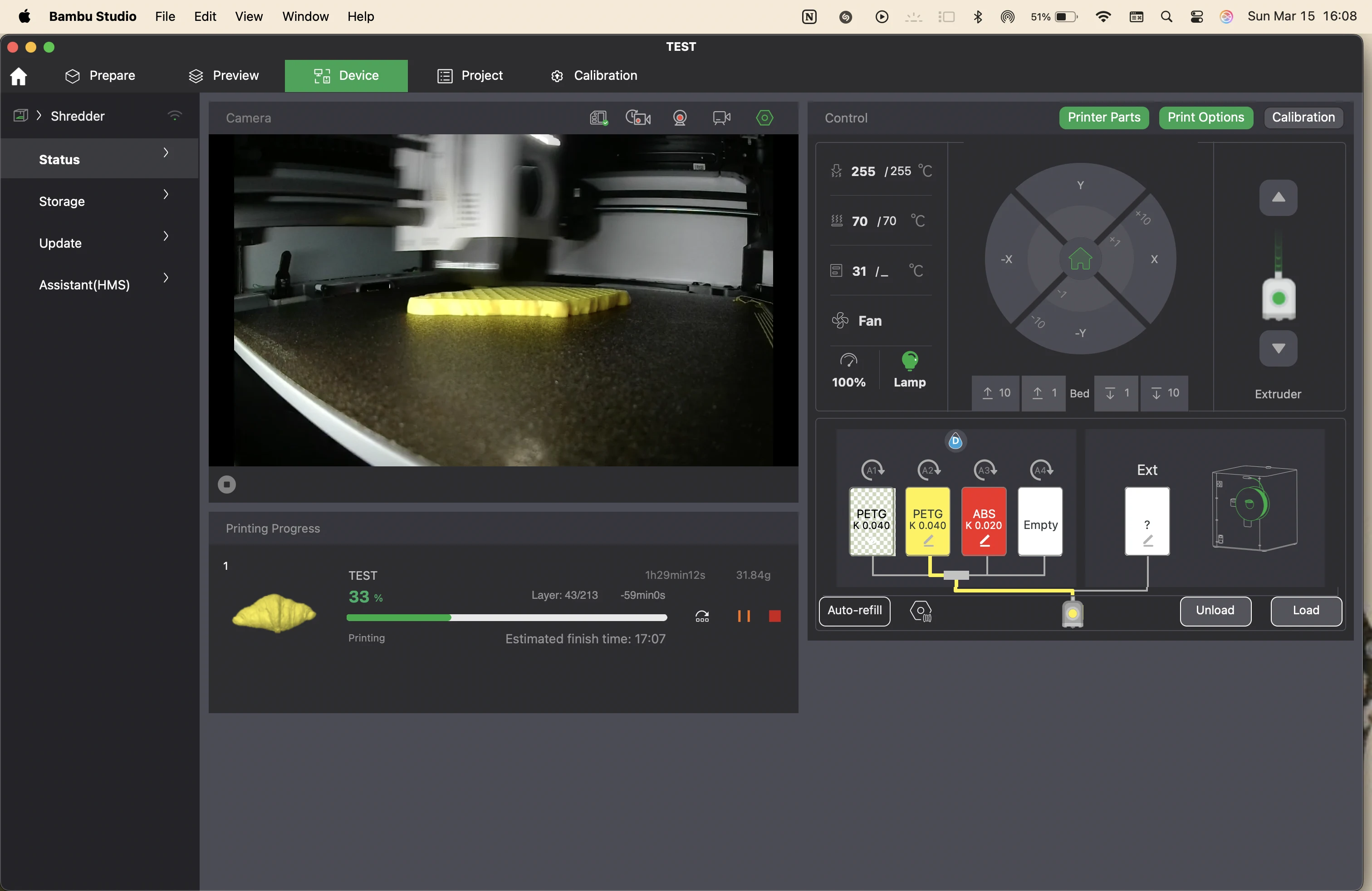
I printed the model with yellow PETG on the Bambu X1Carbon
original files
i had created the original files in rhino in grasshopper, which are all empty files now. please refer to the screenshots. but here are the 3mf files that i used to print the chainmail. and the scanning files
group assignment
here is the link to the group assignment page group assignment week 5
reflection
This week was a good recap of 3D printing & scanning. It is really important to understand materials used for printing & with reference to print settings to tackle issues like first layer adhesion, choosing the right extruder, temperature, etc.
We explored the possibilities & constraints of tool paths, saw some printers with various number of motors + axes.
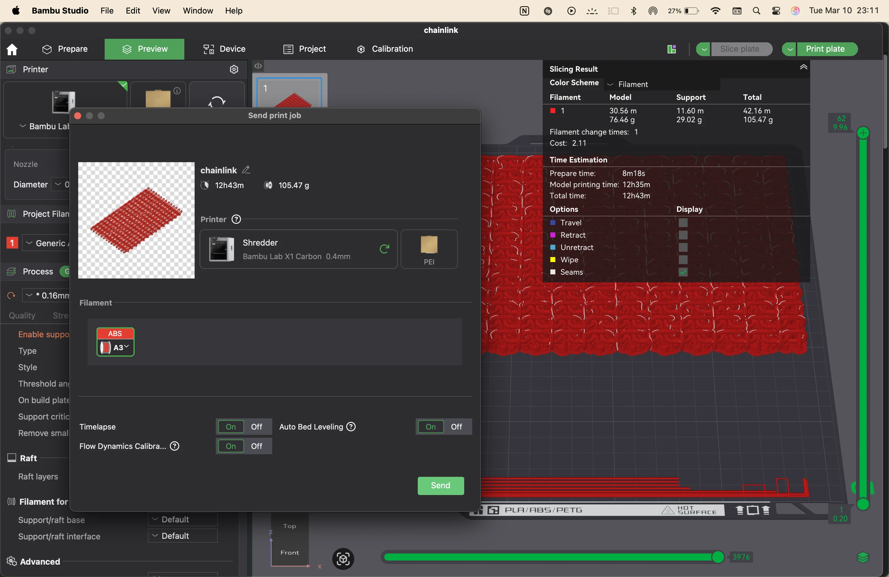
My contribution was to test & explore slicing settings & material usage, estimated print time & different settings. Bambu studio lets you preview the default presets of every material available in their library & to see the slice & preview of the printing process layer by layer. If you understand the G-code well, you can directly write the desired settings in the G code exported from Bambu studio.
The final sliced model estimated to 60.74g of filament & roughly 1 hour 15 mins of printing time including calibration & fabrication like bed-auto leveling, tool calibration & nozzle cleaning. It is important to balance & optimise print quality, time & material consumption. For example, the AMS colour changing feature is awesome! but it wastes a lot of material during colour filament change. It is possible to find a middle ground by designing the model in such a way that the colour change is minimal & playing with the orientation to reduce the number of changes.
It was also good to understand tool paths, seams, retractions and such details & how important they are to the finish of the final print. I’ve used an Ender Creality DIY printer & a Bambu X1C. The ender gives more control & customisation and is highly modifiable by someone that knows about printers. The Bambu on the other hand is much faster & cuts the printing time by almost a 10th compared to the Ender. But the firmware is not opensource for Bambu. The printers need to sent to certified repair centers.
Still I use the Bambu X1C way more just because of how fast & perfect it is. This lets me modify my ender to a clay extruder. I would love to figure that out.
notes
Week 5 – 3D Printing, 3D Scanning & Paste Printing
Class notes from the global lecture and local sessions.
Global Class Notes
The global class introduced the basic ideas behind 3D scanning and 3D printing. We discussed how scanned objects are digitally reconstructed and reviewed major additive manufacturing processes such as FDM, FFF, and SLA. We also revisited important concepts such as additive versus subtractive manufacturing, STL files, mesh geometry, slicing software, overhangs, supports, and print orientation.
the class notes were uploaded by me into chatGPT to create definitions and summaries of the concepts learned.
Introduction to 3D Scanning
3D scanning captures the shape of a real object and converts it into a digital model. The object is first recorded as many points in XYZ coordinates. These points form a point cloud, which is then converted into polygons and finally into a mesh. This mesh becomes the digital representation of the scanned object.
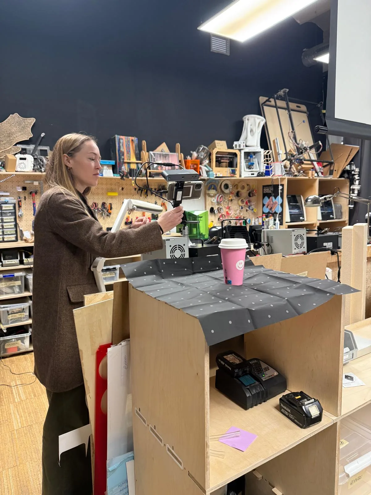
3d scanning my coffee cup and me
Binocular Vision and Triangulation
One scanning method uses binocular vision, which works similarly to human eyesight. Two points of view observe the same object, and triangulation is used to calculate the position of the object in space. This allows the scanner to identify depth and build up the geometry of the object.
3D Printing Overview
We learned that 3D printing has existed in some form for almost one hundred years. It belongs to additive manufacturing, where material is added layer by layer to build an object. This differs from subtractive manufacturing, where material is cut away from a larger block.
Types of 3D Printing
- FDM / FFF – Fused Deposition Modeling or Fused Filament Fabrication. This is the common filament-based process where melted plastic is deposited layer by layer.
- SLA – Stereolithography. This is a resin-based printing method where liquid resin is cured with light.
STL, Meshes, and Slicing
We reviewed how 3D models are prepared for printing. Models may begin as NURBS surfaces or as mesh geometry. If the model is made in NURBS, it is converted into a mesh and then exported as an STL file. The STL is then processed in slicing software, which generates the machine instructions needed for printing.
Overhangs, Supports, and Orientation
Overhangs are areas of a model that extend outward and may need support during printing. Supports are temporary structures added by the slicer to hold these parts in place. Orientation is also very important because it affects support usage, surface quality, print time, and part strength.
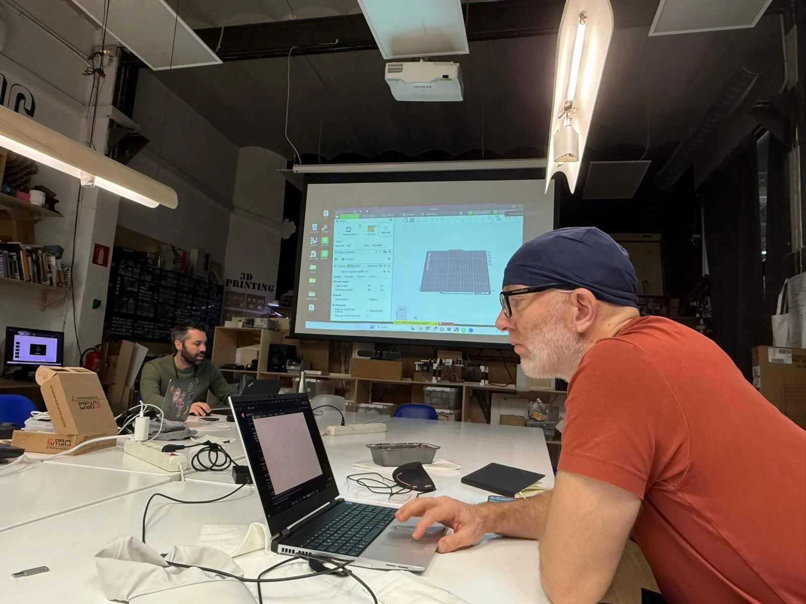
Local Class – FDM Printing with Shyam
The first local class focused on FDM printing and the parameters that affect print quality, print strength, and printing efficiency.
Infill
Infill controls the internal structure of the print. It changes the amount of material inside the object and affects both strength and print time. We learned that zigzag infill is usually used only for objects that are intended to bend.
Layer Height
Layer height affects both print quality and duration. Lower layer height gives higher quality and finer detail, but it also increases print time. Higher layer height makes the print faster but reduces surface detail.
Supports
Supports help hold up parts of the model that would otherwise collapse during printing. Their need depends on the geometry and the orientation of the object.
Part Strength
FDM prints are stronger along the layers and weaker across them. In other words, parts are generally stronger parallel to the print layers and weaker perpendicularly because the layer bonding is more fragile than the material inside a single layer.
Ribs and Fillets
We learned that ribs and fillets can strengthen a model. Ribs increase stiffness, and fillets help reduce stress concentration around edges and corners, which can improve the structural performance of the printed part.
Materials
- PLA – easy to print and commonly used for prototypes.
- ABS – stronger and more heat resistant, but more difficult to print.
- PETG – durable and useful when more strength or flexibility is needed.
- TPU – very flexible and suitable for soft parts.
- HIPS – useful as a support material and can be dissolved in the appropriate solvent.
Generative Design and Modeling Workflow
Fusion was mentioned as a software used for generative design, although for this class I used Grasshopper instead. The general workflow is that the model is created either as NURBS or as mesh geometry, and if it starts as NURBS it must be converted into a mesh before export as STL.
Non-Manifold Geometry
We learned that non-manifold edges can create errors in 3D models. This often happens when objects overlap without being properly joined with a Boolean union. Problems like overlapping faces or broken geometry can cause slicing issues and failed prints.
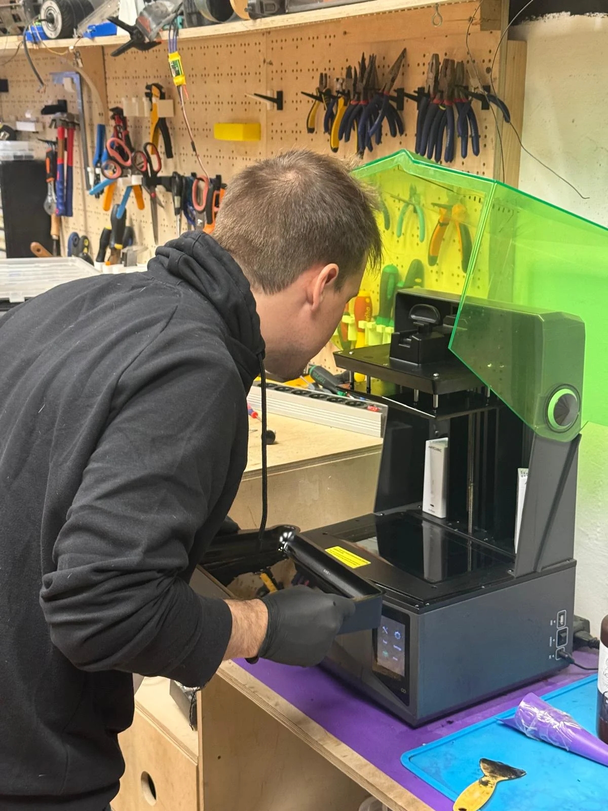
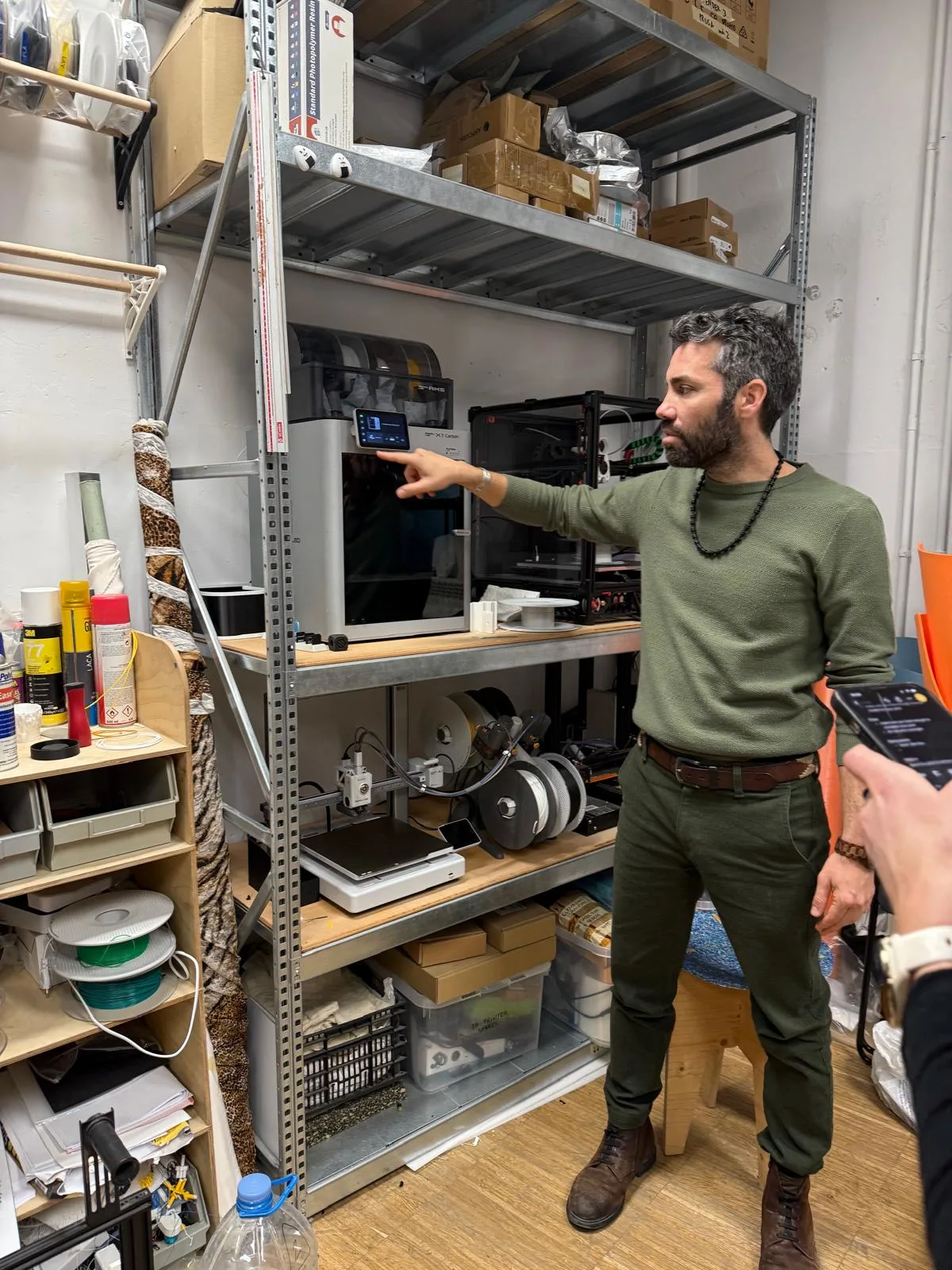
Local Class – SLA Printing with Dani
The afternoon local class focused on SLA resin printing, its workflow, advantages, and preparation requirements.
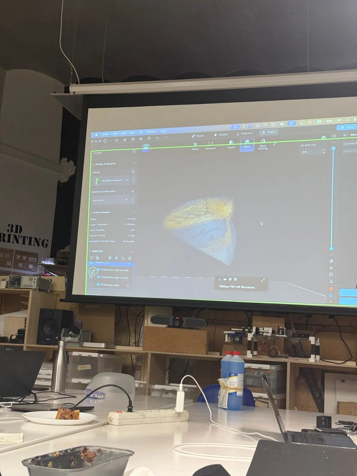
Benefits of SLA Printing
SLA printing can produce highly detailed parts with smooth surfaces. One important advantage is that print time is mostly related to the height of the print and number of layers rather than the number of objects placed on the build plate. This means several objects of similar height can often be printed in the same amount of time as a single object.
Printer and Software
We learned about the Saturn 4 resin printer and the use of ChituBox to prepare SLA files. ChituBox is used to orient models, generate supports, and set slicing parameters before printing.
SLA Design Considerations
- If a model has closed cavities, holes need to be added so that liquid resin can escape.
- The orientation should usually be oblique, diagonal, or sideways to reduce suction and vacuum effects.
- Bottom exposure time must be adjusted depending on the material being used.
Cleaning and Preparation
We learned that isopropyl alcohol must be used to clean the machine and printed parts. It is important to clean the build plate, the tray bottom, and other relevant surfaces before starting a print and during post-processing.
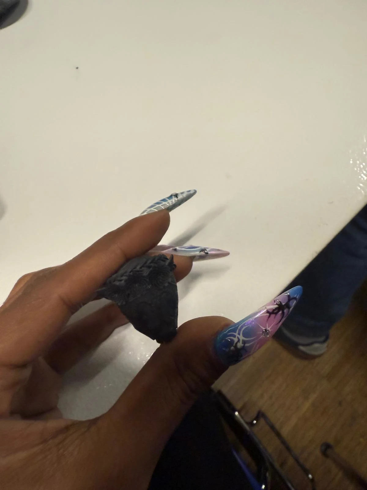
Post-Processing and Electroplating
Another interesting point from the session was that resin prints can be electroplated after printing, which opens up possibilities for different finishes and material effects.
Multicolor Printing and Material Waste
We also discussed that multi-color printing creates a lot of material waste because the printer has to purge filament during color changes. To reduce waste, it may be better to orient the model differently or print it in separate parts.
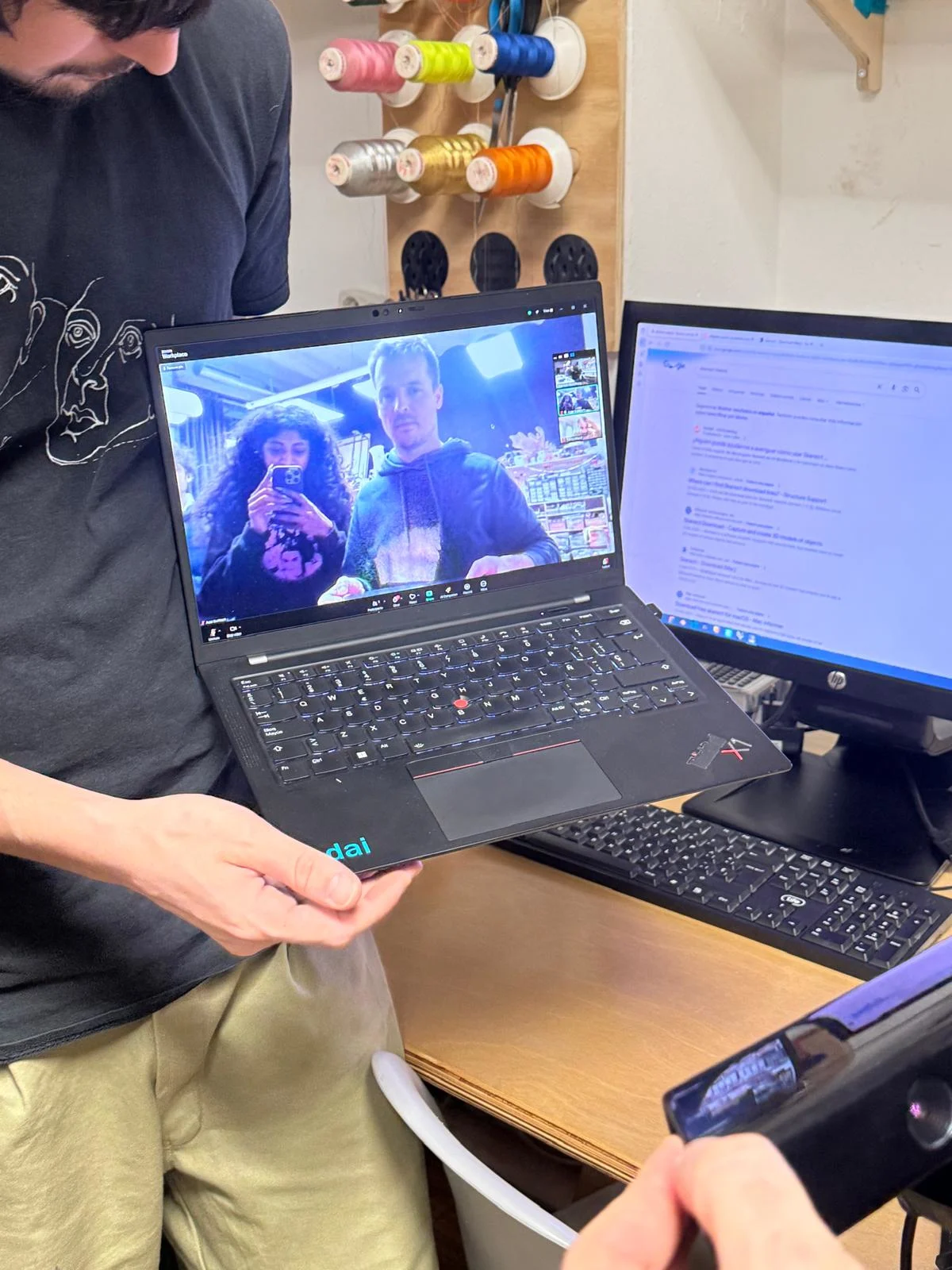
Local Class – 3D Scanning with Adai
The local 3D scanning session introduced LiDAR scanning, point clouds, and photogrammetry workflows.
LiDAR and Point Clouds
LiDAR scanning records a large number of points around an object, often forming a dome-like field of information. These points make up a point cloud, which is later processed into a mesh by joining edges and forming surfaces.
Photogrammetry
Photogrammetry is the process of creating a 3D model from many photographs. By comparing overlapping images of the same object, the software reconstructs shape and depth and generates a point cloud and mesh.
AliceVision
AliceVision was mentioned as an open-source 3D scanning and photogrammetry software that was considered very good, especially at one point in time.
Good Practices for 3D Scanning
- Take many photos from many angles.
- Keep the lighting as consistent as possible throughout the scan.
- Transparent objects are difficult to scan.
- To scan transparent objects, it may help to spray them with dust or with a disappearing scanning spray.
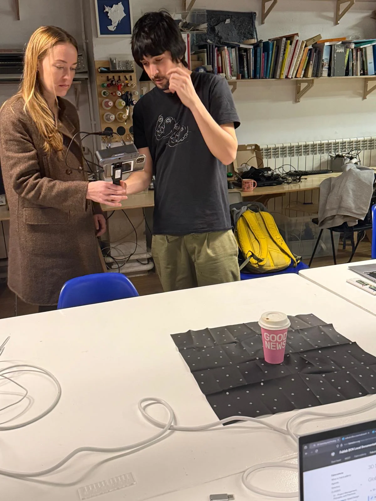
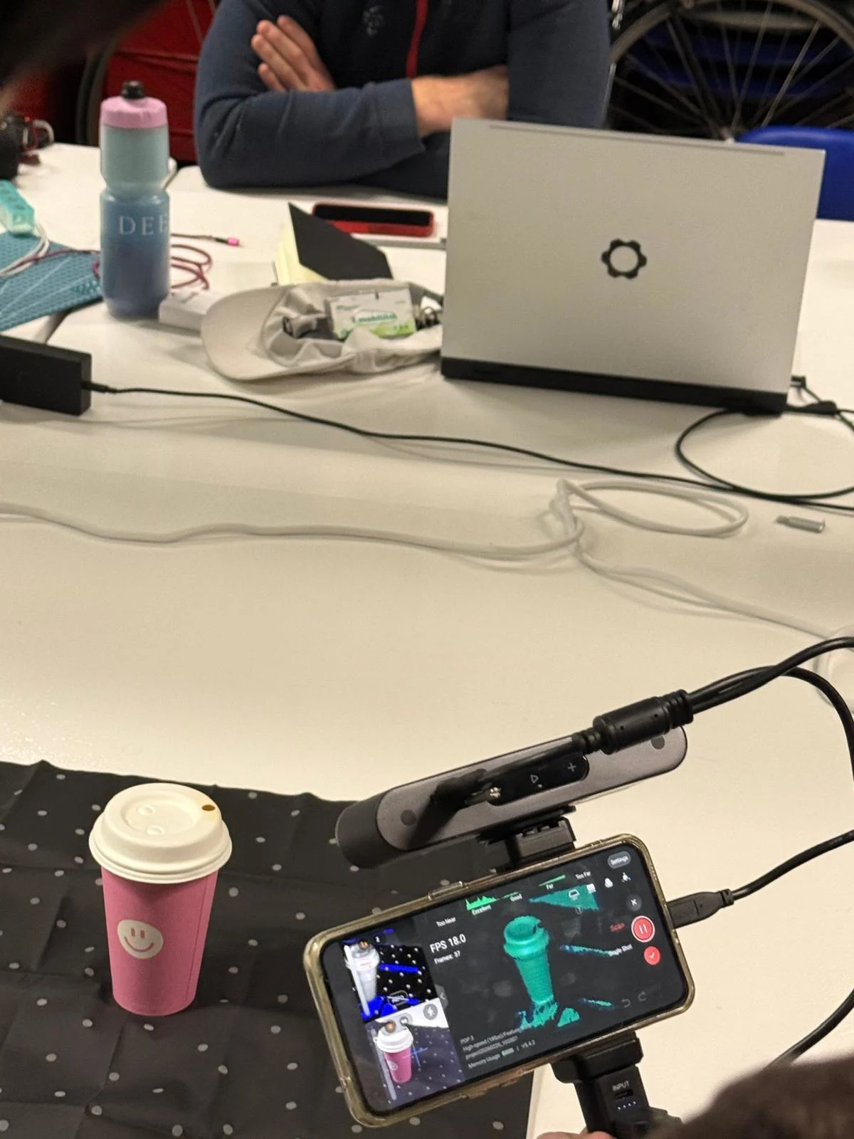
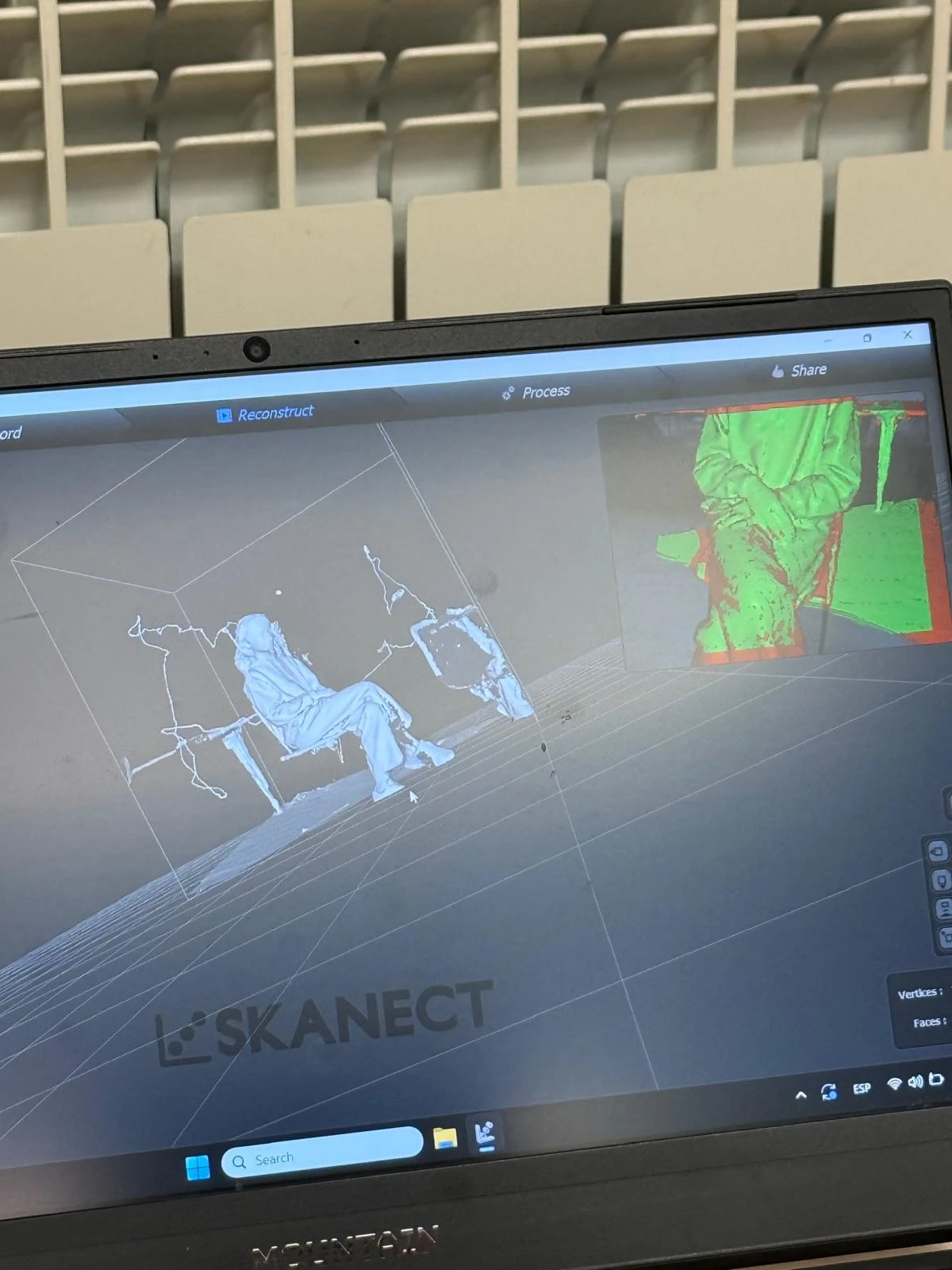
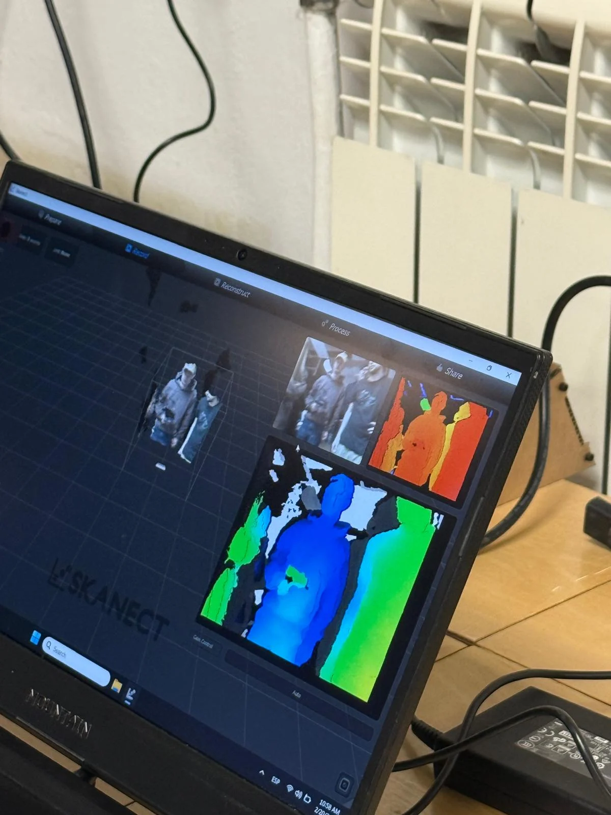
for the demonstration, we 3d scanned my coffee cup.
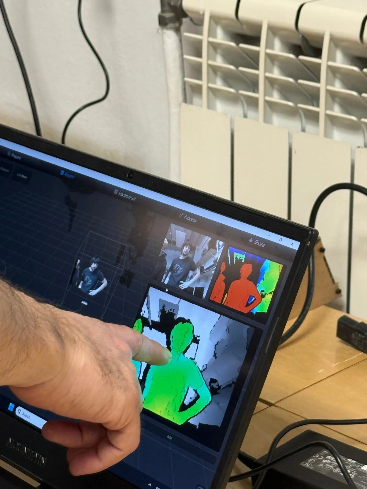
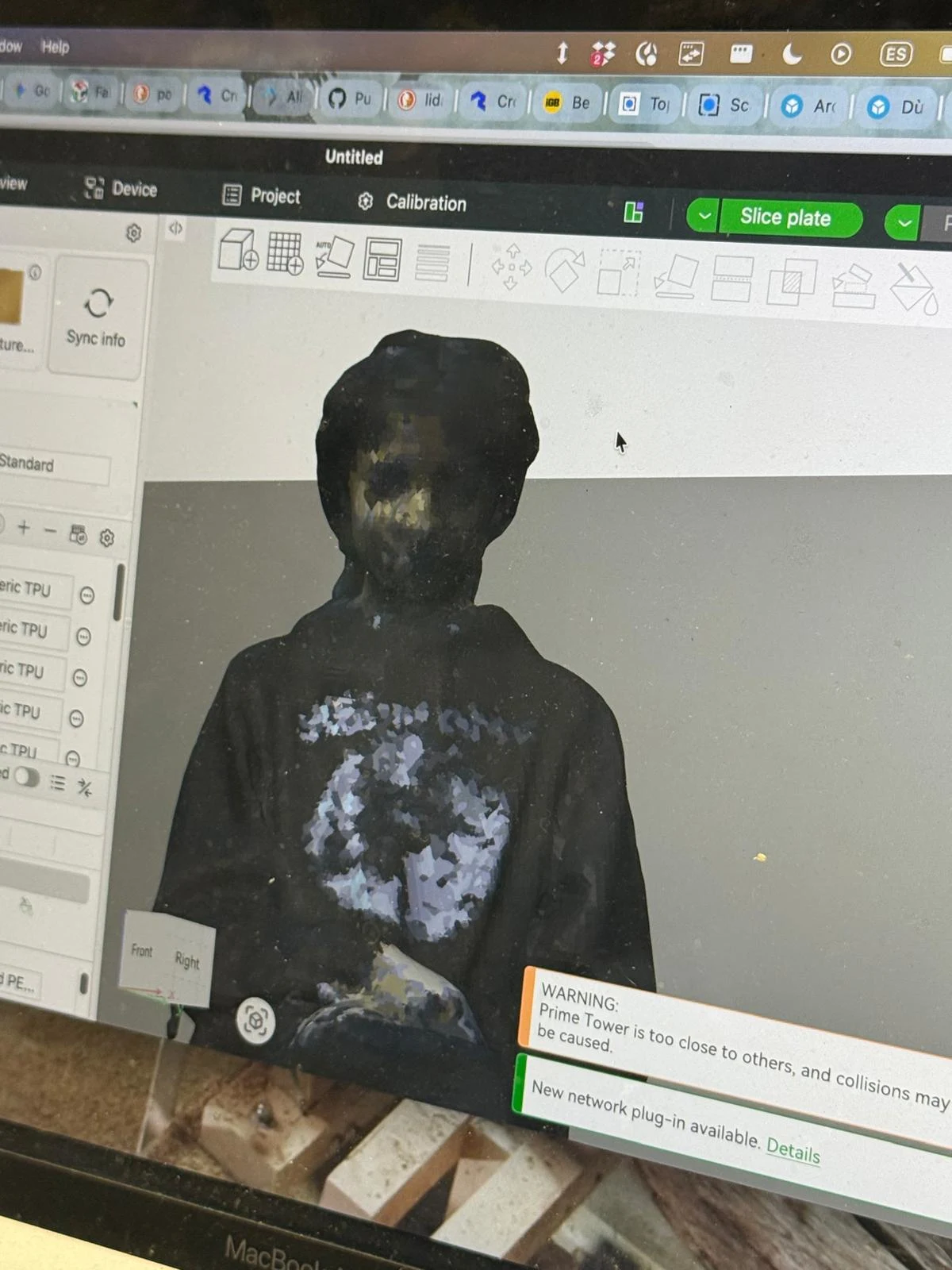
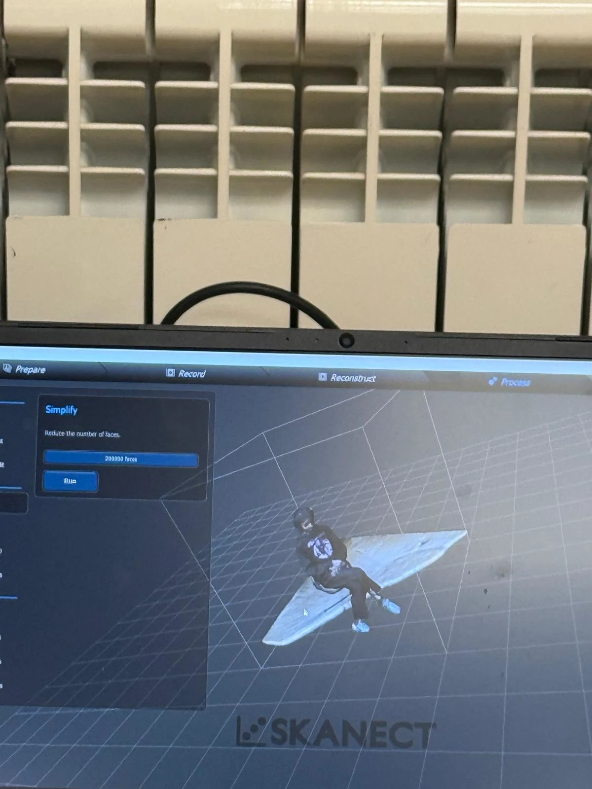
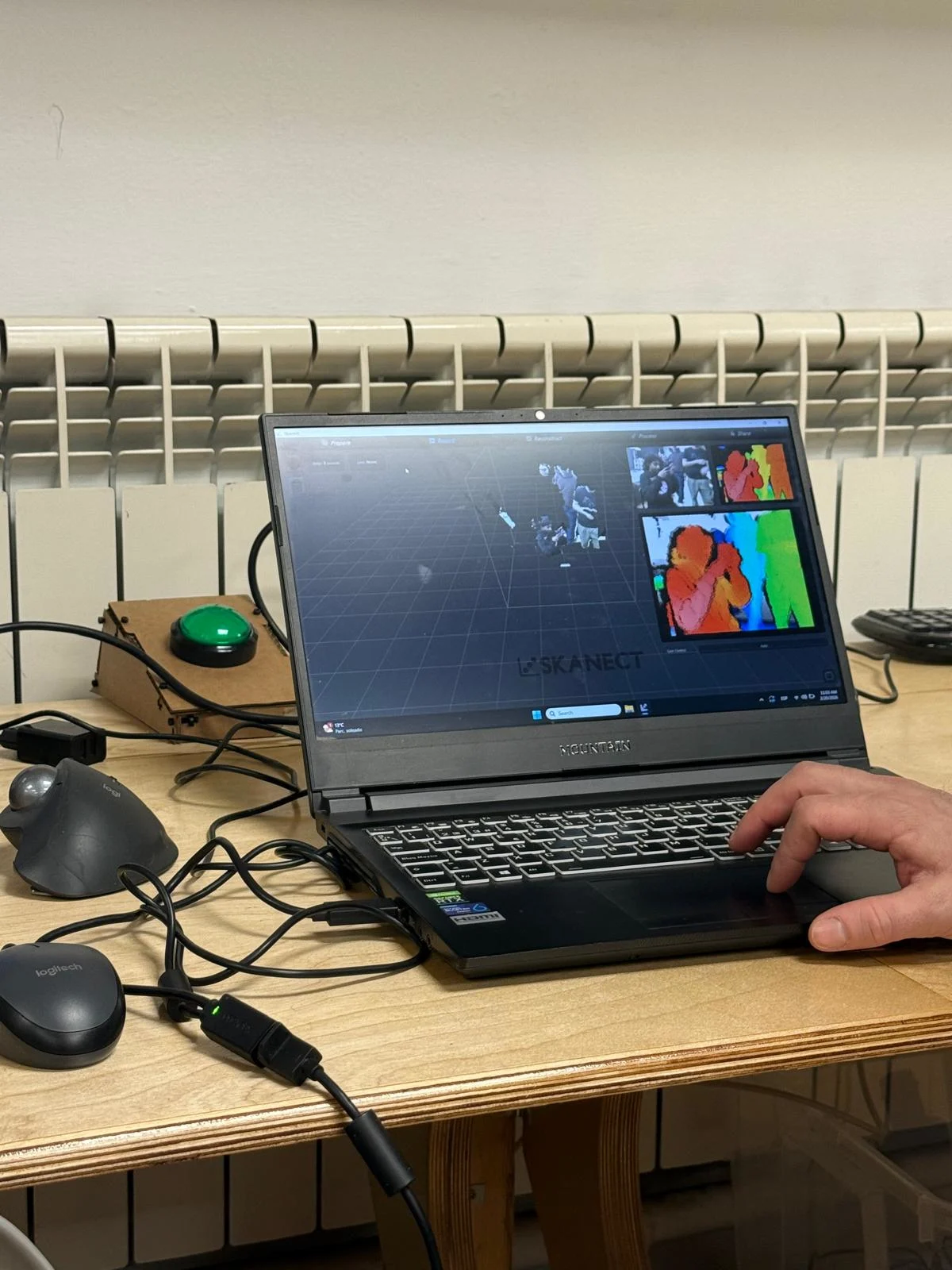
and then we scanned me!
we then saw how to process the scans and create 3D models from them.
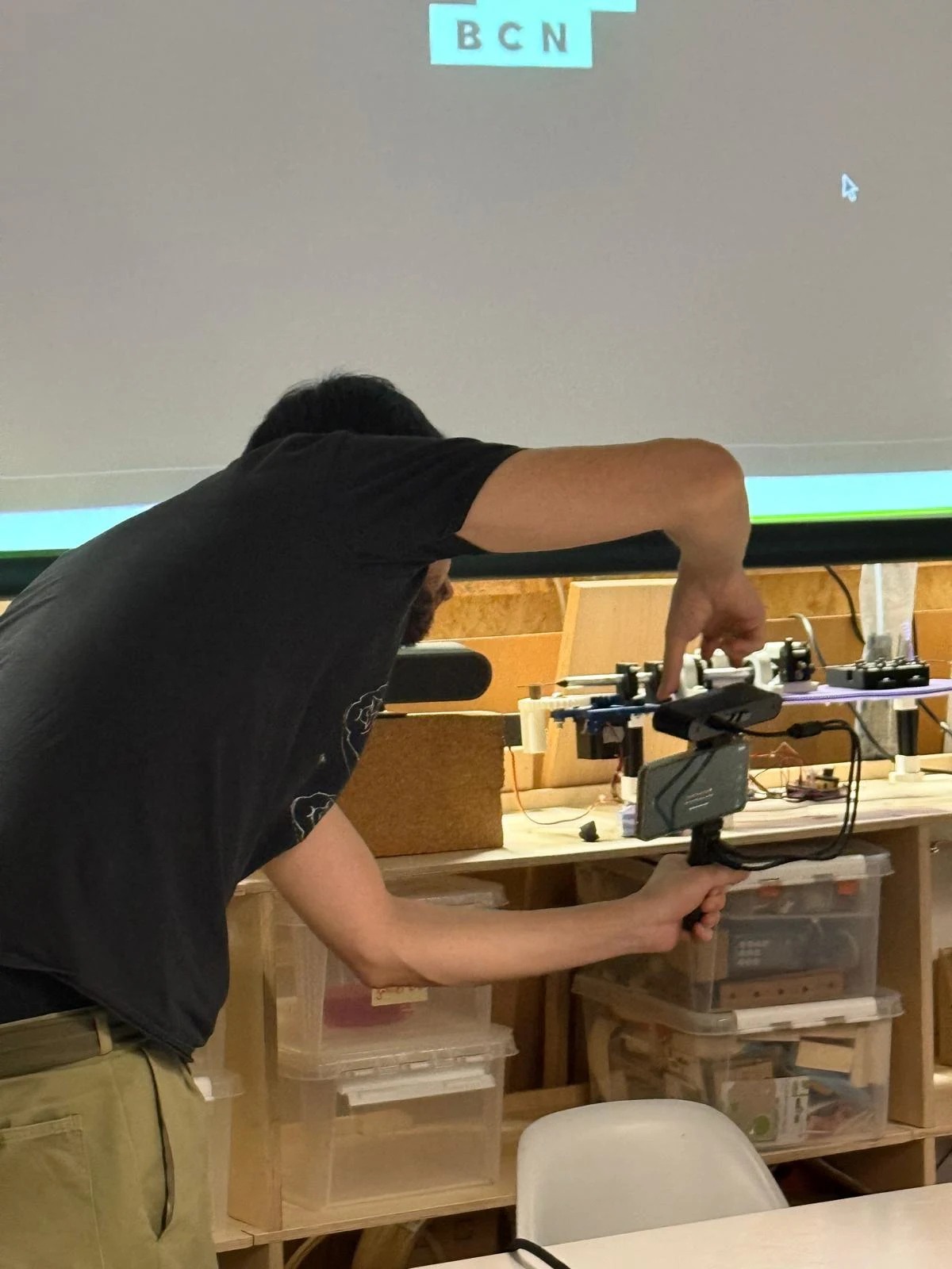
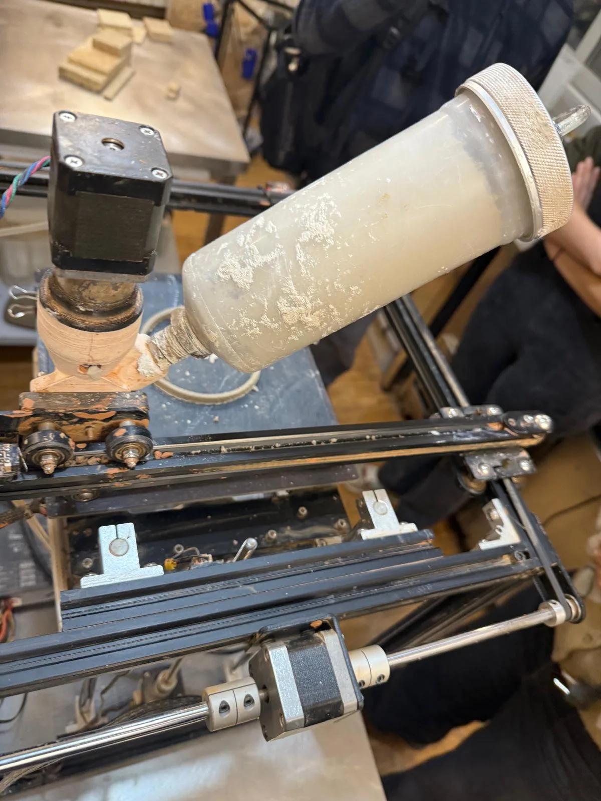
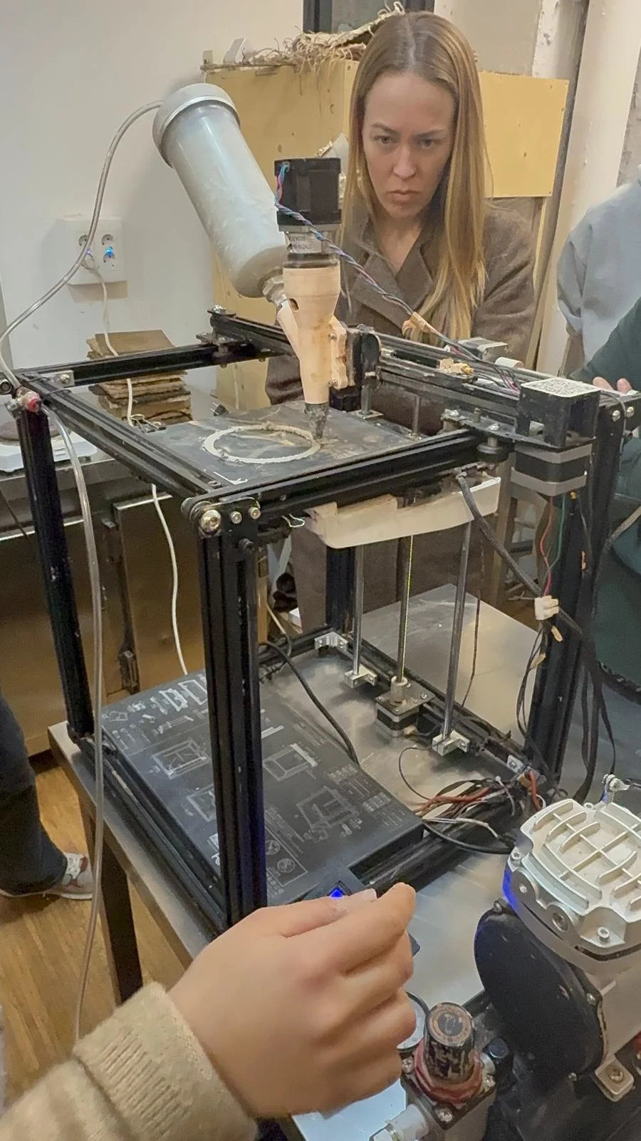
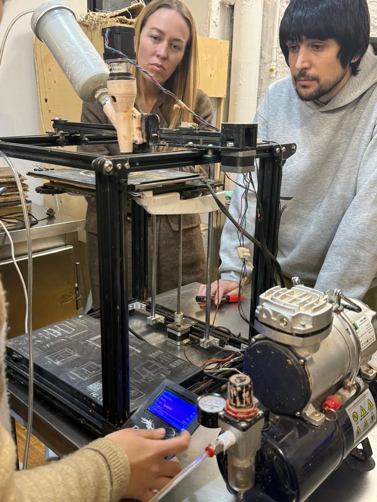
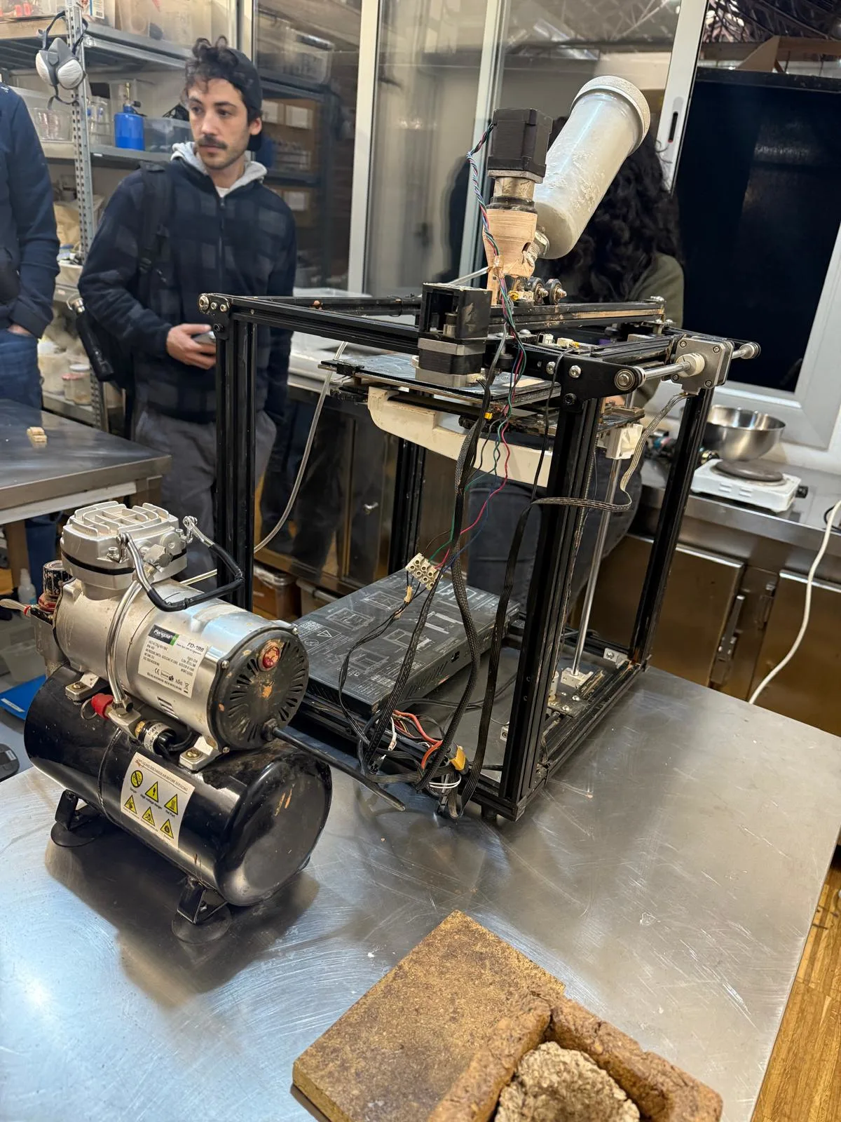
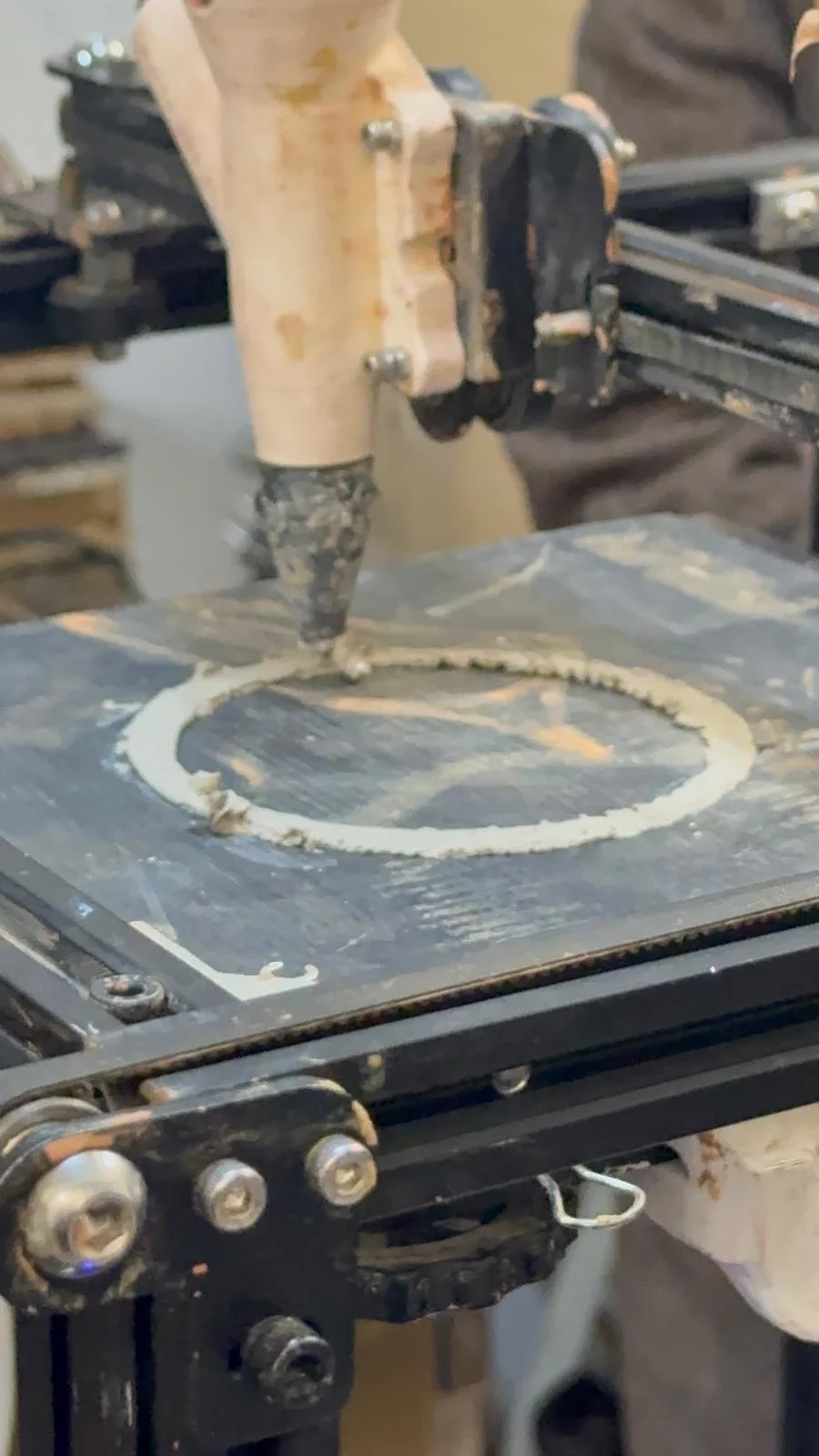
Paste Printing
We also had a session on paste printing, which I found very exciting. I am interested in eventually converting my old Ender DIY printer into a paste printer using an air compressor system, although for now I am mainly observing and learning from the process.
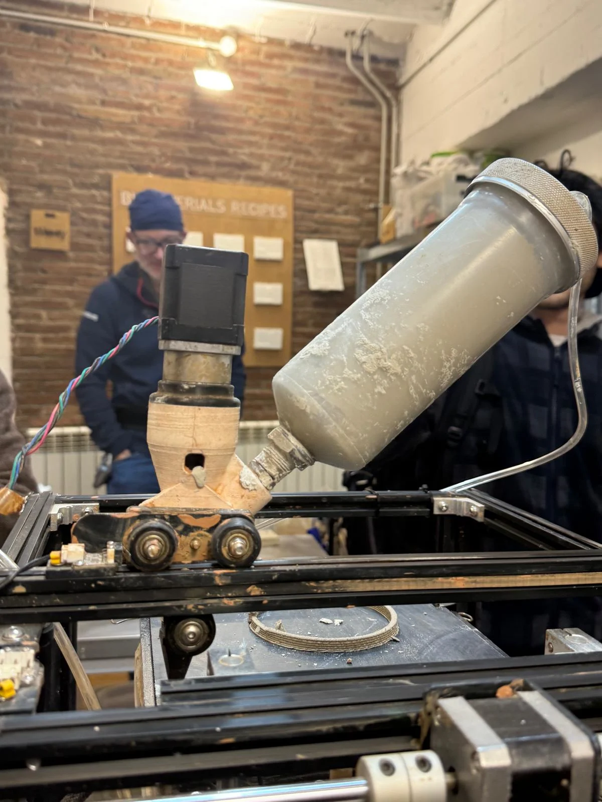
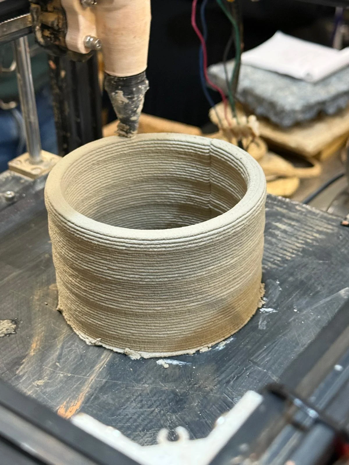
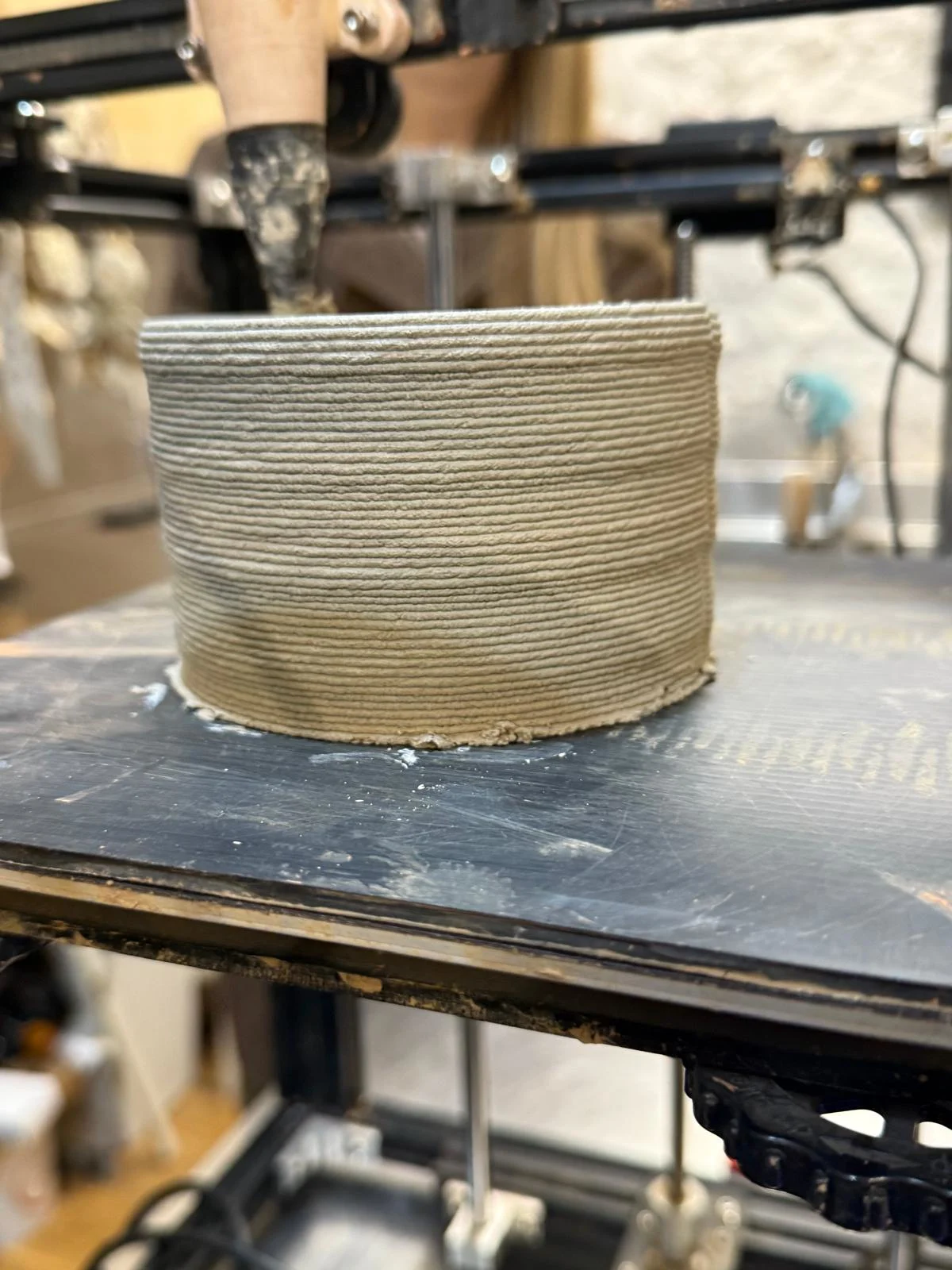
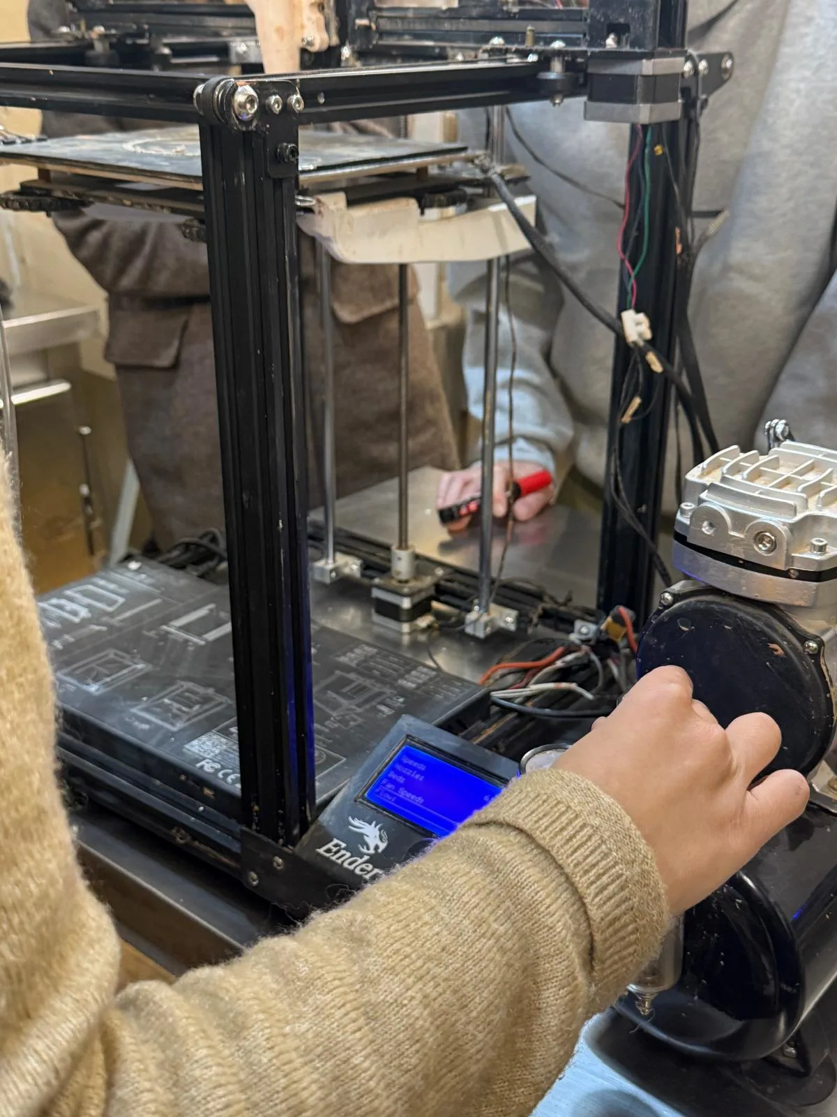
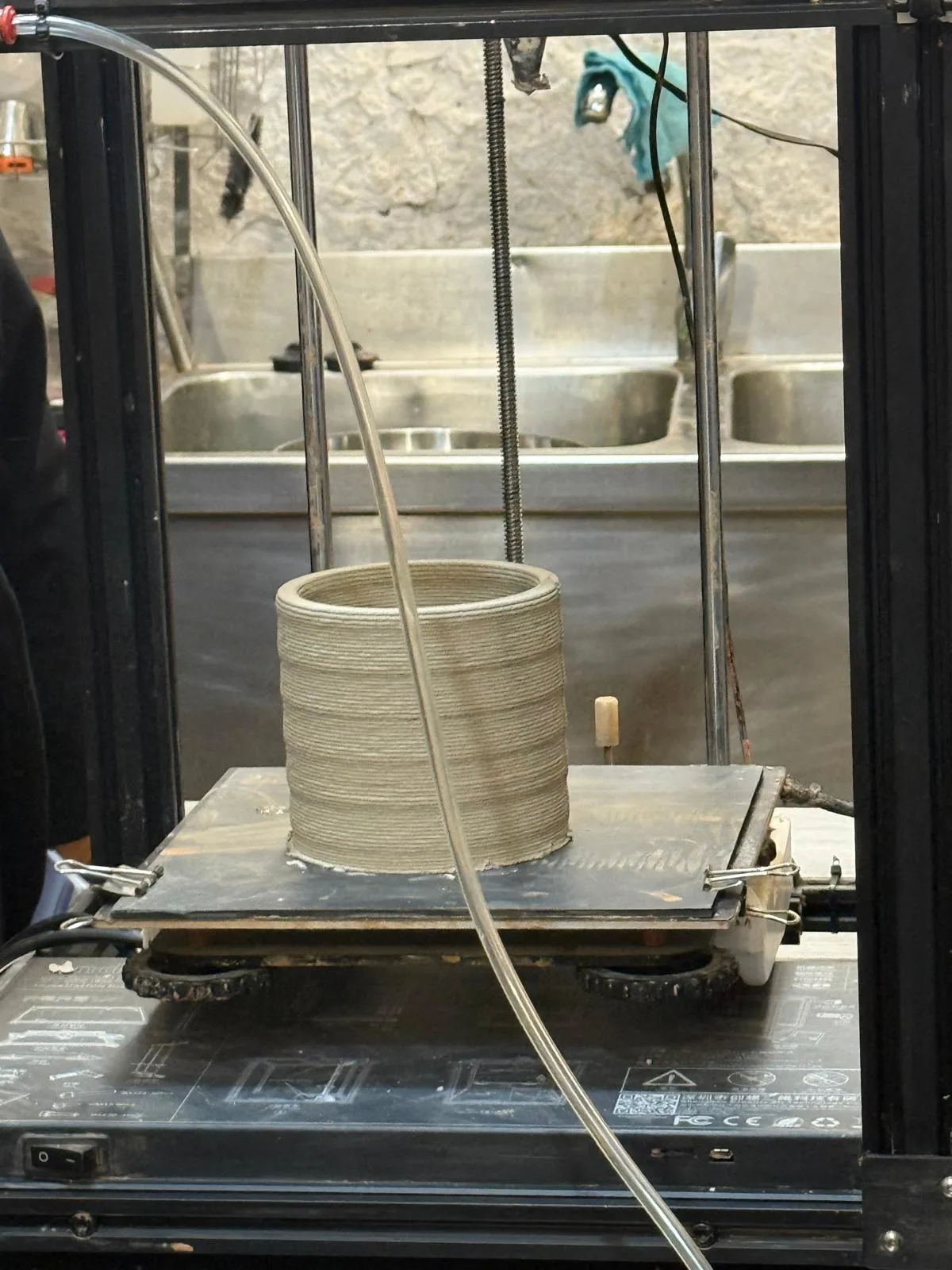
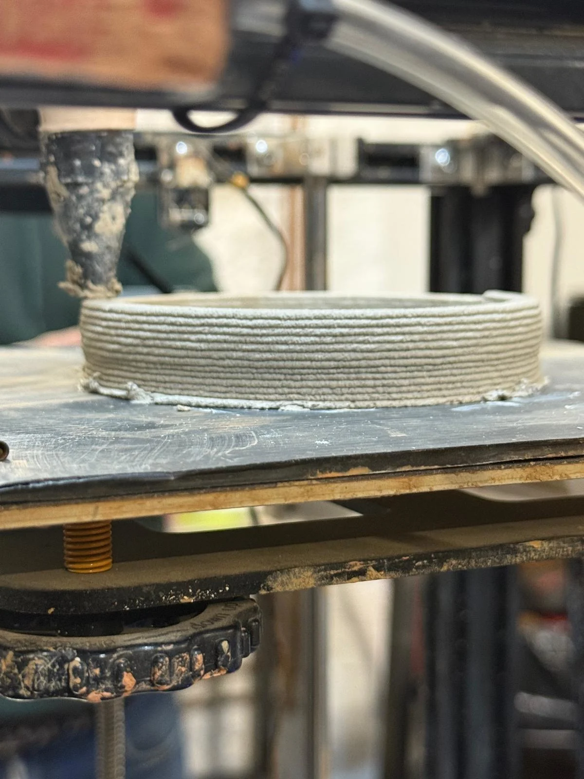
Yield Strength and Pressure
One important thing to consider in paste printing is yield strength, which is the pressure needed to push the material forward. The right pressure depends heavily on the material mixture, so testing by feel and repeated experimentation is necessary to find the correct settings.
Clay Extruder Kit
We learned that there is a clay extruder kit where many of the parts can be fabricated, while some parts can be purchased separately. Teflon tape can be used around threaded pipe connections to help prevent air leaks.
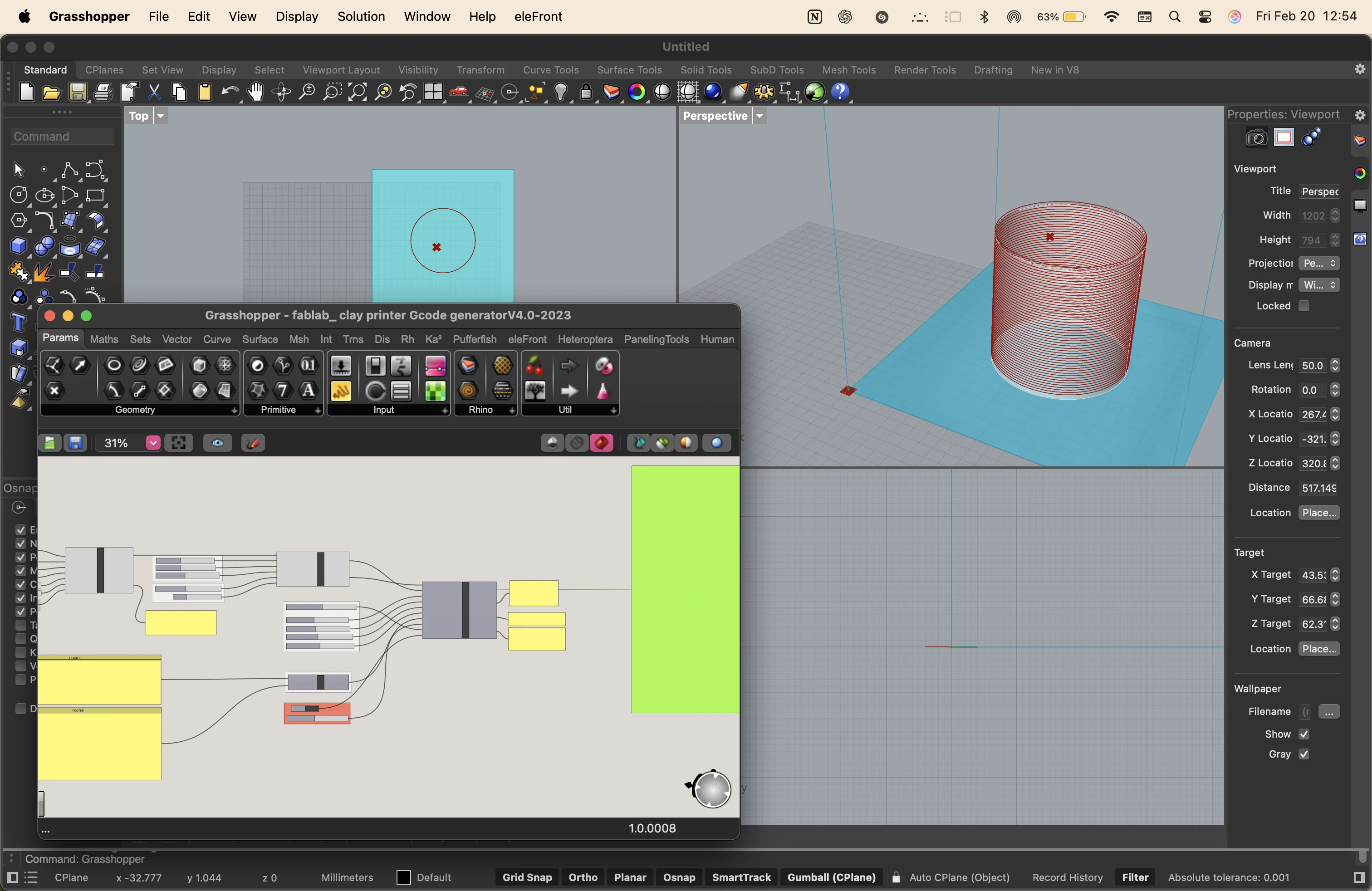
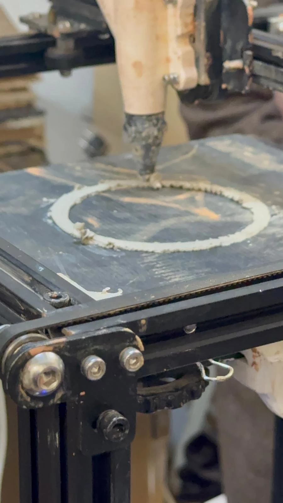
G-code in Paste Printing
We reviewed the basic structure of G-code, which generally includes a header, a toolpath, and a footer. In paste printing, the G-code can be controlled more directly so that movements can be slowed down and adjusted carefully depending on the behavior of the material.
Key Takeaways
- 3D scanning turns real objects into point clouds, polygons, and meshes.
- Triangulation and binocular vision are important principles in scanning.
- FDM and SLA are two major 3D printing methods with different workflows and material systems.
- Layer height, infill, supports, and orientation strongly affect print quality and strength.
- FDM parts are stronger parallel to the layers and weaker across them.
- Photogrammetry depends on good lighting, many photos, and careful image capture.
- Paste printing requires control over pressure, material consistency, and machine movement.