assignment
• write and test a program for an embedded system using a microcontroller to interact (with input &/or output devices) and communicate (with wired or wireless connections)
• browse through the data sheet for a microcontroller
extra credit: assemble the system
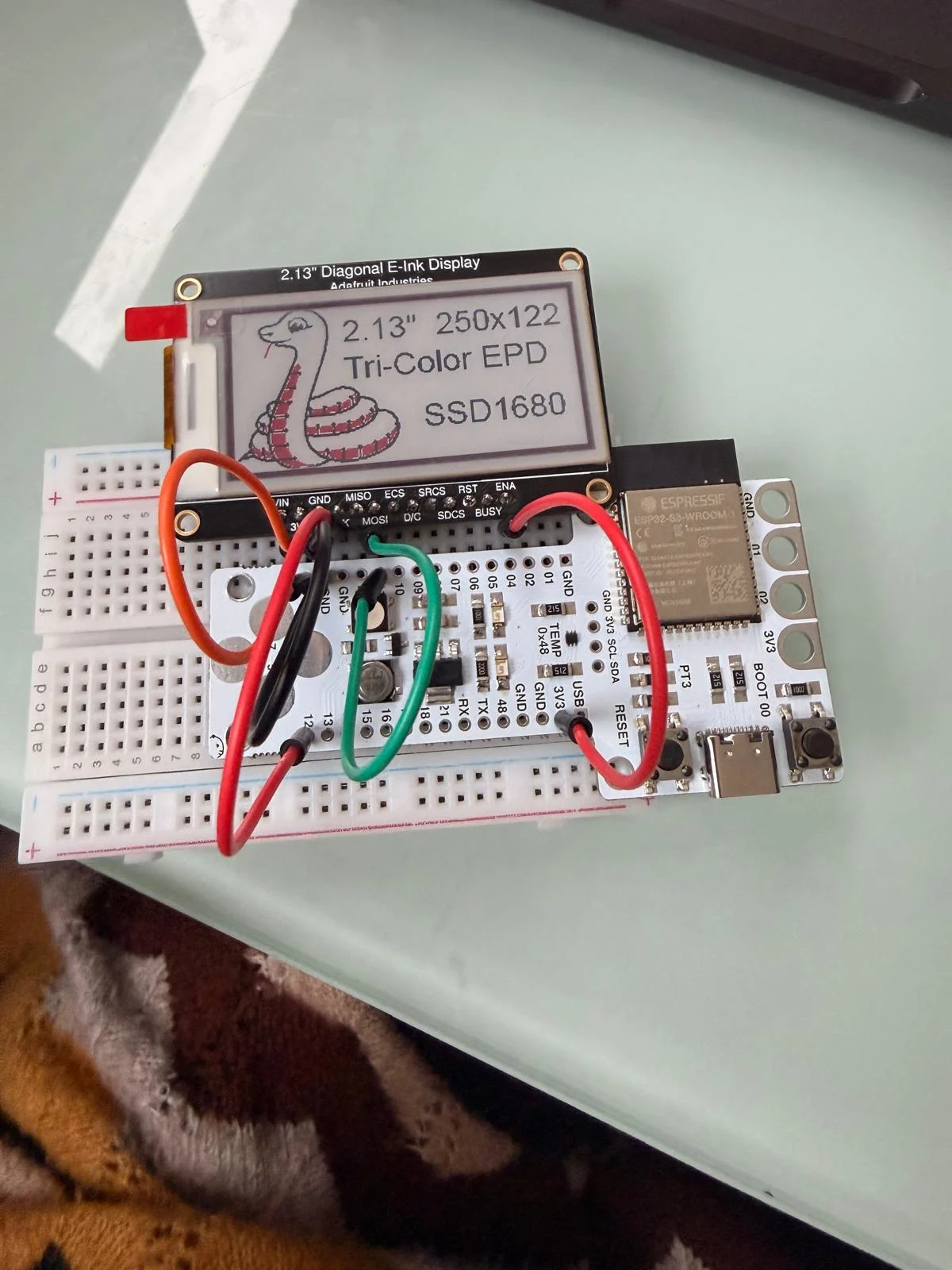
for this week, I want to connect to an OLED screen
goals
connecting to the barduino
connecting the display to barduino
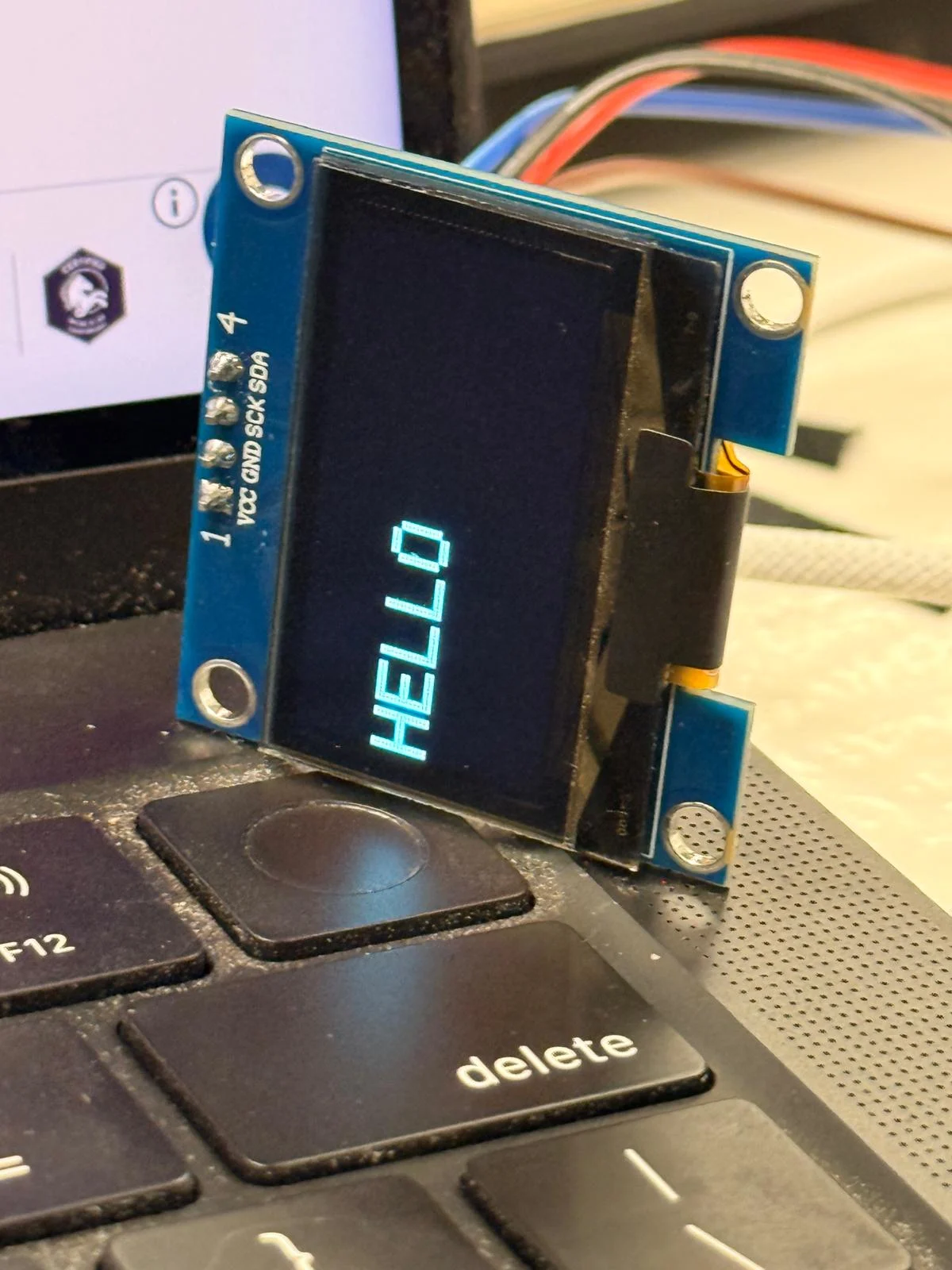
display "hello"
what i need
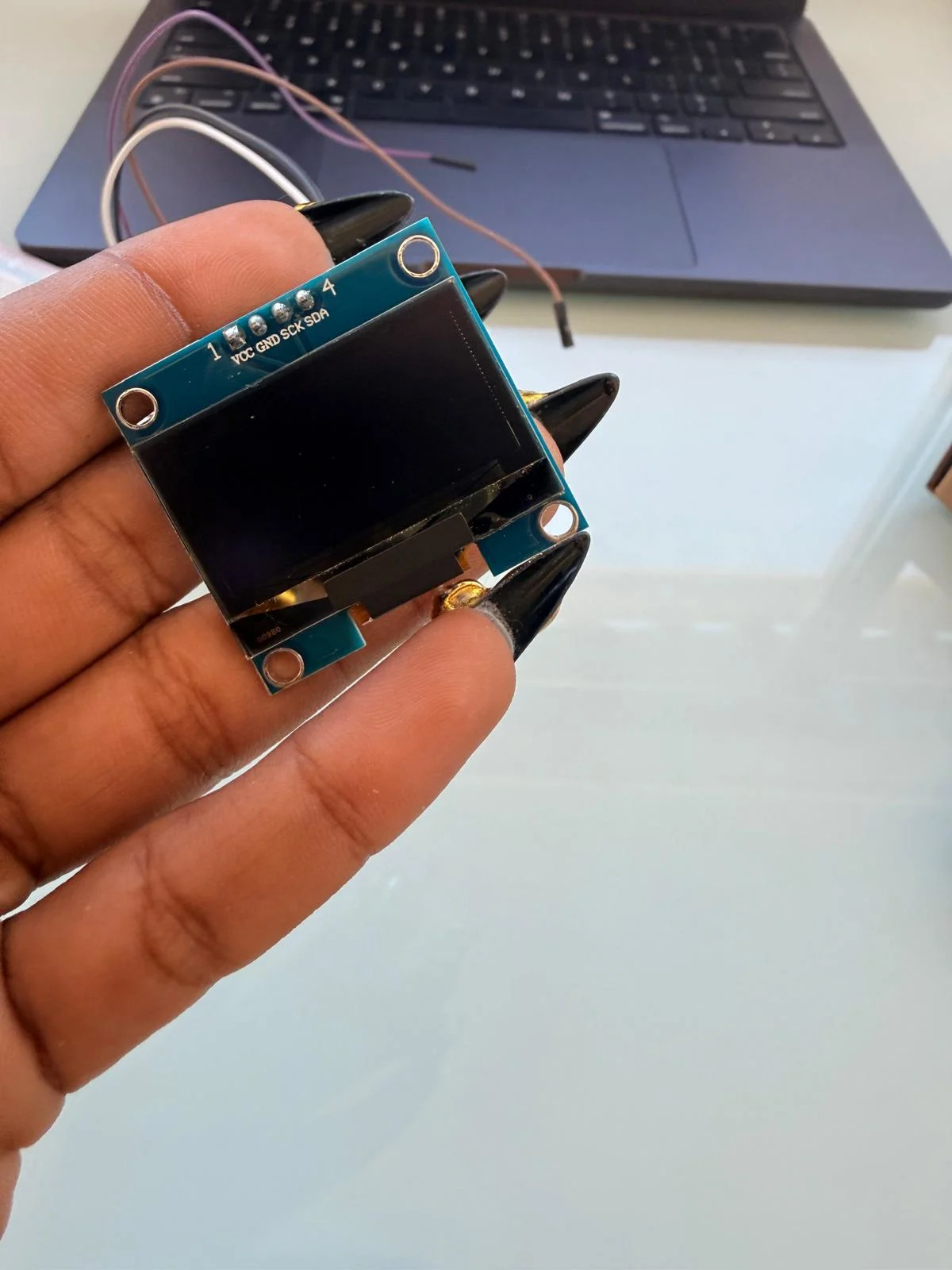
- OLED display
- barduino
- programming environment (Arduino IDE)
- breadboard and jumper wires
connecting to the barduino
the LED on the Barduino on pin 05 lights up when I connect it to my laptop with USB-C
tried a test code
                  const int LED_PIN = 48;   // built-in Barduino LED

                  void setup() {
                  pinMode(LED_PIN, OUTPUT);
                  }

                  void loop() {
                  digitalWrite(LED_PIN, HIGH);
                  delay(500);
                  digitalWrite(LED_PIN, LOW);
                  delay(500);
                  }
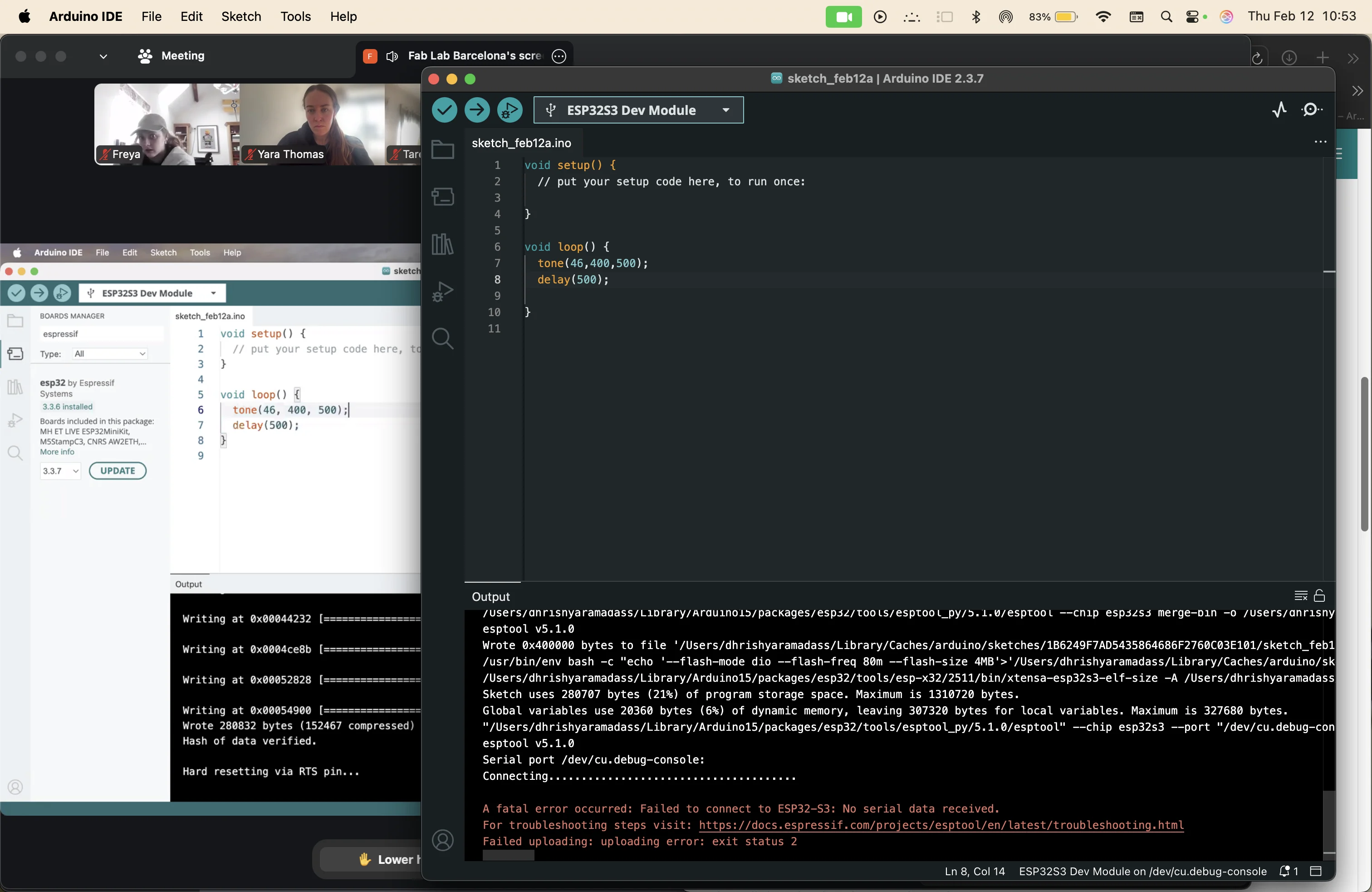
error: could not find a valid board
error: didn't specify pin
error: failed to connect to the board
I asked chatGPT for help since I was stuck on the error messages.
enable USB CDC on Boot
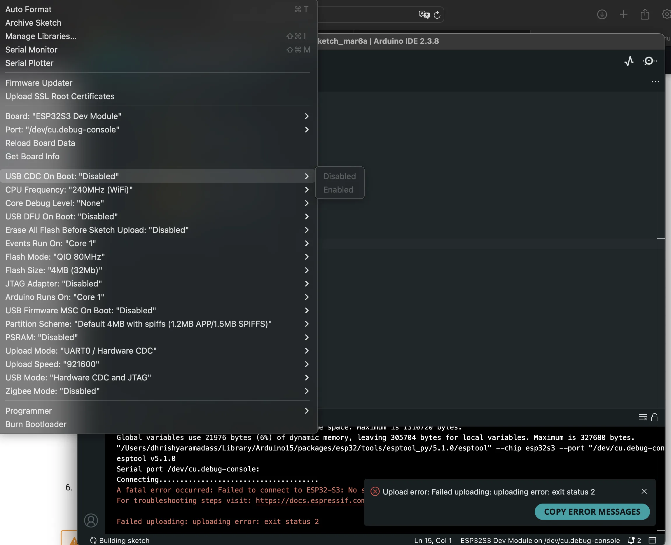
on the top bar, tools -> port -> select your board
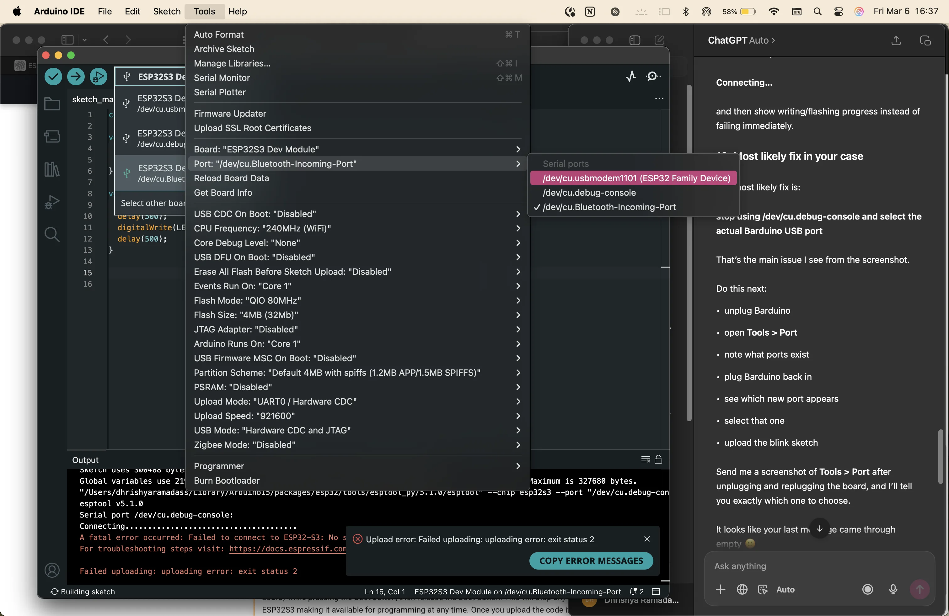
do this by disconnecting and connecting the ardiono to identify the correct port to select the new one
also added pin 48 because i accidentally had deleted that line of code earlier.
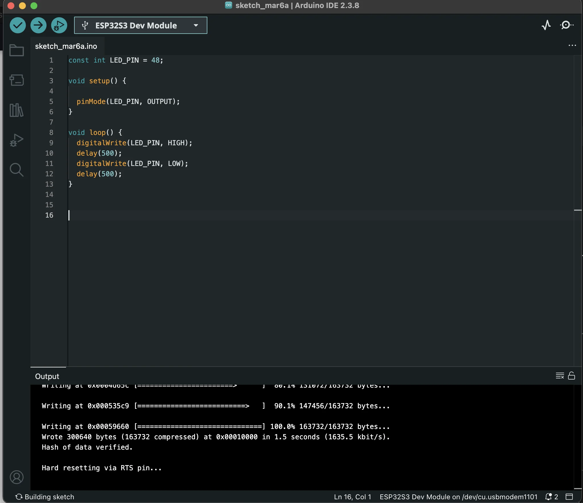
the board is connected and the light is blinking.
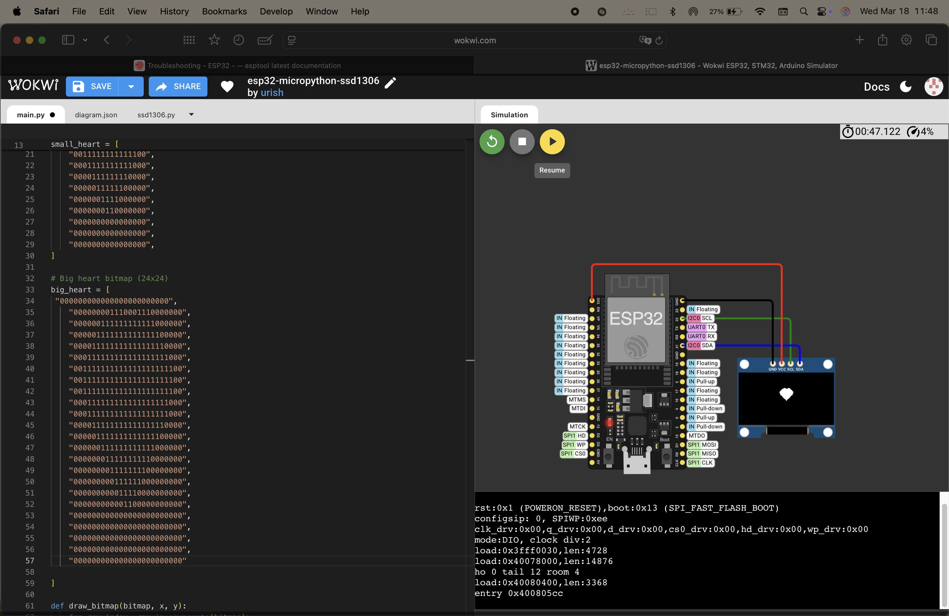
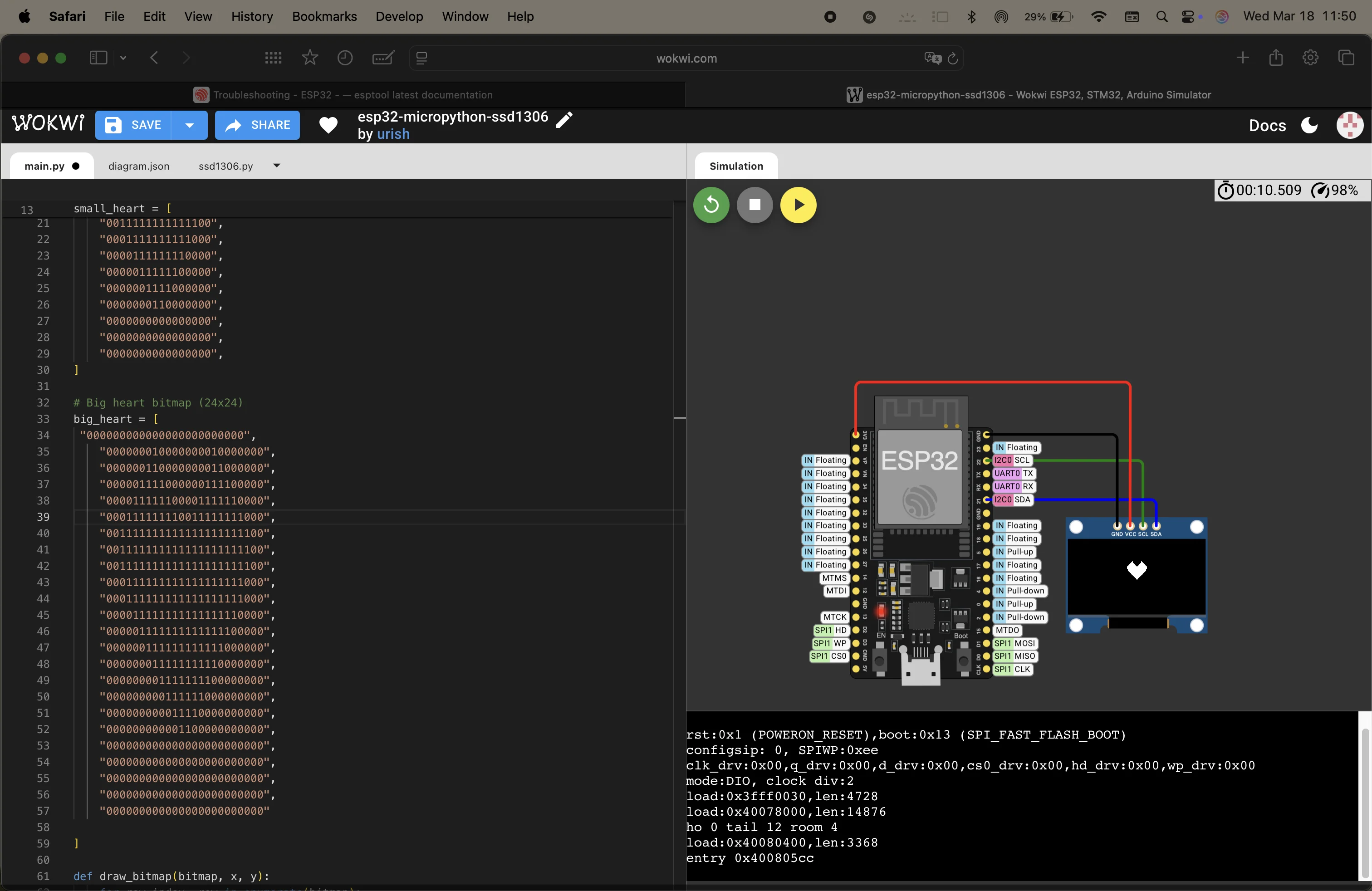
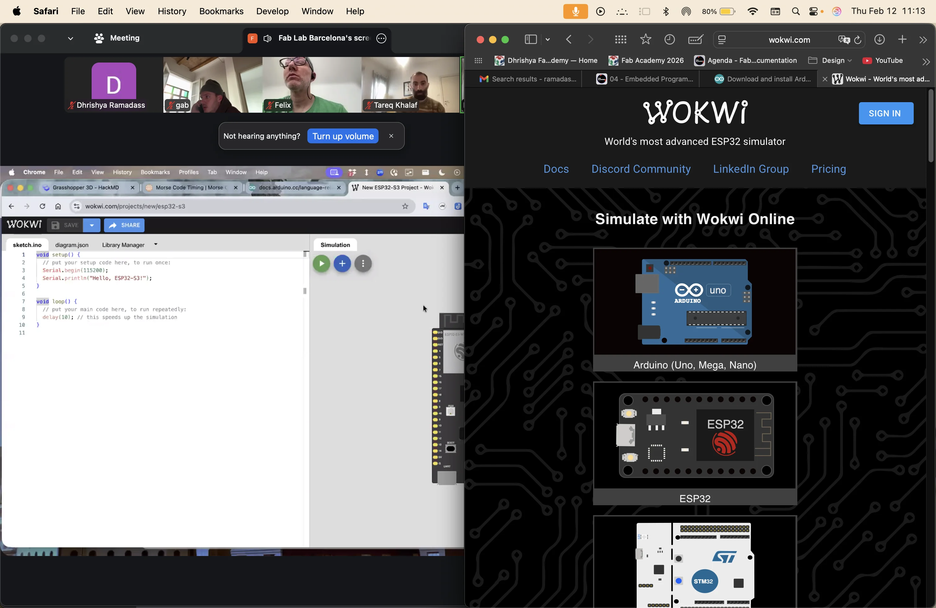
digitally simulating a heart with wokwi

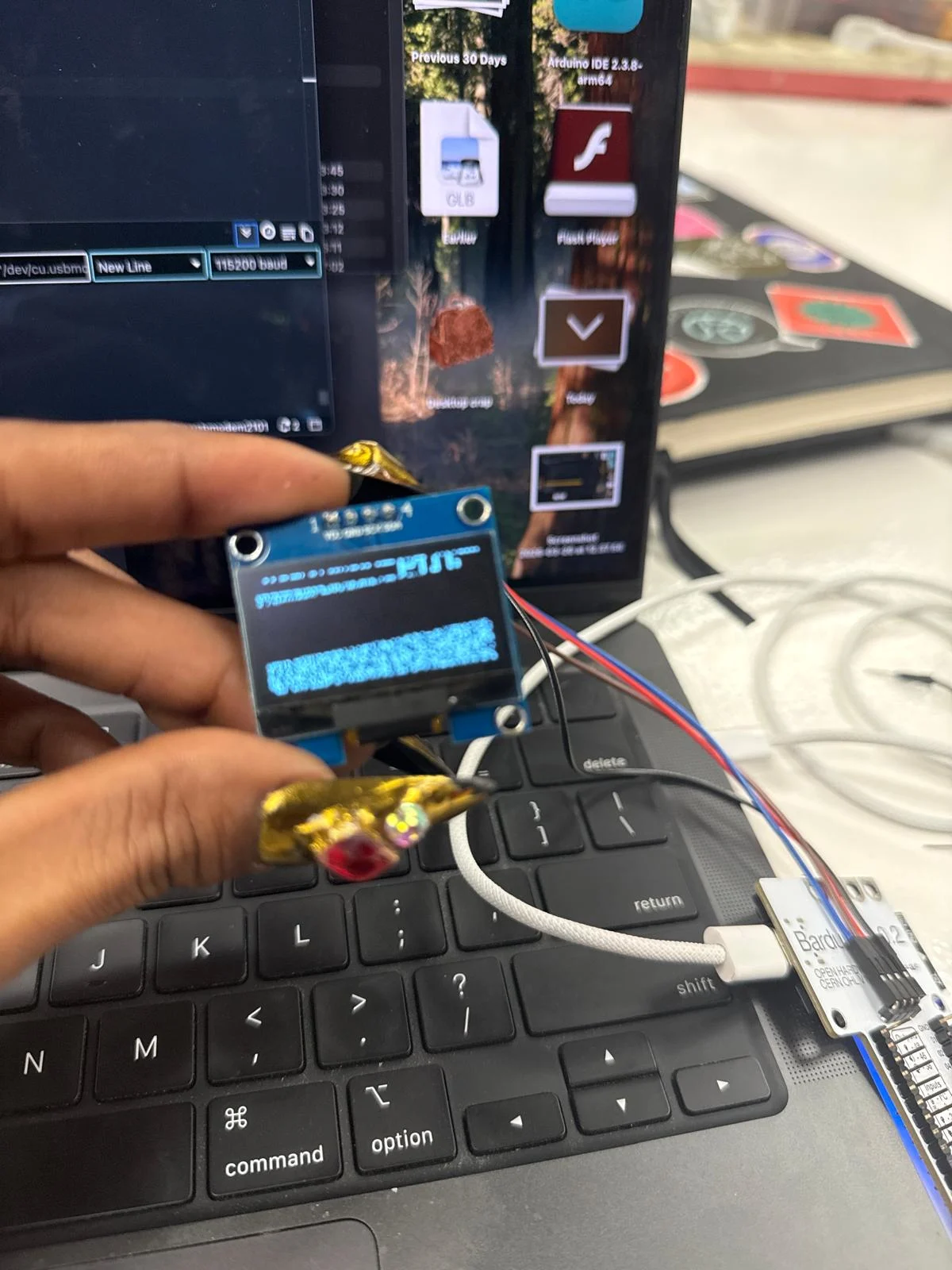
soldering pins to the OLED display and the Barduino
p.s i spent a few days trying to use wires without soldering pins- and failing miserably. none if the hacks work and I agree that breadboard has too many problems and soldering pins has a way higher success rate.

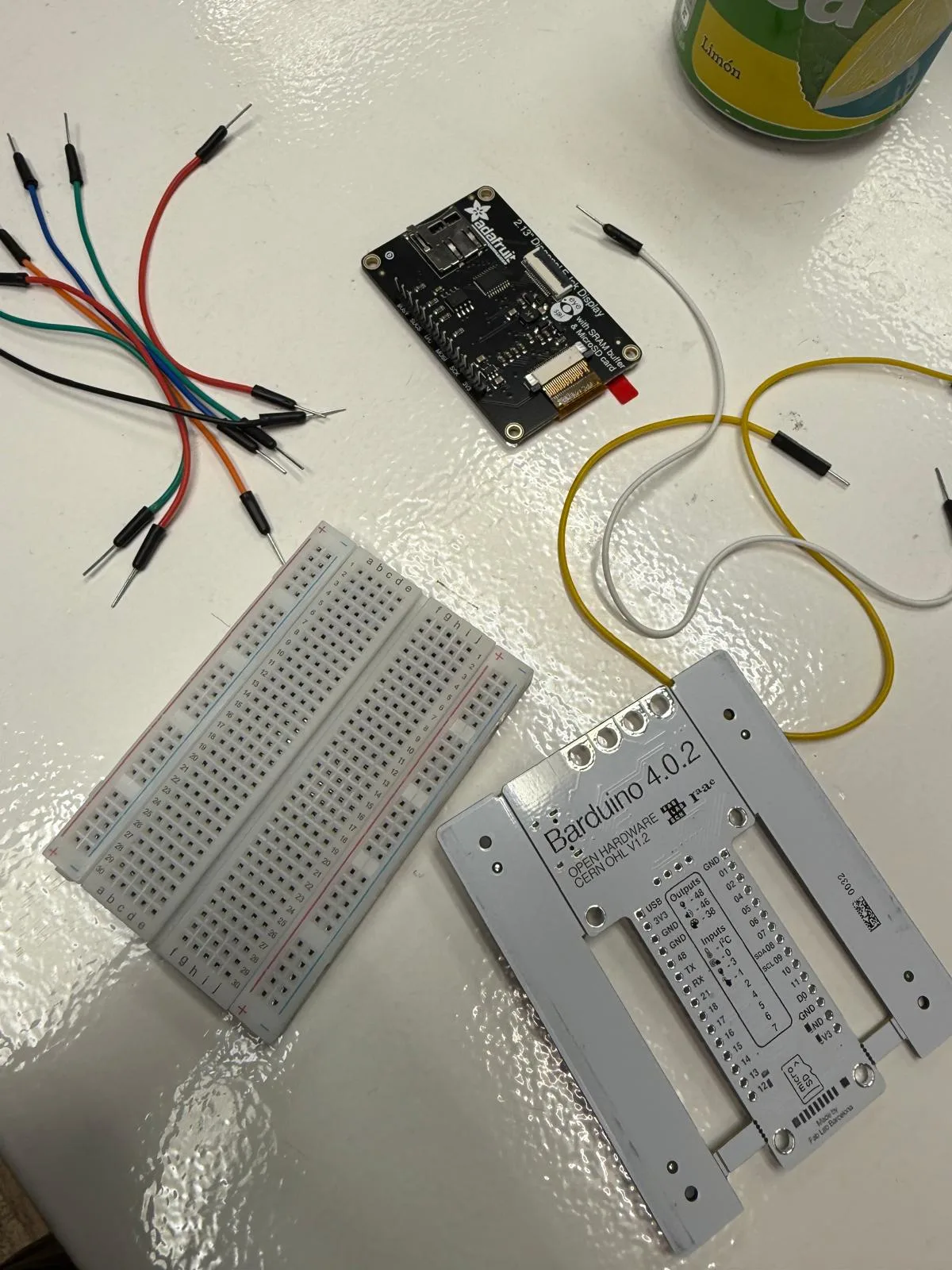
once i soldered the pins, everything worked much better. I connected the OLED display to the Barduino without any issues.
I finally figure out how to display "Hello". I had to download the Adafruit SSD1306, SSD1106 library and the Adafruit GFX library.
I connected the pins of the oled display to the I2C connectors already present on the Barduino as follows:
3V3 - 3V3
GND - GND
SDA - SDA
SCK - SCL
                      //arduino code

               #include
                #include
                #include

                #define SCREEN_WIDTH 128
                #define SCREEN_HEIGHT 64
                #define OLED_RESET -1

                Adafruit_SSD1306 display(SCREEN_WIDTH, SCREEN_HEIGHT, &Wire, OLED_RESET);

                void setup() {
                  Serial.begin(115200);
                  delay(200);

                  Wire.begin();

                  if (!display.begin(SSD1306_SWITCHCAPVCC, 0x3C)) {
                    Serial.println("SSD1306 not found");
                    while (true);
                  }

                  display.clearDisplay();
                  display.setTextSize(2);
                  display.setTextColor(SSD1306_WHITE);
                  display.setCursor(20, 25);
                  display.println("hello");
                  display.display();
                }

                void loop() {
                }
I wanted to read the datasheets of the microcontroller I am using, and the one commonly used for other projects in the fablab.
i read the datasheet of the ESP32 (since it is on the barduino given by the fablab)
These datasheets are heavy with information. Like an encyclopaedia. I will have to keep referring to them based on the projects that I work on.
what I learned from the esp32 datasheet
The ESP-32-WROOM-1 is a super power ful microcontroller unit that has wifi and bluetooth built in for communication. it is kind of like a tiny computer for hardware systems. in the module, you can find a processor, hardware for wireless communication, memory, input and output pins - GPIO, connectors for sensors, i2c for displays, motors and other electronics.
it is super poweful especially compared to an auduino uno for example. it uses a dual core xtensa processor, which allows it to perform multiple tasks simultaneously and handle more complex applications. This makes it better for multitasking, audio and image processing and even some lightweight AI applications. This makes it perfect for installation design as I will be using it for my installation.
the esp 32 also has different types of memory. ROM for storing permanent system code, SRAm for working memory when the chip is running, Flash memory for uploaded programs and optional PSRAM for extra memory for heavy stuff like graphics and machine learning.
one of the best things about it is the variety of communication interfaces. GPIO to interact with LED's sensors, buttons, actuators, etc. ADC for converting voltages to digital values to read potentiometers and temperature sensors, PWM for simulation of analog behaviour like brightness control, speed of motors, etc. the chip also has spi connections for touch interfaces and complex displays. and i2c to connect to OLED's , uart for serial communication and a way to program it,and even i2s for audio devices. this makes the esp 32 versatile to almost any external input and output components.
the esp32 usus 3.3v power. any higher can fry the chip. it has some power saving modes like modem sleep, light sleep and deep sleep- which is useful for efficient power consumption in long term systems and monitoring devices.
it also has a boot system that determines whether it runs the stored program or enters the mode to upload new code. this is very important to understand when making custom pcb's with it.
it is a compact and efficient brain with a range of capabilities and i intend to use as many of them as possible.
thoughts and reflections
working with code and electronics is a very precise and accurate art that includes trial and error, debugging and a lot of patience. it can be useful to understand the components before using them in complex systems. i spent this week exploring different components i could use for my project like the pulse sensor, an oled screen, an e-paper module, an i2c connector with led display, and whatever electronics were lying around in the lab. it is very very imporrtant to solder connector pins to components that need them inclusing the bardiono. or they will just not work. there will always be a loose connection with a breadbord.
here is the link to the group assignment page group assignment week 4
reflection
for the group assignment we connected a ATtiny 420 board and sent signals to test it. I was interested in the physical connections of such a small chip and make a mini circuit to test blinking LEDs. I tried to contribute by reading through the datasheet for the component and troubleshooting wiring and connections.
This week was very important to me as it marks the beginning of learning things I have no experience with. In the local class, Danny taught us about the core elements of a PCB. It fascinated me how simple and complex it can be based on the functions that it needs to do. It is really important to understand the components that we use, read the datasheet, and refer to it whenever questions arise. It is also helpful to make ChatGPT memorize the datasheet and ask questions about the component by adding the datasheet files into the chat to train it. Be aware that the context window can be quite small, so it is not viable for long-term use, but it helped me understand the components for now.
Before this week, I associated coding with complex software or front-end design execution tools. Now I understand that code is simply a translator that people can use to communicate with computers and make computers communicate with each other. Every coding language moves closer to human understanding and is ultimately broken down into ones and zeros in infinite combinations.
It was useful to understand how programming affects interaction with the user. Timing, response, movement, and other behaviors can create emotional and physical reactions. It feels like poetry translated into tangible expression and can be used to create relationships and connections with the person interacting with the system.
Week 4 – Electronics Programming
Class notes from the global lecture and local sessions.
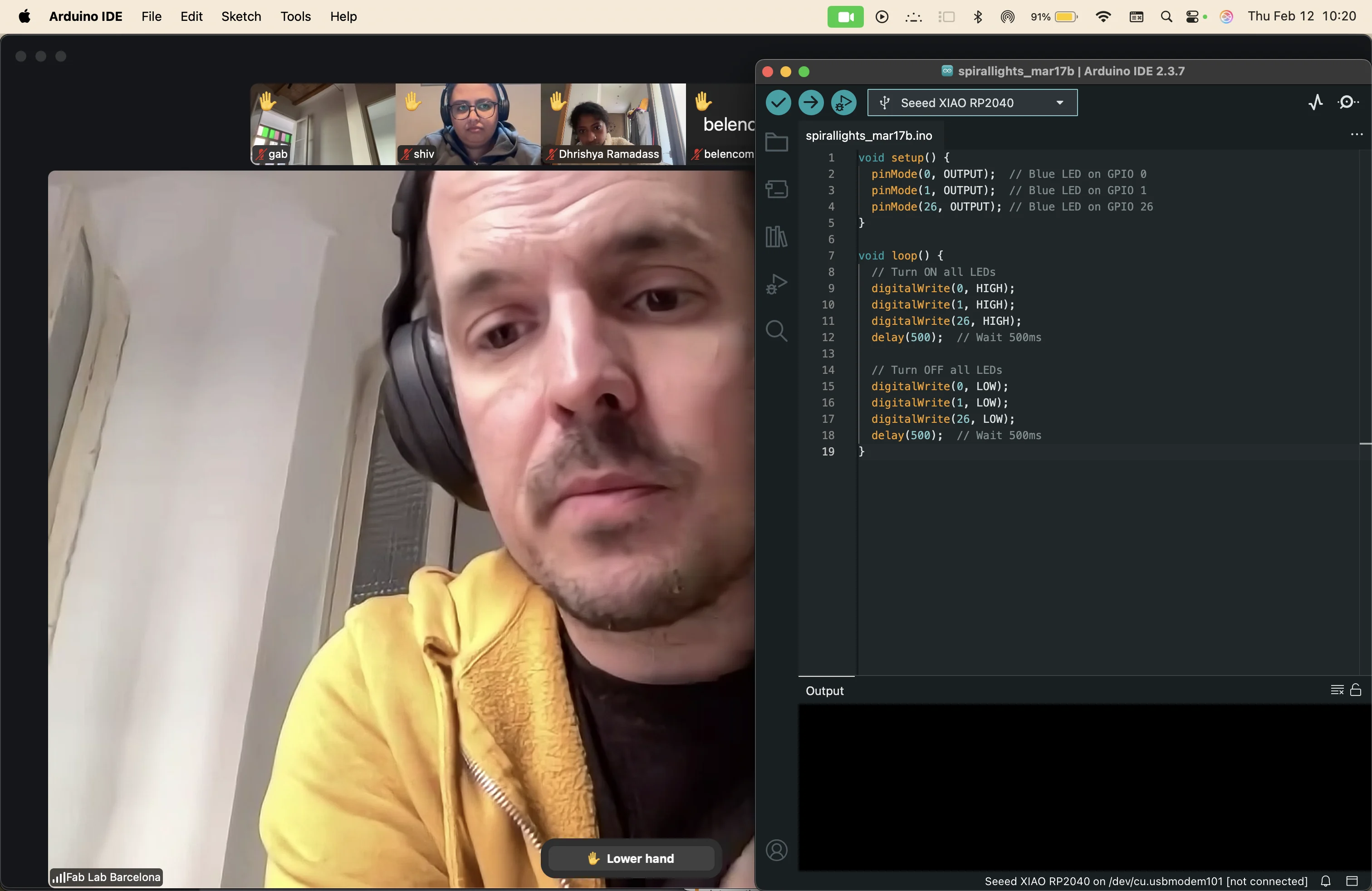
dani shows us wokwi to digitally simulate circuits and microcontrollers.
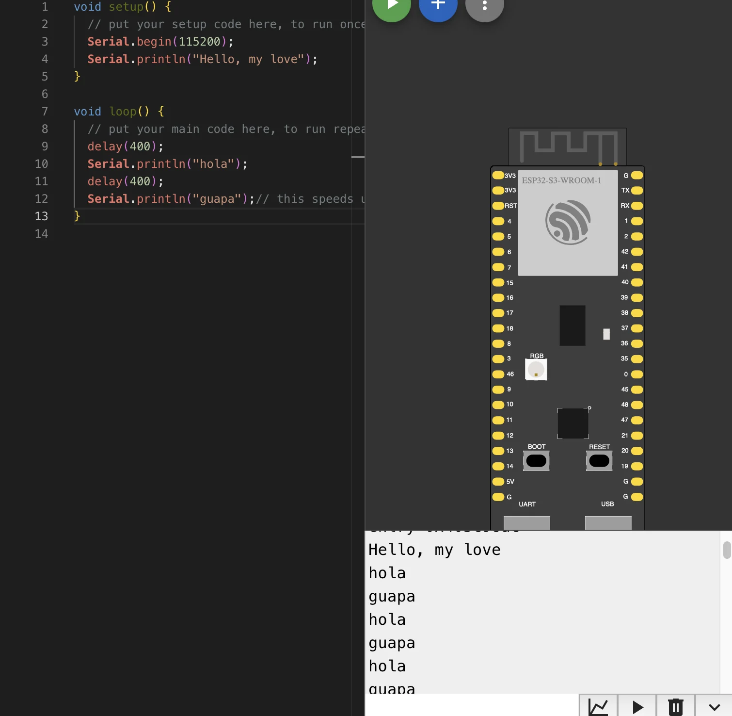
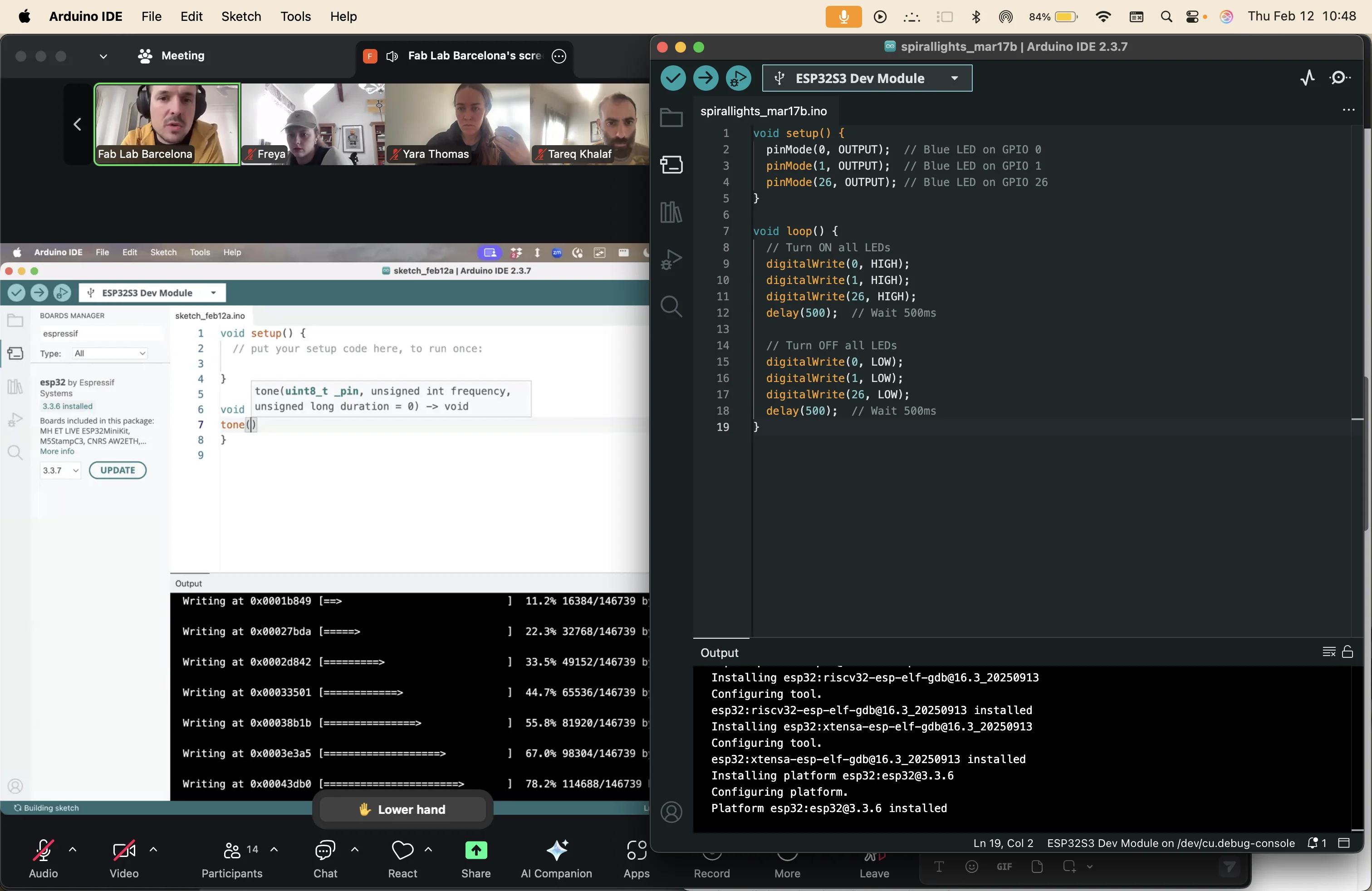
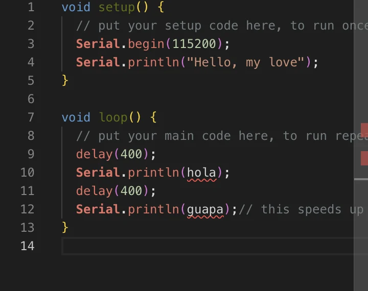
the code
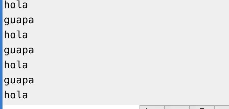
the output