7. Computer Controlled Machining
Group Assignment
This week’s group assignment involved completing safety training and testing some of the key features of the CNC machine in our fab lab. The following is our group documentation where we used our lab’s Axiom Precision CNC machine.
Prior to this week, I only had a basic understanding of how CNC machines work.
Potential Risks
One thing I learned is that ensuring safety is not impossible, but requires careful management to avoid potential damage or injuries.
To promote safety, the use of the CNC machine was sectioned into meet times so our professor could work alongside us. This maintained a safe working environment for students.
Design
This week, I decided to make a storage box. I used Autodesk Fusion to design this box, as it is a tool I have explored and used in the past.
For this design, I decided to include some connectors so that my final design would not need glue to hold it together.
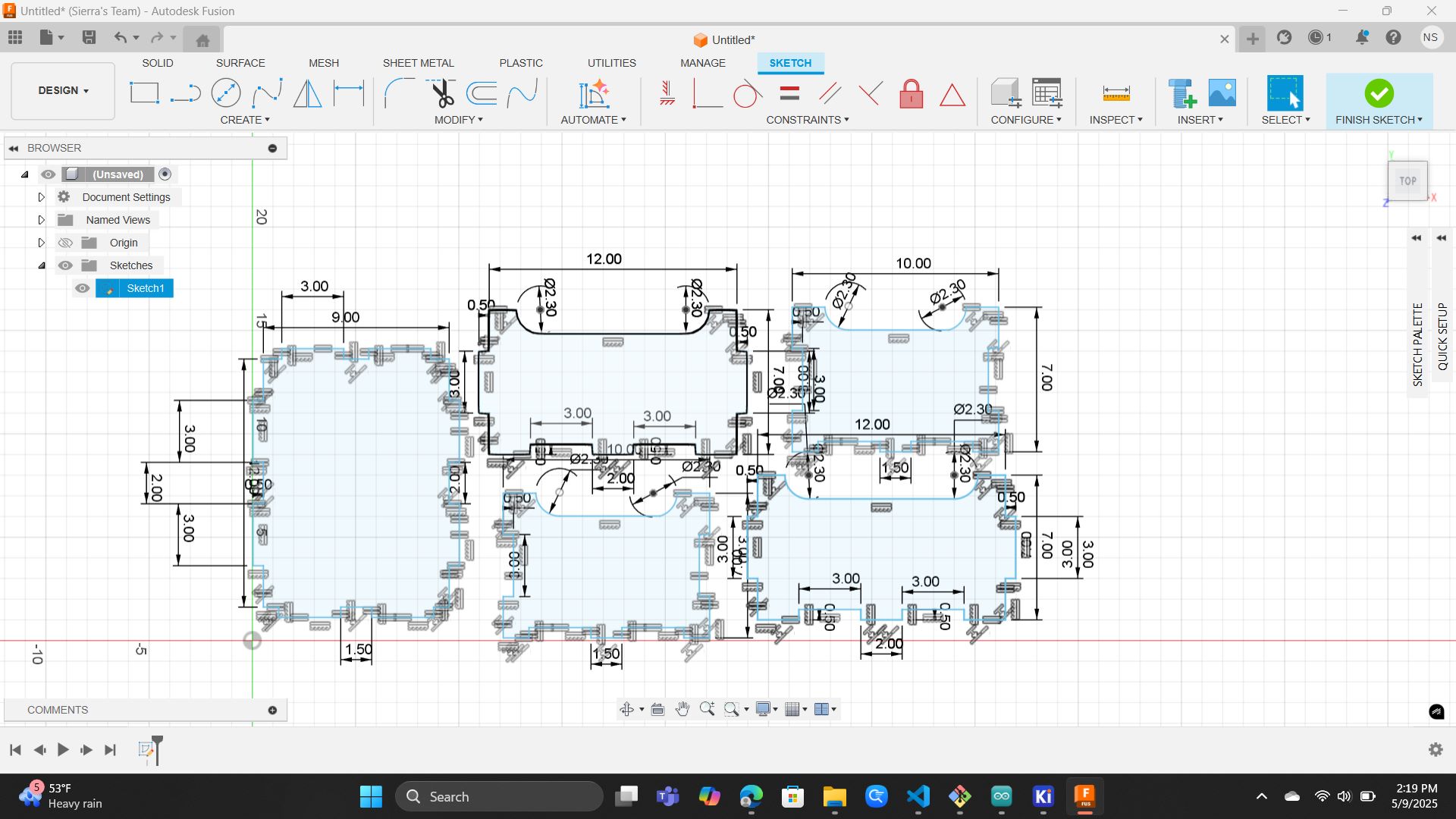
When starting up Autodesk Fusion, I first changed the scale of the document to inches
In Fusion 360 to design my pieces, I started with either a 9x12 rectangle (bottom), a 10x7 rectangle (front+back), or a 12x7 rectangle (sides).
Making Bottom
To make the bottom, I first made a 9x12 rectangle and added a 3x1/2 inch rectangle to each side twice.
Because the width of the wood is 1/2 inch, I added a 1/2 inch sketch dimension.
Dimension Tool Symbol

I then used the equal constraint to set each connector to the same size.
Equal Constraint Tool

The distance between the connectors on the 12 inch side is 2 inches, while the 9 inch side has a 1.5 inch distance between the connectors.
Making Front & Back
To make the front and back, I first made a 10x7 rectange.
These pieces have the connector cut out of the shape instead so both the bottom and sides can attach into it. A quick side shape overview: The sides have the same length dimensions as the bottom if you added the connector width of 1/2 inch. the sides of the pieces stretched outwards while the bottom, like the front and back, had two connector shapes cut out from it.
Final Fusion 360 Sketch
Machining Preparation
In our class lab session, we used V Carve Pro to create the design files compatible with our CNC machine. We then ran design files compatible with the CNC machine. We ran tests by cutting sample pieces to see how different slot dimensions would fit together.
To prepare the bracket shelving design for CNC cutting, I exported each sketch from Autodesk Fusion 360 as a DXF file. Then, once in Adobe Illustrator, I converted the sketches to SVG format.
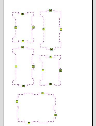
Then, import the SVG file into V Carve. To do that, select File>Import>Import Vectors. Import each SVG one at a time. After importing. I arranged the pieces to have at least 1 inch spacing between them to ensure none overlapped the edges or clamp zones.
To help the vertical supports fit into the shelves properly, I was going to use “Dog-bone fillets” in the interior corners of the slots to prevent interference caused by the round CNC bit and ensure a snug fit. I then decided to curve the bracket parts of the shelving.
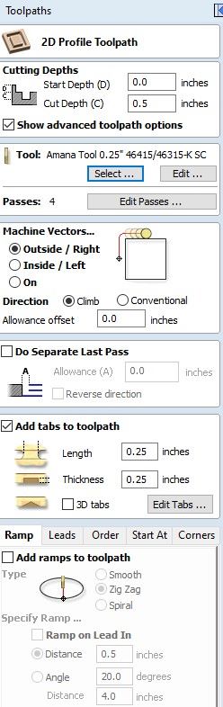
Internal Cuts: to complete internal features, create a Profile Toolpath, set the cut depth to (0.125” deep), and cut inside the vector
Outer Cuts: create another Profile Toolpath, set the same depth of 0.125”, cut outside the vector. Tabs are not needed if the design includes clearance; otherwise, add tabs. I needed to add tabs
Adding Tabs: to keep parts secure while cutting, in the Toolpath settings, enable “Add Tabs to Toolpath”. Then, click Edit Tabs and place at least one on each side of each large shape.
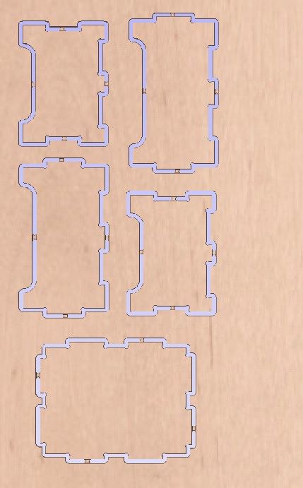
Once toolpaths are complete, use the Preview Toolpaths button to check the results. Select all toolpaths and “Save Toolpaths”.
The following is the 3D Cut Path where if you look closely, you can see the dog-bone fillets added in each sharp 90 degree corner.
Machine Cutting and Assembly
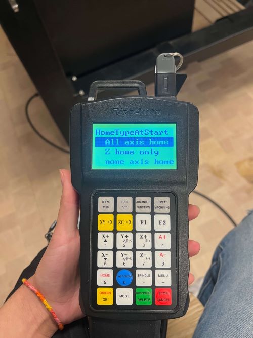
Turn on the CNC machine: locate the green power button on the side of the machine and turn it on. Plug your USB drive into the CNC controller. When told, use the yellow OK button to select “All Axis Home”, which will return the machine to its original starting position.
Secure Material: Place the 24”x48” plywood on the spoilboard. Drill screws into all corners of the plywood to secure the material.
Change the End Mill: using the two wrenches to loosen the collet, push the wrenches towards each other. Swap in the correct end mill (¼” upcut for cutting or ⅛” downcut for engraving). Then tighten the collet by pushing the wrenches in the opposite direction.
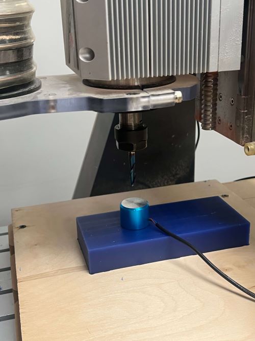
Set Z Zero with the Touch Plate: Plug in the metal touch-off plate and place it on top of the material, using the controllers X,Y,Z buttons to move the bit directly above the plate, press “Tool Set” to automatically zero the Z-axis, and unplug and remove the metal plate afterward. Though the following image is using the wax block later used in molding week, it works the same way.
Attach the Dust Brush and Start Filtration: attach the magnetic brush head, use the remote to turn on the air filter above the CNC, turn on the vacuum system, and put on ear and eye protection.
Load and Run Toolpaths: On the controller, press the green start button, select UDisk FIle>use the X+ and X- buttons to find your personal file. Press the yellow OK button to select the cut file.
Clean up After Cutting: When complete, vacuum the sawdust and debris, use an oscillating tool to remove the tabs holding parts in place, and unscrew and remove the plywood from the spoilboard.
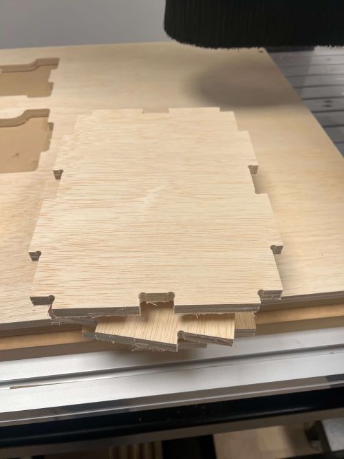
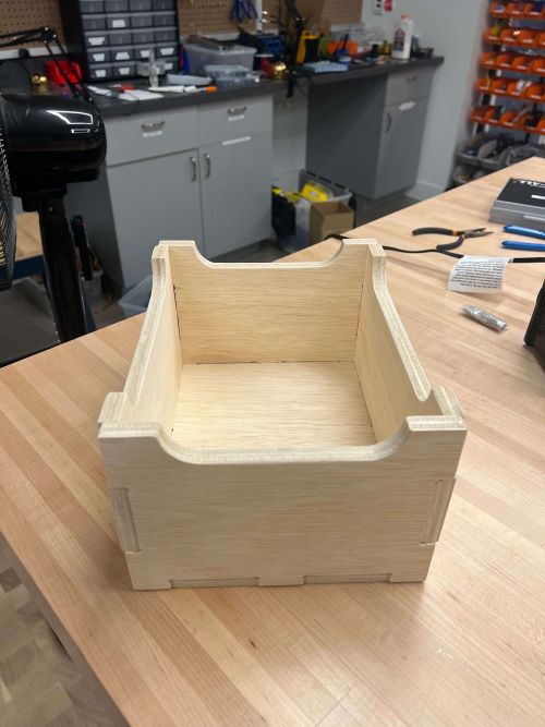
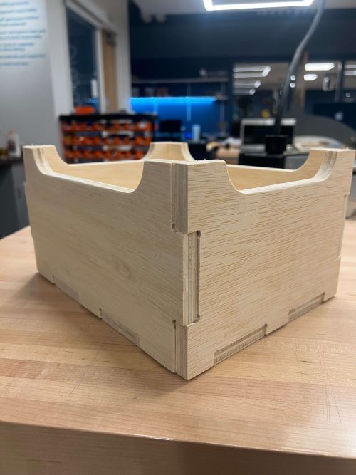
Sand areas that rewire a smoother finish and finally assemble the pieces!
Assemble the final sanded pieces and you're DONE!
Final Product