6. Electronics Design
For this week's group assignment, we learned how to use multimeters and an oscilloscope to measure electrical currents. We then used the test equipment in the lab to view the operation of a microcontroller circuit board.
We listened to a small lecture on how to use the oscilloscopes in our Fab Lab. When you attach one side to the signal and one to the ground, waveforms appear on the screen.
More in Depth Steps
Start with a standard blink sketch.
Attach the probe’s ground clip to the circuit’s ground.
Touch the probe tip to the part of the circuit board you want to measure.
Adjust the time and voltage scales and adjust until the waveform seems centered.
Start with the vertical scale set to 1V/division, and the horizontal to 0.5 sec/division. This will appear as a trace moving slowly across the screen at human eye speed.
Next, modify the simple blink sketch to have a shorter delay.
Adjust the horizontal scale for the new pulse frequency and adjust the vertical scale.
We then discussed the scale of the grid lines and how to quantitatively read them and adjust the trigger level so the waveform is stable.
Research
Prior to this week, I had no knowledge on anything circuit board related. Because of this, the in class lesson was a tool I needed to make sure to use.
Circuit Board: A printed circuit board (PCB) is a flat board that holds and connects electronic components using thin copper traces that are milled, instead of wires. The milled copper allows for electricity to flow between the components. The components may include resistors, capacitors, and microchips.
In Class
In class, we first had to download KiCad and install the Fab Electronics Library for KiCad to access the electronics that are more likely kept in Fab Labs.
Fab Electronics Library

Basic Circuit Board
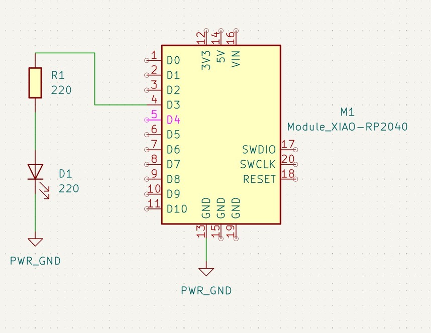
In our local lab session, we discussed simple circuits that just consist of a XIAO RP2040, an LED, and a resistor.
Using the schematic editor, we put together our class board.
Class Board
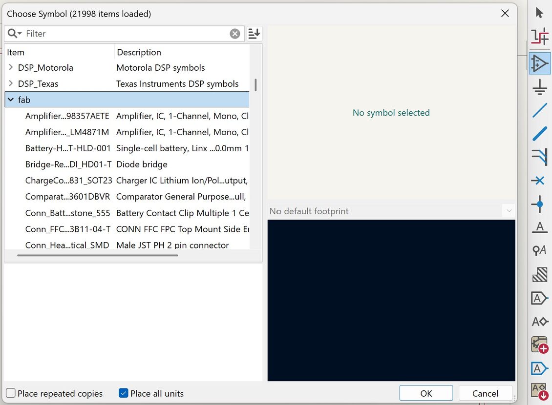
In the right column of the Schematic Editor, go to the triangular simple with a plus and minus sign in it. You then can see all the components, and since we installed the Fab Electronics Library, we can view the electronic components available in most fab labs.
Making Circuit Board
Start by adding a microcontroller using the directions stated above.
Next, add in the LED in the same way the microcontroller was added. It is called LED 1206 in the Fab Electronics Library.
Next, add the resistor and change the number of OHMS to 220. This is because the LED we added has a voltage of 220 and needs a resistor that can handle that voltage.
Then add two grounds. One connected to the microcontroller’s ground, and the other connected to the ground in the circuit.
Add wiring to combine all the components.
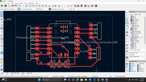
Change to update the PCB editor which allows you to format the board by adding routes that will be milled into the copper board.
Advanced Circuit Board
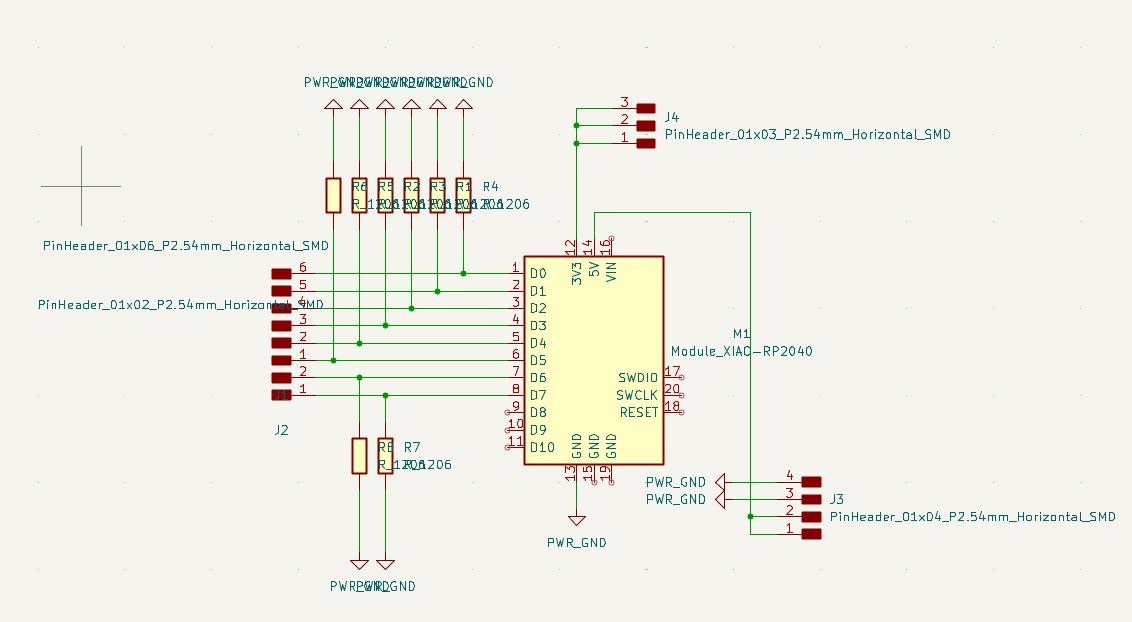
For my circuit board, I designed a custom PCB using a Seeed Studion XIAO microcontroller. I made sure to include many pin headers to connect things like sensors. I also ensured that I had pins for the TX, RX and Ground. This made the networking and communications week possible.
Schematic Editor
PCB Editor