4. Embedded Programming
This week, I followed a tutorial on using Wokwi for this weeks lesson. I then designed and programmed an embedded system in sofware, using Wokwi.
Week 4 GroupworkReasearch
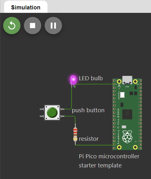
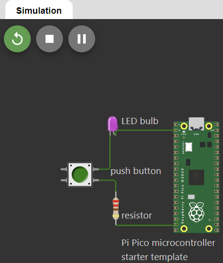
I designed a basic Rasberry Pi Pico circuit that uses a push button to control an LED. When the button is pressed, the circuit completes, allowing the current to go throught the resistor and LED, causing the light to go on.
Simulate Microcontroller's Operation


The positive leg of the LED is connected to a GPIO pin on the Rasberry Pico.
The negative leg is connected to the GND through the resistor.
One side of the push button is connected to another GPIO pin on the Pi Pico while the other side is connected to the GND.
The resistor limits the current going through the circuit, ensuring that the LED doesn't burn out from excessive current.
Write a Code for a Microcontroller
            void setup() {
                // put your setup code here, to run once:
                pinMode(0, OUTPUT);
              }


              void loop() {
                // put your main code here, to run repeatedly:
                digitalWrite(0,HIGH);
                delay(1000);
                digitalWrite(0,LOW);
                delay(1000);
              }
What each line does:
void setup() {
This starts the setip() function, which takes care of preliminary steps that must be done before the main code can run.
// put your setup code here, to run once:
A human-readable note that does not have any function.
pinMode(0, OUTPUT);
Puts the GPO pin into OUTPUT mode, so its sends out voltage rather than reading it in.
}
Ends the setup() function.
void loop() {
Starts the loop() function
digitalWrite(0,HIGH);
Sets the voltage on the GPO pin to High, which turns the LED on.
delay(1000);
Waits for 1000 milliseconds before doing the next step.
digitalWrite(0,LOW);
This sets the voltage on the GPO pin to LOW, which turns the LED off.
delay(1000);
Wait another 1000 millisonds
}
Finishes the loop function. Will go back to the start of the loop and continuously repeat.
  // the setup function runs once when you press reset or power the board
  void setup() {
    // initialize digital pin LED_BUILTIN as an output.
    pinMode(LED_BUILTIN, OUTPUT);
  }

  // the loop function runs over and over again forever
  void loop() {
    digitalWrite(LED_BUILTIN, HIGH);   // turn the LED on (HIGH is the voltage level)
    delay(1000);                       // wait for a second
    digitalWrite(LED_BUILTIN, LOW);    // turn the LED off by making the voltage LOW
    delay(1000);                       // wait for a second
  }