9. Input Devices
This week we did input devices, so I made a new circuit board so I could use a joystick to change the brightness of a LED
Circuit
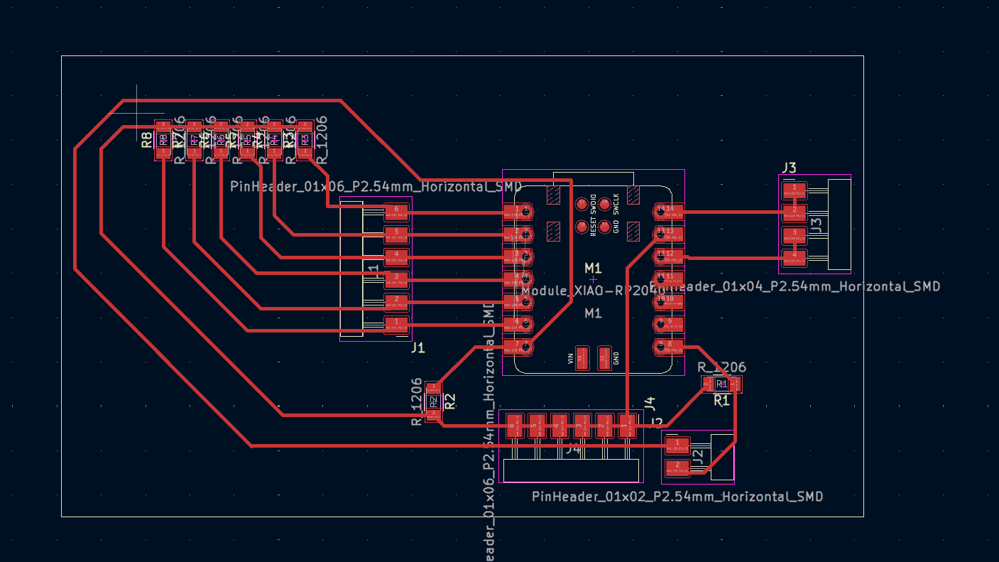
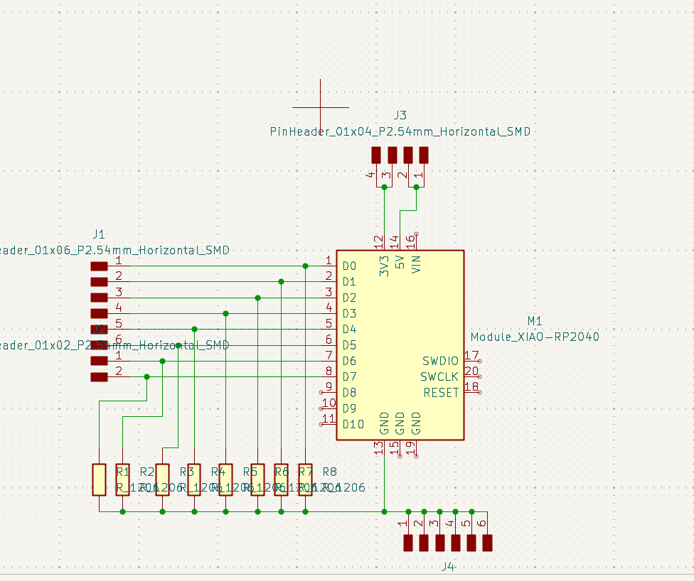
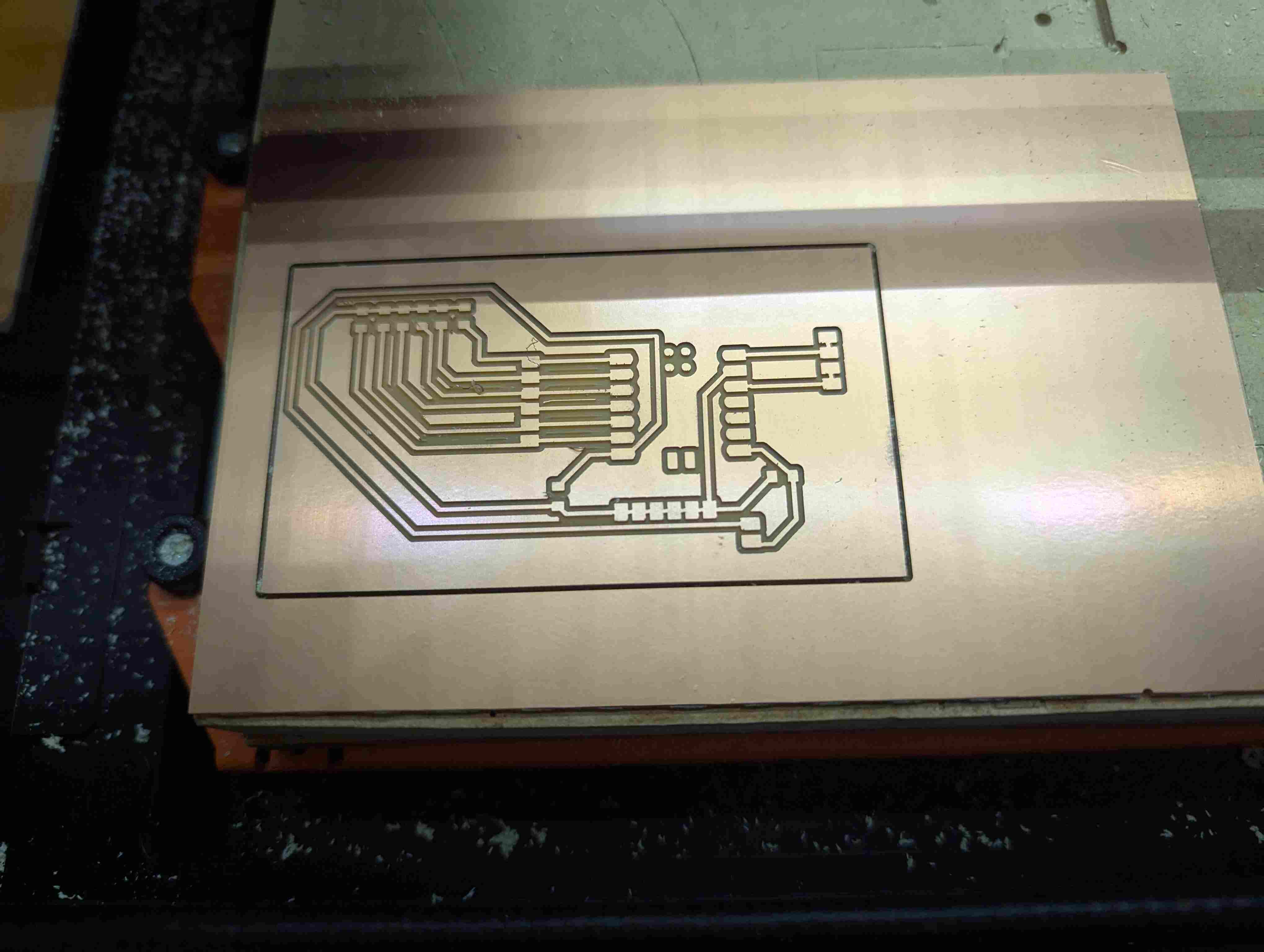
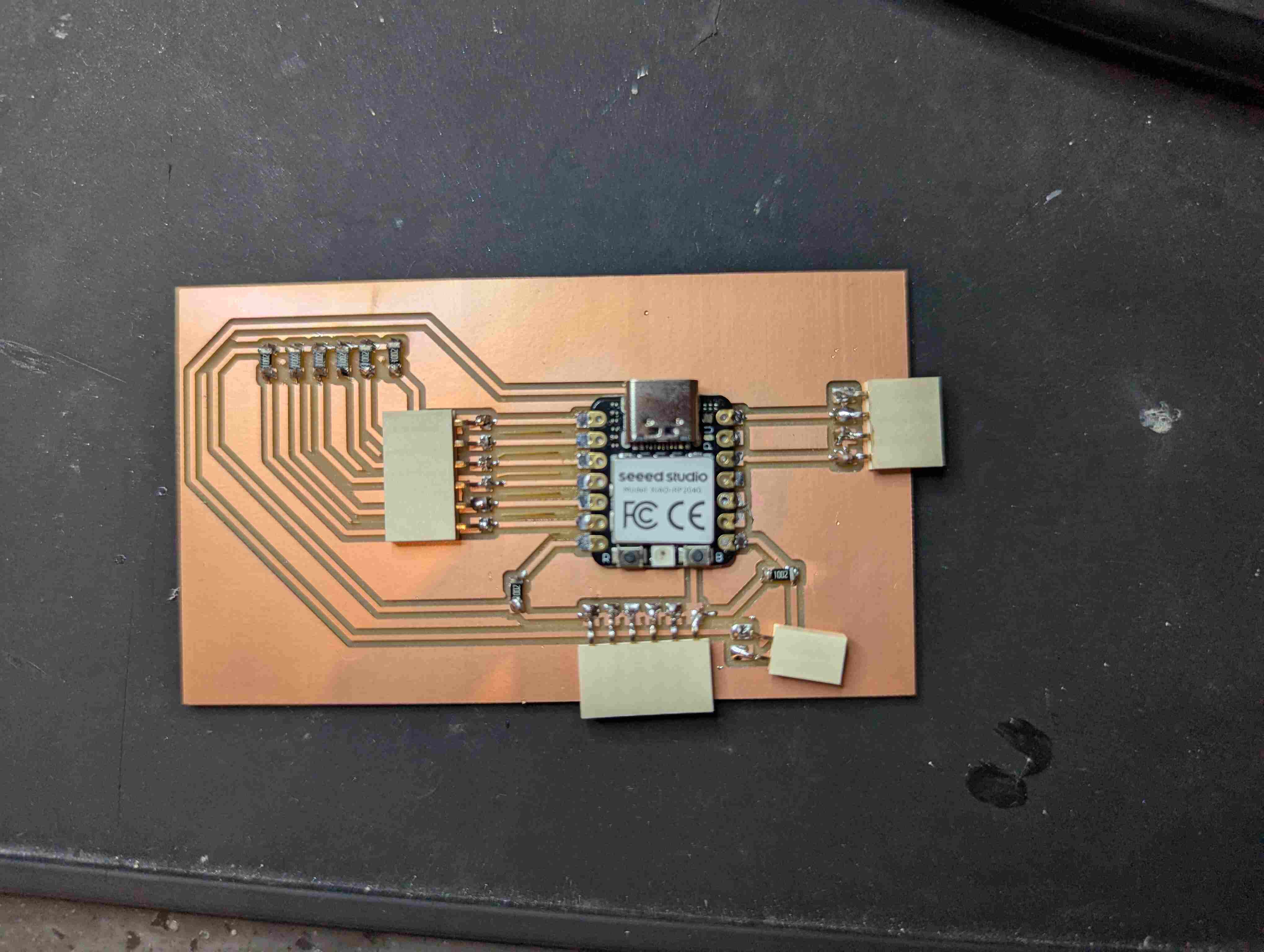
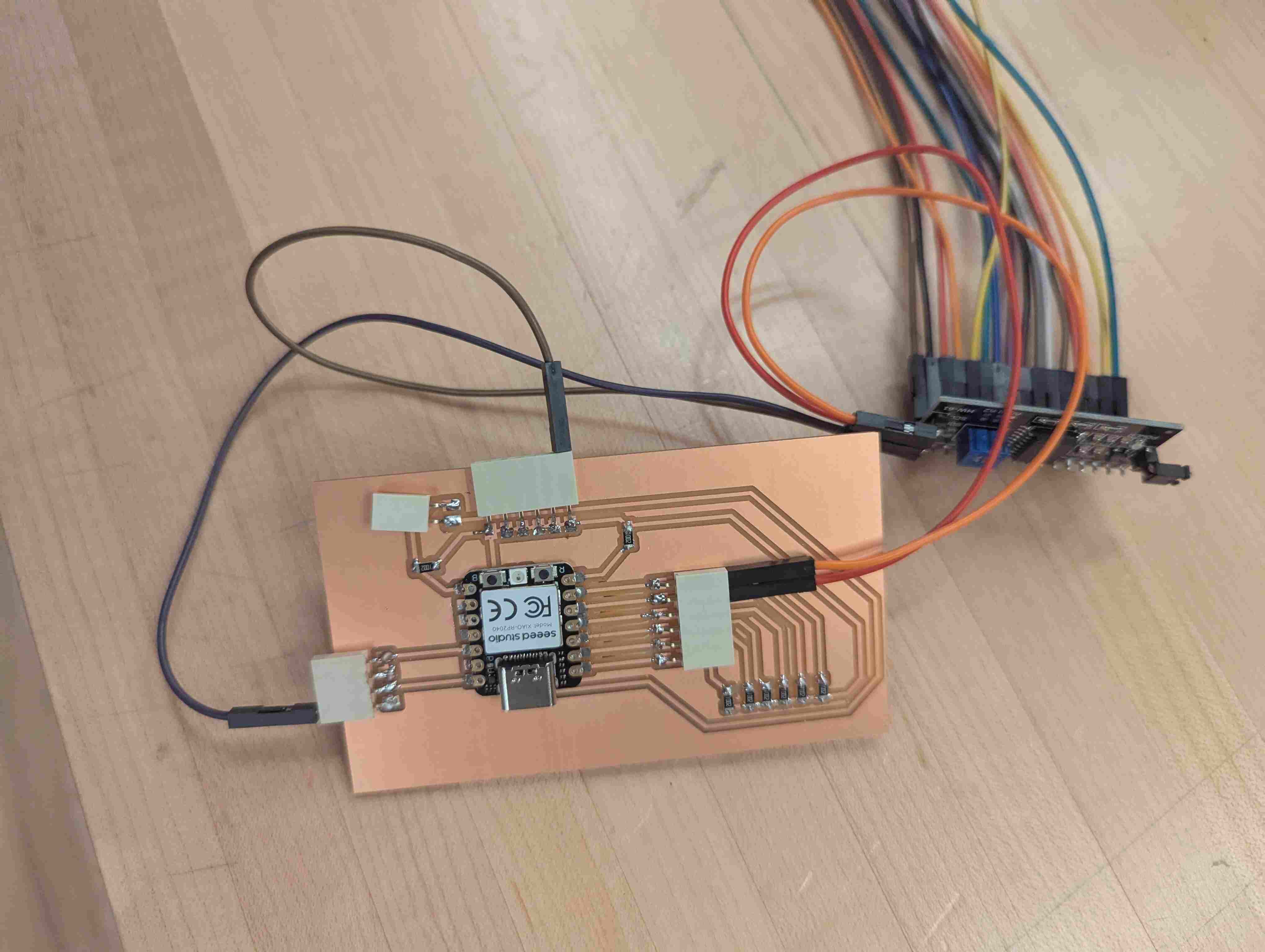
For this week, I made another circuit board that had alot of pins available so I can use it for different things in the future. I basically tried to make it more versatile by having a lot of pins available. The hard part was trying to figure out how to wire everything so it wouldn’t cross over each other. I did this by making connections under the microcontroller and making almost rainbow-shaped connections next to each other. I repeated the same things I did in week 8.
Putting Everything Together
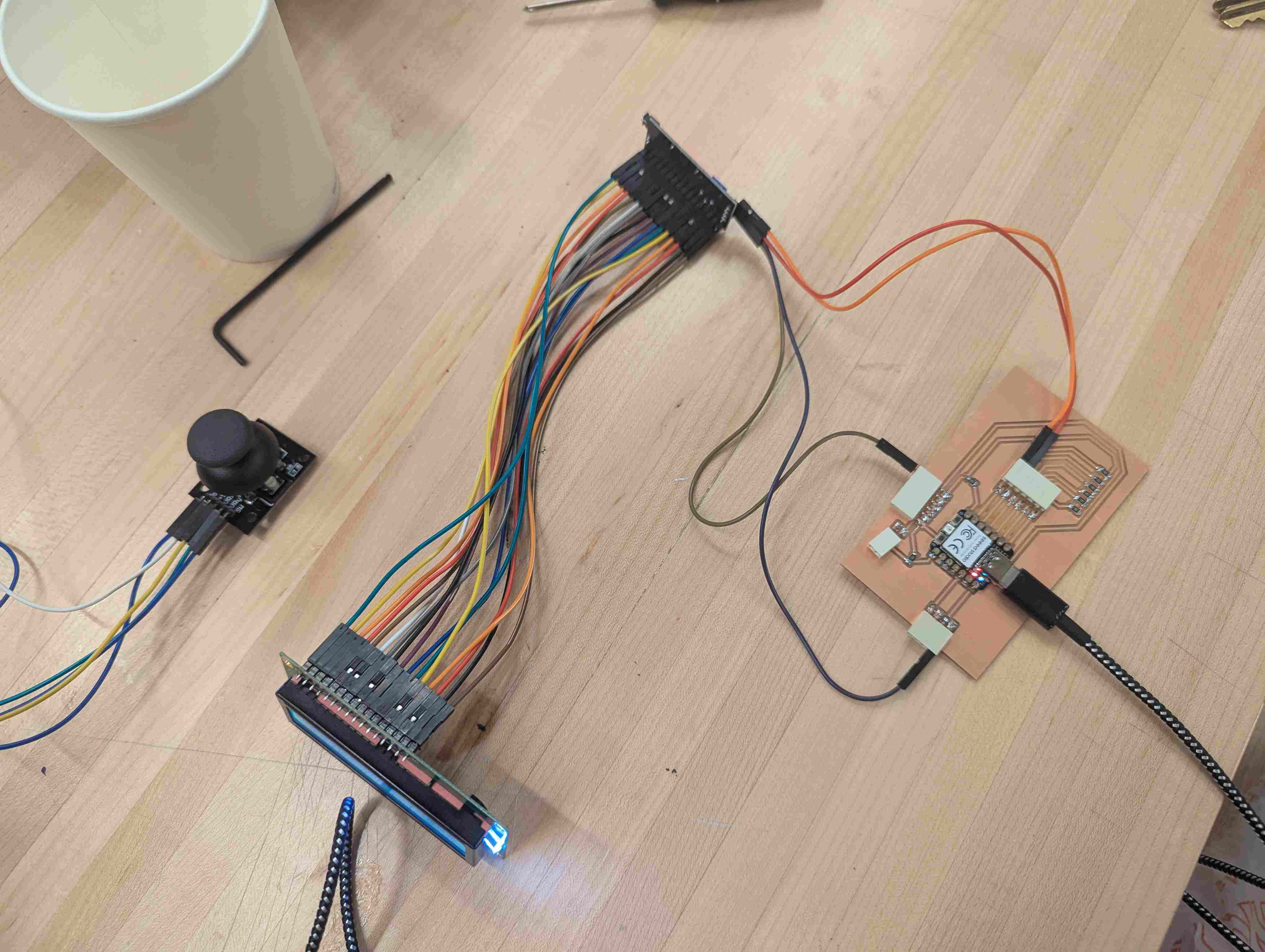
After my board was made, I got an LCD screen and a backpack for it. I used wires to connect the backpack to the LCD screen, and I connected the backpack to my circuit board. For the code, I looked at my peer’s documentation and changed the code to fit my needs. I put it into Arduino and had to download the LiquidCrystal_I2C library so I could use the code. When I first tried the code, my display screen wasn’t working, it just showed white square, so I used a different LCD with a backpack already soldered on it.
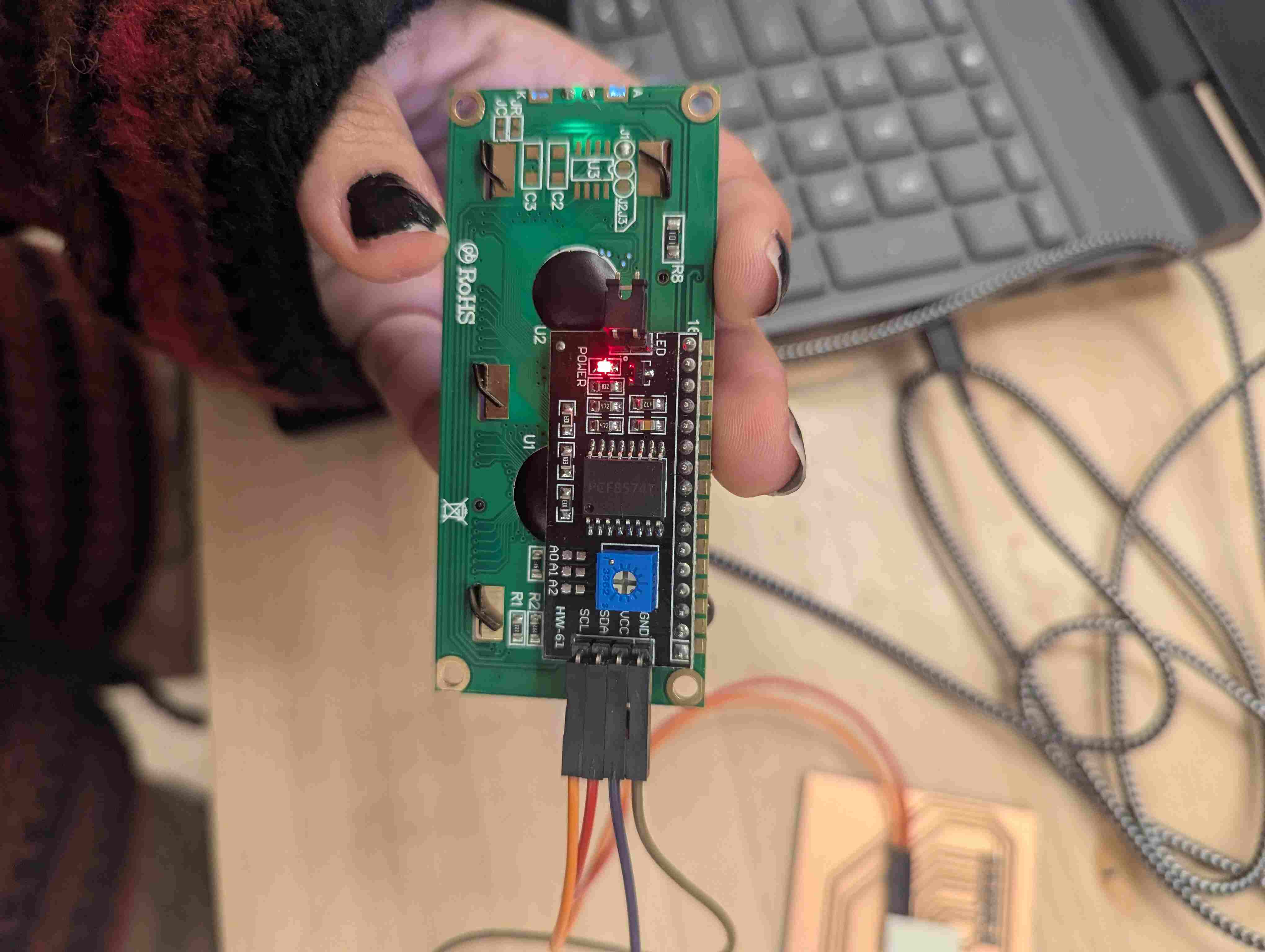
When I used the new LCD screen, it also wasn’t displaying the text, but on the back, you can use a screwdriver to change the brightness of the backlights on the display, so I did that until I could see the text.
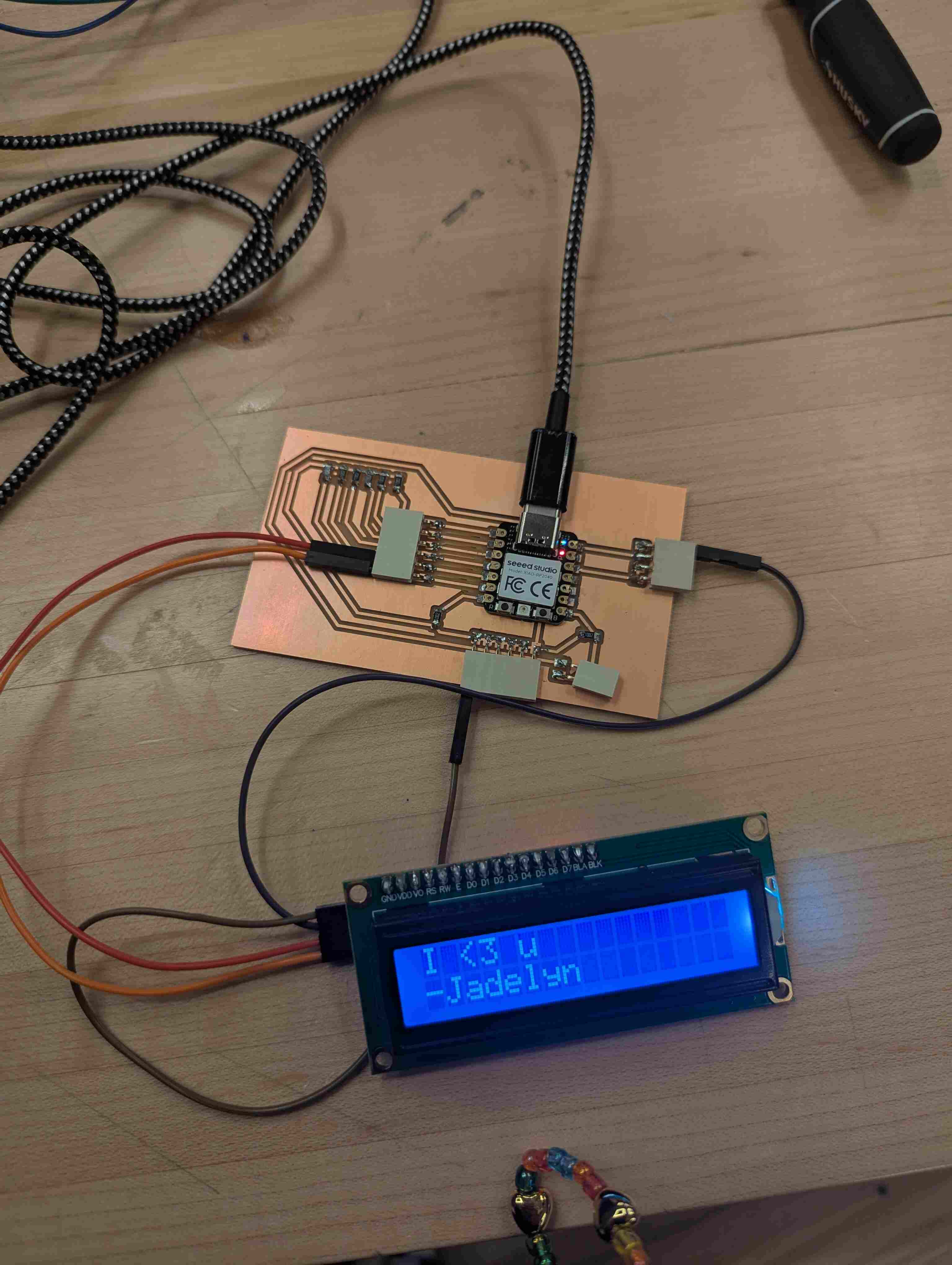
I wanted my screen to say “I <3 u - Jadelyn” so I changed the lines that controlled the words on the screen.
Groupwork
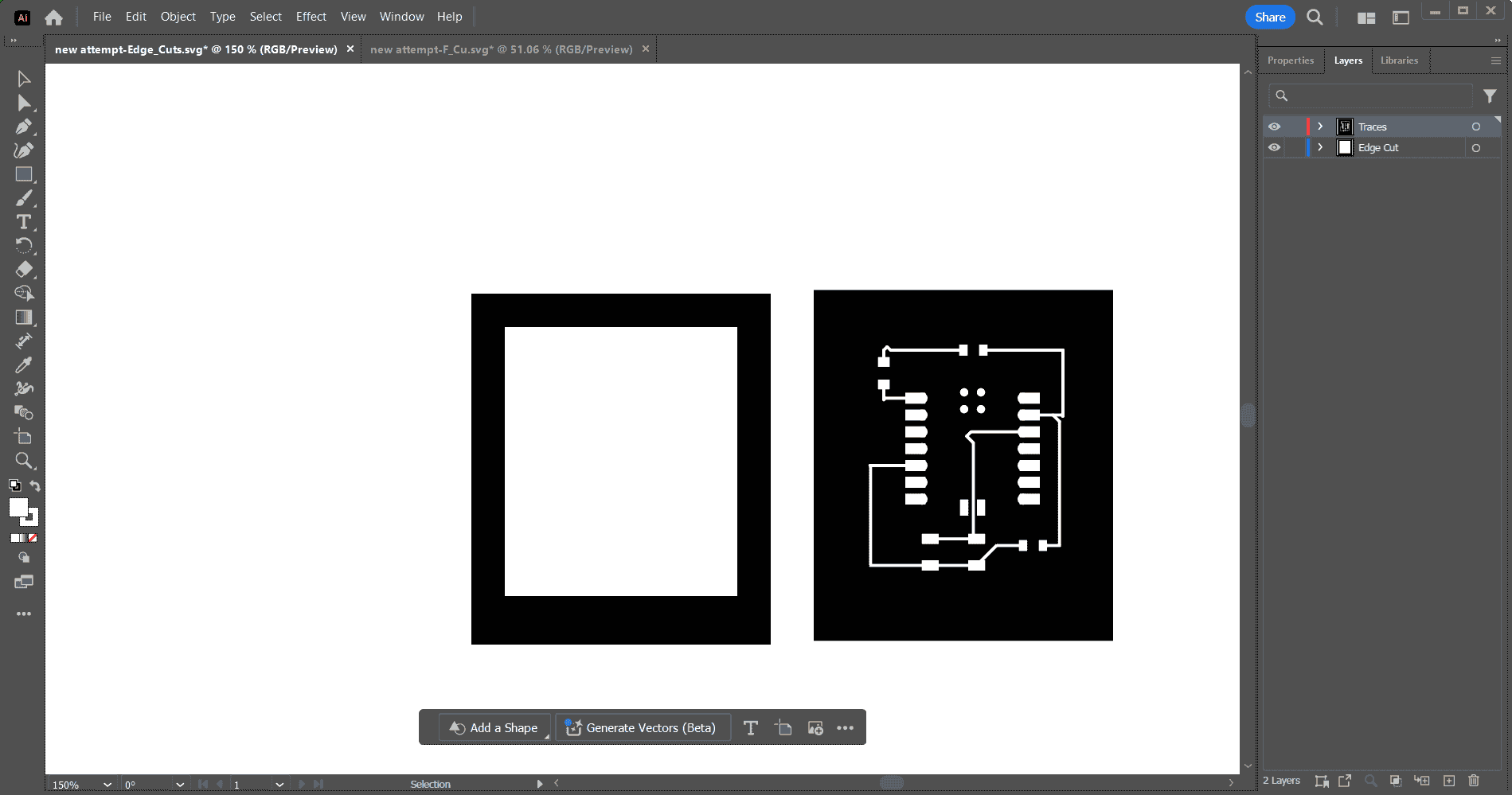
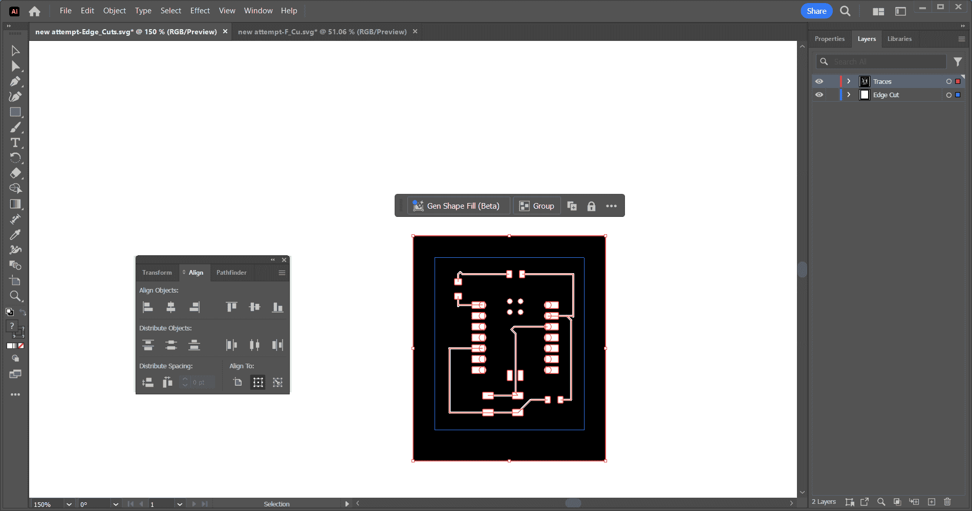
I opened the SVG files in Illustrator so they could get formatted correctly. I opened the edge cuts file and ungrouped everything and changed the inner part to white. Then I opened the F.Cu and grouped everything together and copied and pasted it into the same page as the edge cuts. Then I put the edge cut on a layer and F.Cu on a separate layer. Then I opened the align tool and selected both parts and then used the vertically align center tool and then the horizontal align center tool so that the F.Cu and edge were layered on top of each other. Then I hid the F.Cu layer and saved the Edge Cut layer as a PNG and set the ppi to 2400 and then repeated that for the F.Cu layer.
Useful links