8. Electronics production
This week I worked on learning about milling a circuit
Toolpath
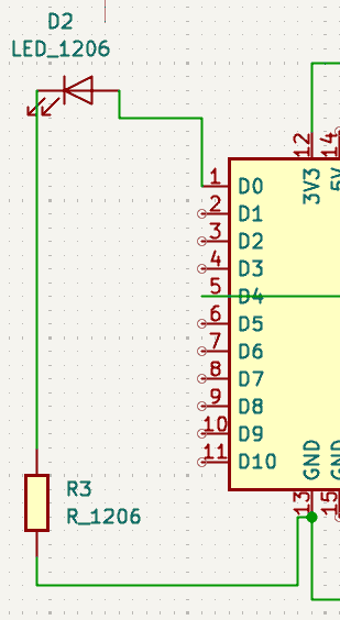
To create my circuit design I used KiCad, I opened the schematic view to grab the different parts I needed. I used the XIAO-RP2040 microcontroller, 2 resistors, a button (Switch_Tactile_Omron), and a LED. I placed the microcontroller in the center and the LED and one of the resistors on the left and used the wire tool (AKA highlight nets tool) to connect the LED to the D0 and the resistor. The resistor was connected to the LED and the GND pin.
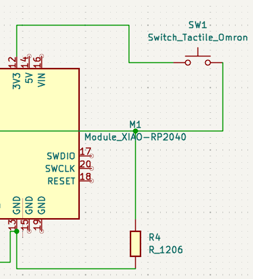
Next, I added a button and resistor to the right side of the microcontroller. I wired the button to the 3V3 pin and then to D4. Then I connected the resistor to the wire that is between the button and D4 so that it was also connected to D4, then I connected it to a GND pin
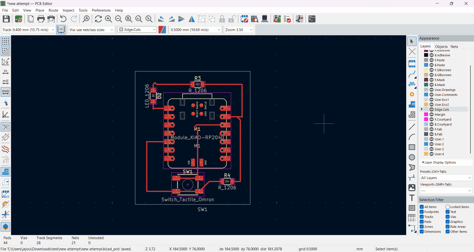
I opened the PCB editor and updated it so that it had the information from the schematic view. Once in the PCB editor, I moved the different components so that they could be wired correctly and compact. Each component had a blue line that shows where it is supposed to be connected so I just used the wire tool to connect everything and made sure nothing was overlapping. Then I went to the Edge Cut layer and used the shape tool to make a rectangle as the outline of my circuit board.
Exporting
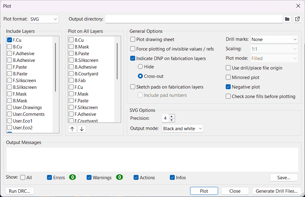
After finishing the board I had to get the files ready for the milling machine. I exported the files from Kicad by clicking file and then the plot button. This brings you a screen where you can select which layers you want to save. I clicked the F.Cu and Edge Cuts layer and made sure to change the format to SVG and to change it to negative plot. After changing the setting I clicked the plot button and it saved on my computer as SVG files.
Illustrator
I opened the SVG files in Illustrator so they could get formatted correctly. I opened the edge cuts file and ungrouped everything and changed the inner part to white. Then I opened the F.Cu and grouped everything together and copied and pasted it into the same page as the edge cuts. Then I put the edge cut on a layer and F.Cu on a separate layer. Then I opened the align tool and selected both parts and then used the vertically align center tool and then the horizontal align center tool so that the F.Cu and edge were layered on top of each other. Then I hid the F.Cu layer and saved the Edge Cut layer as a PNG and set the ppi to 2400 and then repeated that for the F.Cu layer.
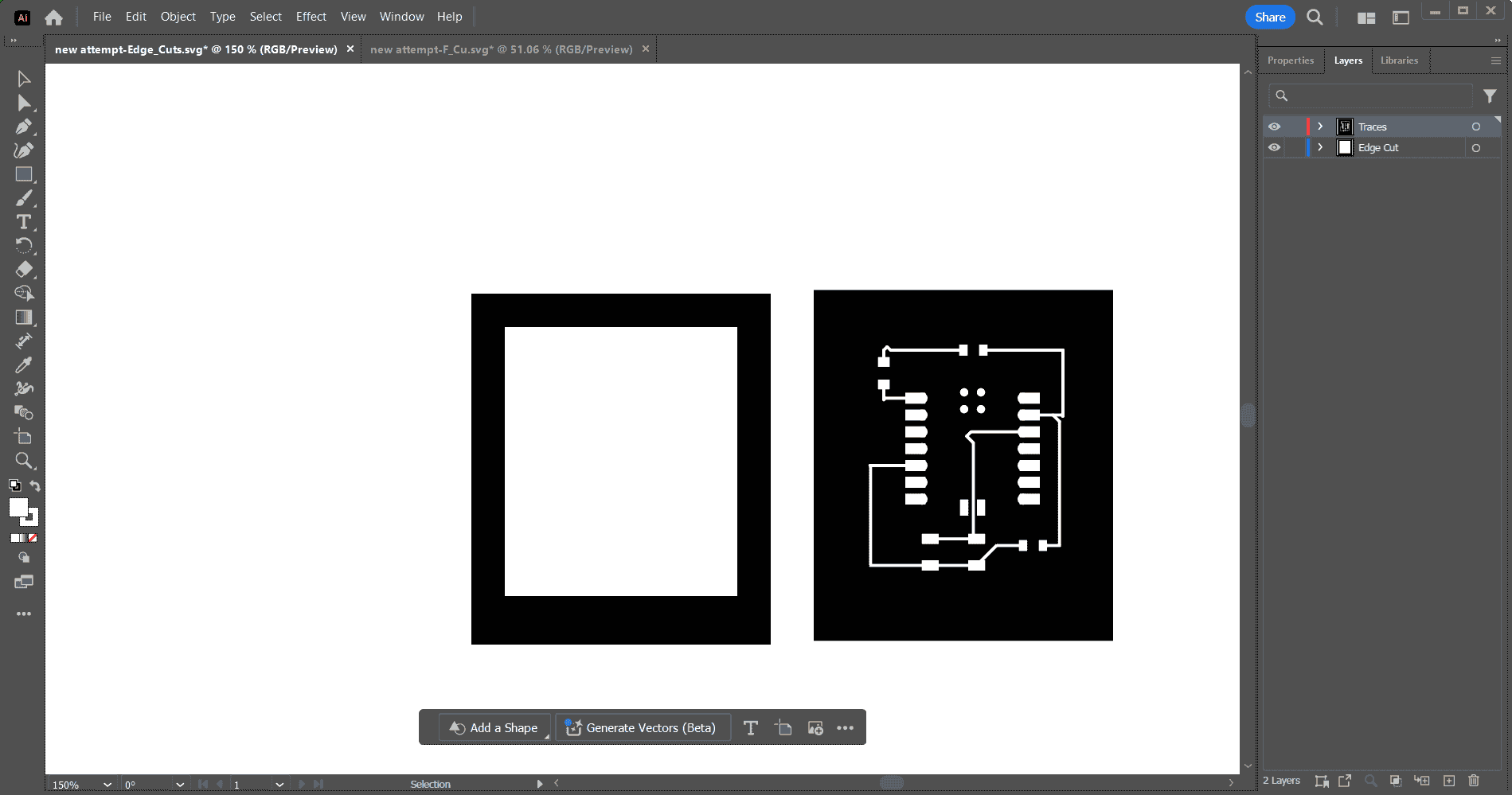
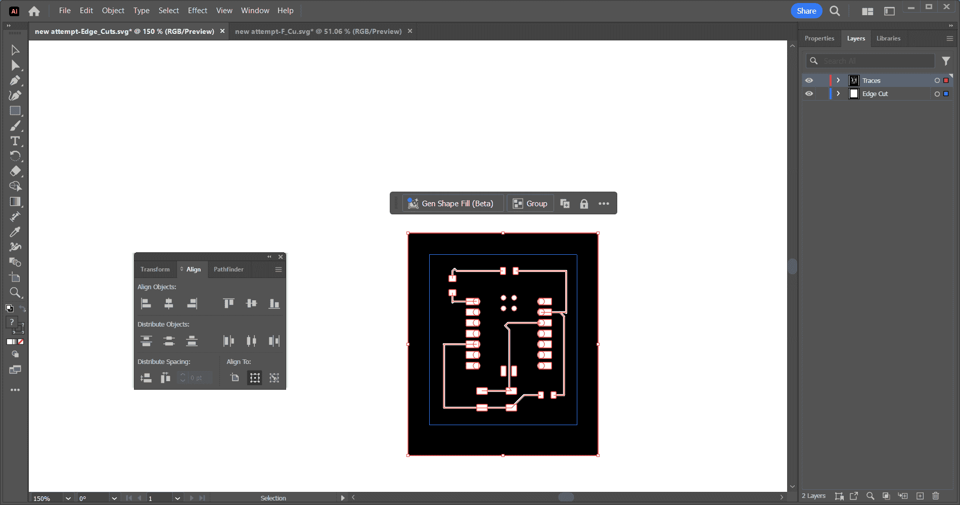
Modprojects website
After saving the files as PNG, I went to the modprojects website and right-clicked to open the menu. You then click programs, then open program then you scroll down to where it says Roland and under that you would click mill 2D PCB. Once you click this it opens up a new page where you have to change a few settings.
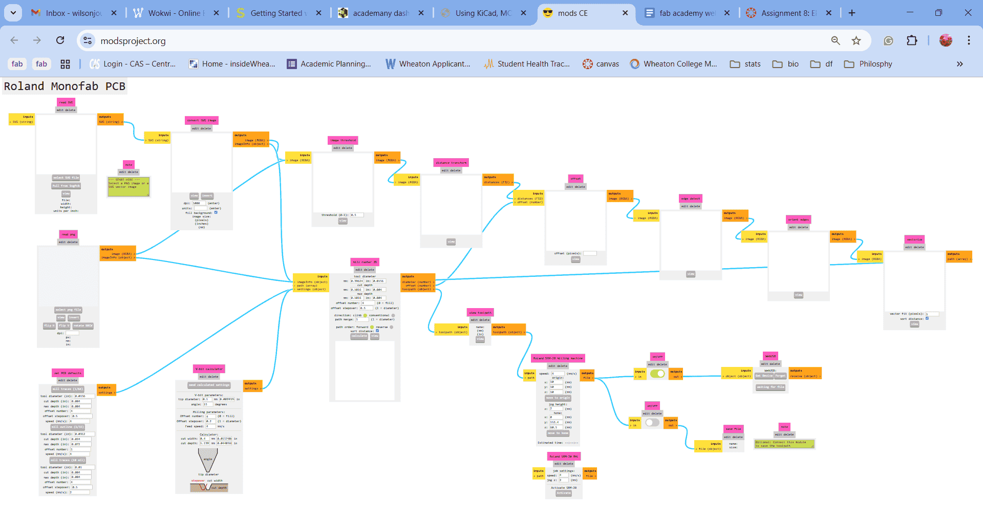
First, you import either an SVG or a PNG file, in my case, I imported a PNG. Next, you have to click whether you are milling the trace or the outline depending on which file you imported at the time. You are going to have to repeat all these steps for both the outline and trace.
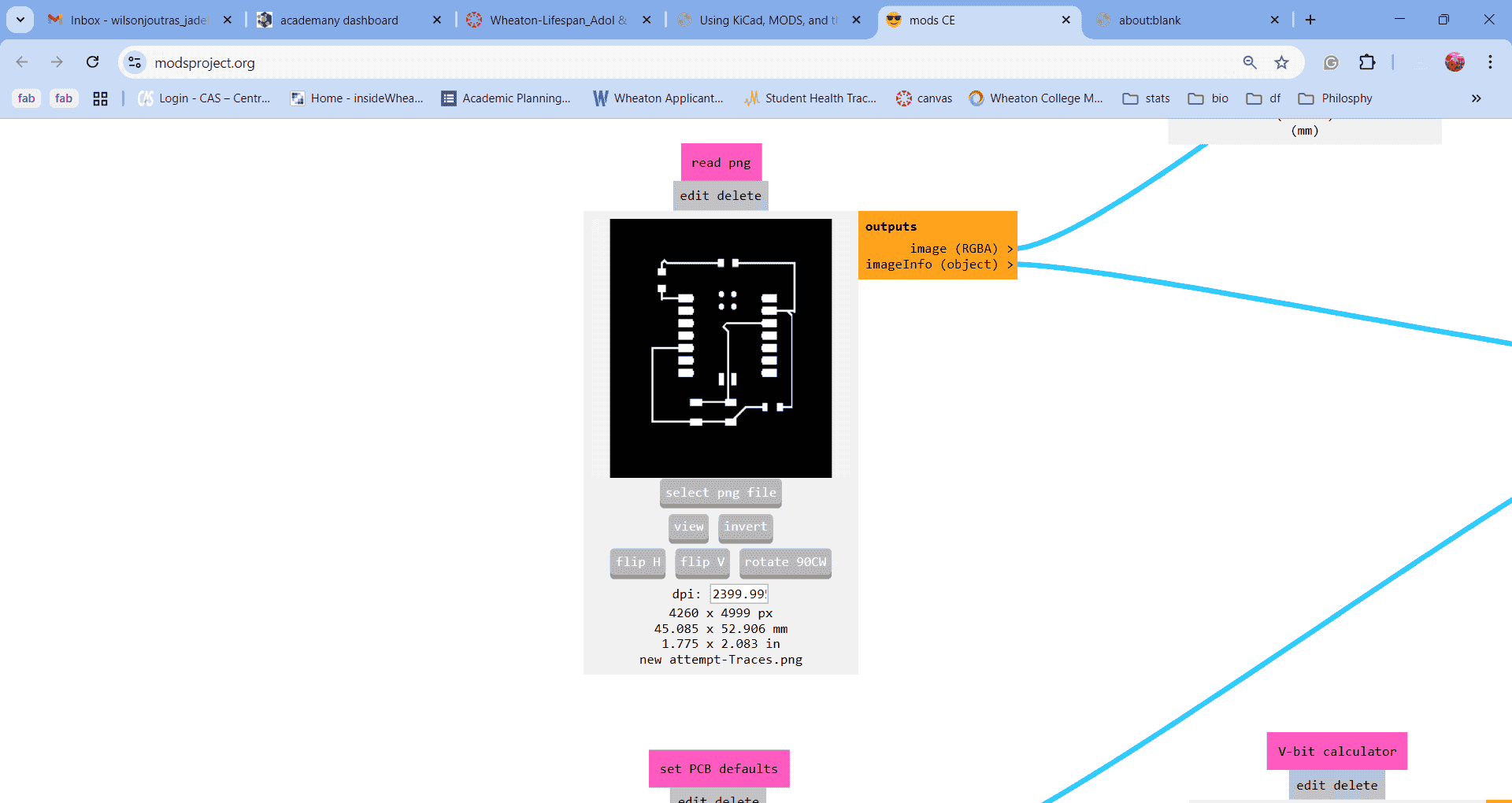
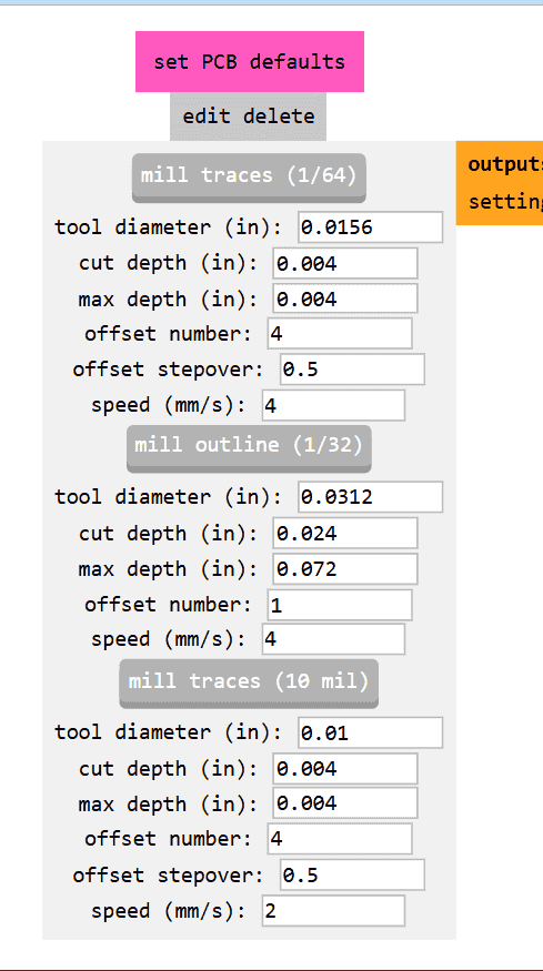
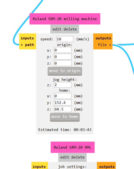
Then you have to change the speed and location for the milling so you set the speed to 10 and the X,Y, and Z to 0.
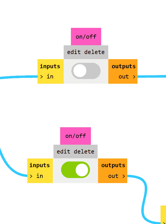
The on/off switch that leads to WebUSB is going to be on when you first look at it but you are going to turn it off and then the on/off switch that's below it that leads to save file, you are going to switch that one on.
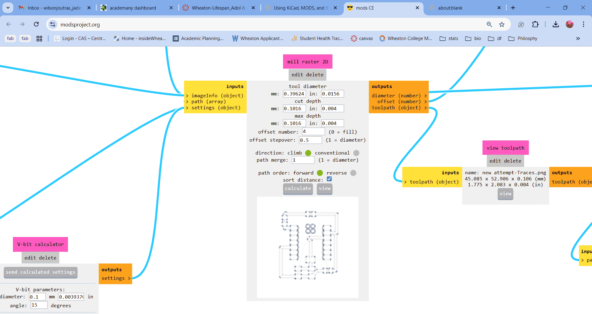
Finally, in the middle of the screen, there is a box that says calculate and you are going to click that and it should save an RML file and then it should open another page that shows you the outline of your circuit.
Milling
We made it off the computer stuff yay!! Now it's time to actually use the milling machine. I emailed myself the RML files so I could download them on the computer connected to the milling machine. I had to set up the machine so I took a copper sheet and put double-sided tape on the bottom and placed it in the bottom left corner of the sheet inside the machine. I also put the 0.4 mm end mill head in so I could cut the traces out first.
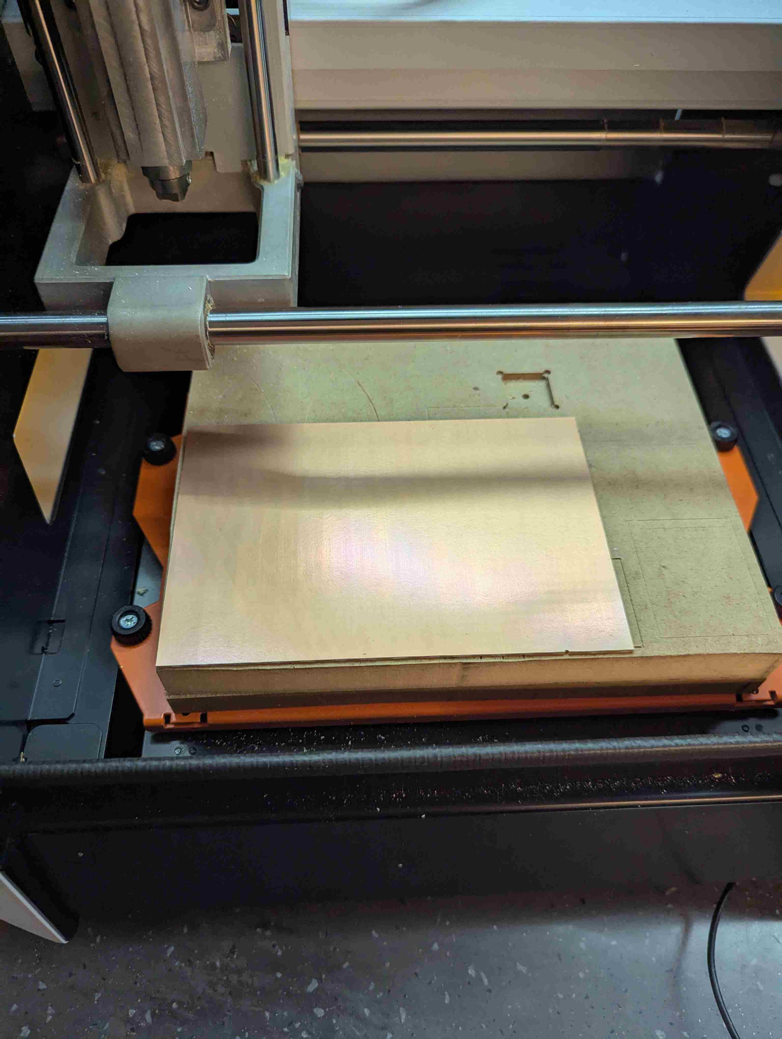
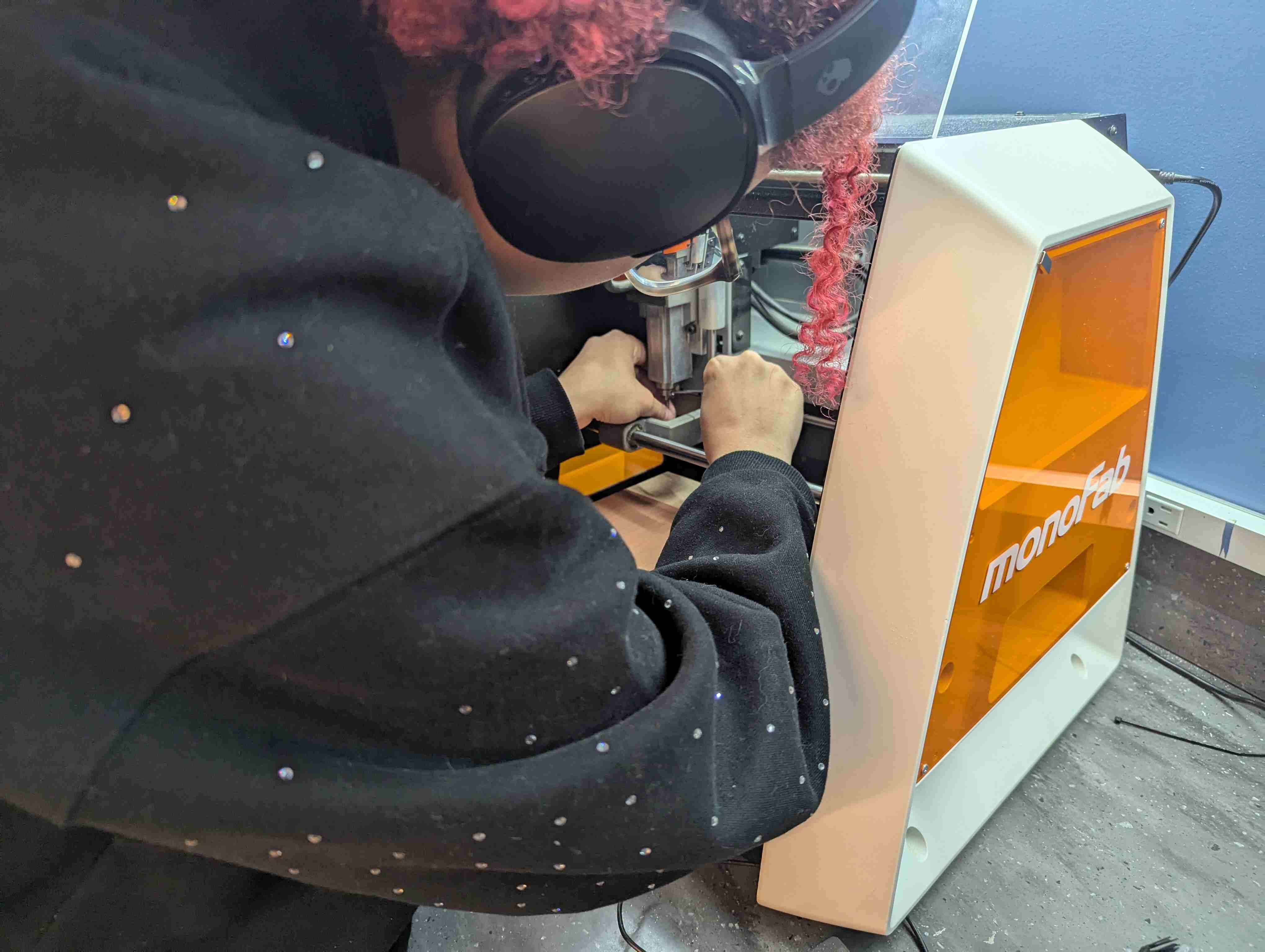
Next, you have to set the starting spot so you use VPanel to control where the milling head is, I brought it to the left front corner of the copper sheet. Then I click the x/y button to set that as the starting place. After this, I need to change the height of the head. I brought the head down by using the Z- button. After getting it pretty close to the copper sheet I loosened the head so it naturally fell onto the sheet and then I tightened it again and pressed the Z button to set this as the starting height. After I set it, I brought the height up by about 2 mm so that the head could move freely.
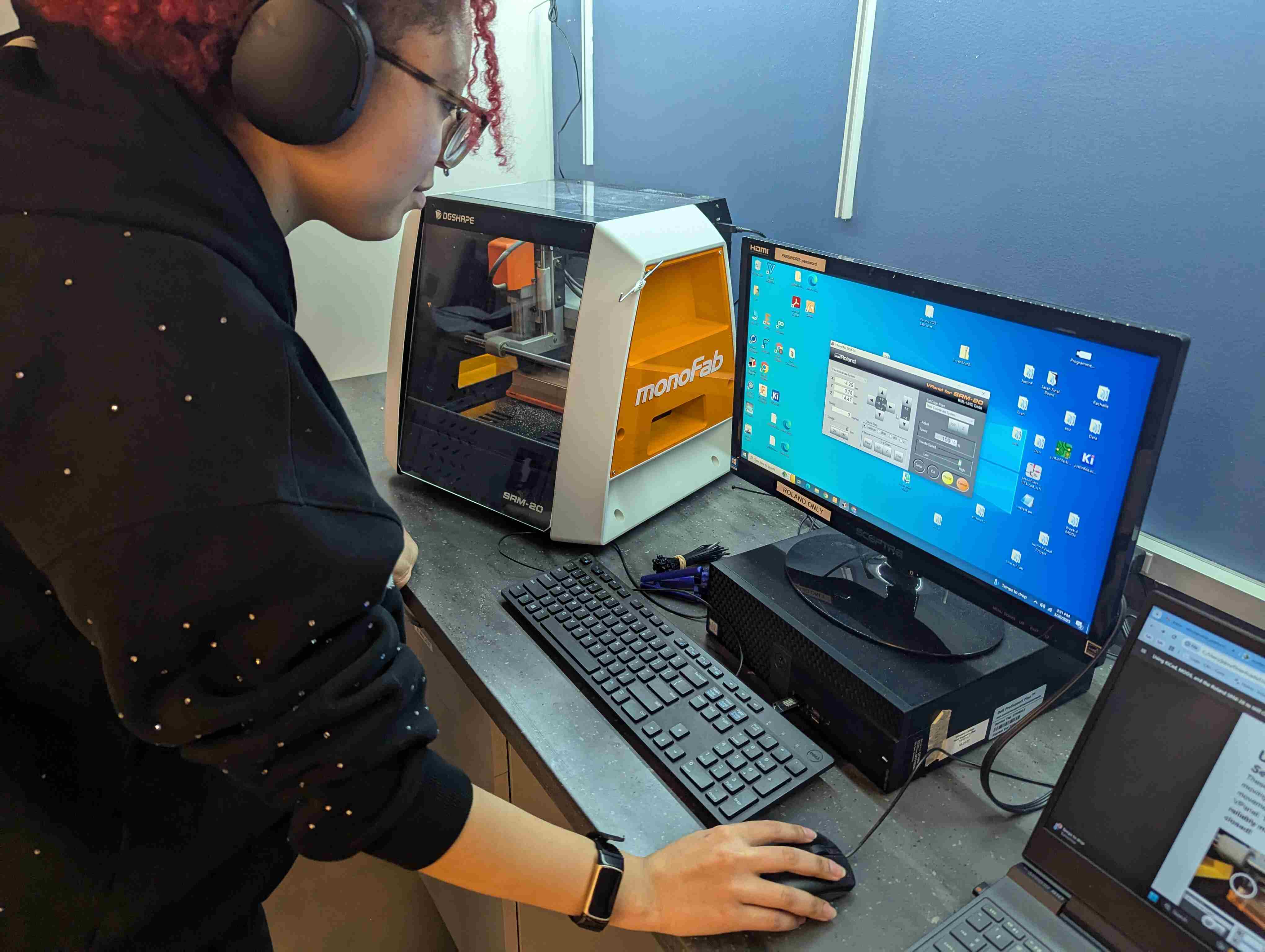
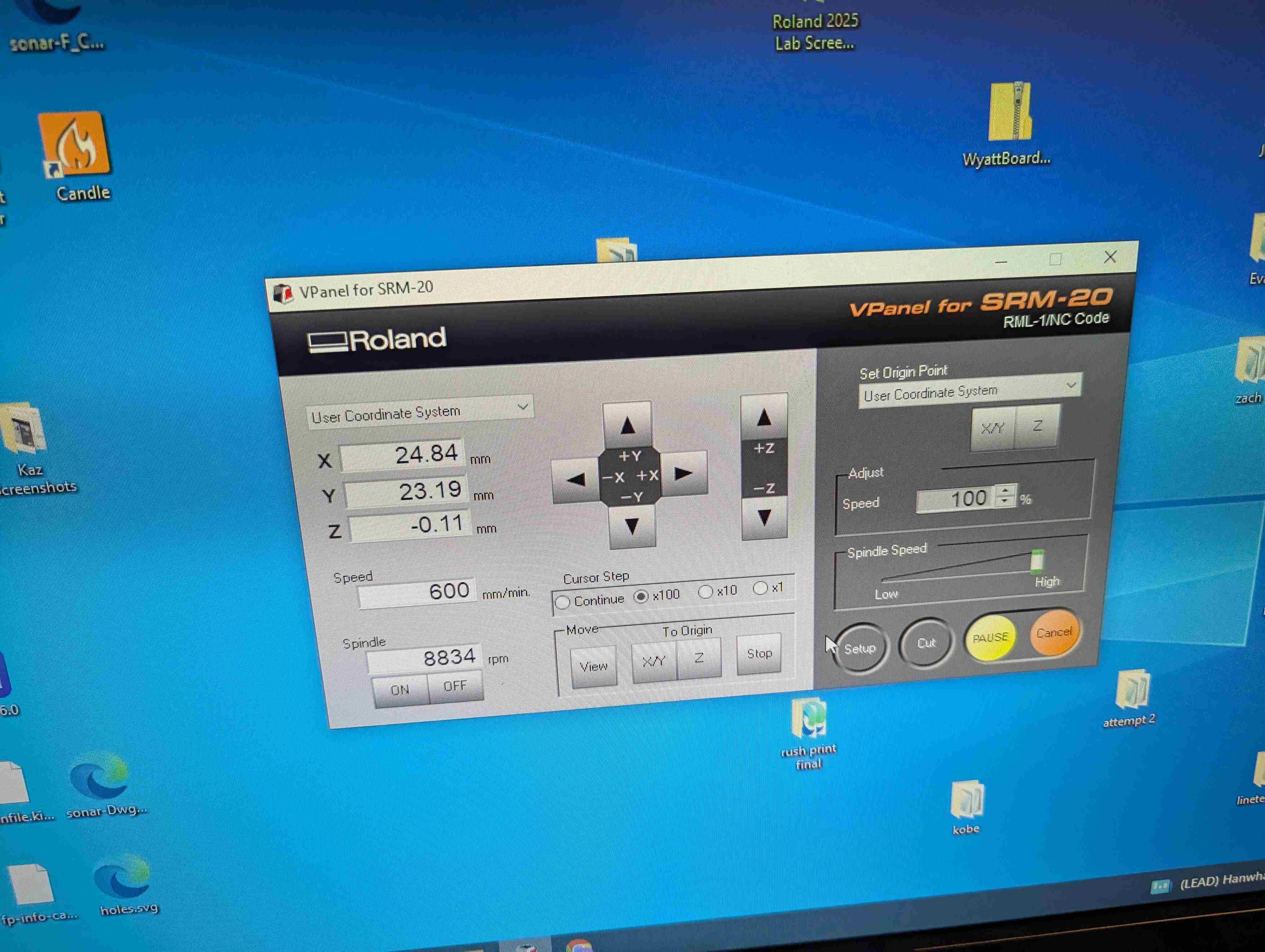
Once everything was set I pressed the cut button and uploaded my traces file. After I press the output button to start the actually milling process.
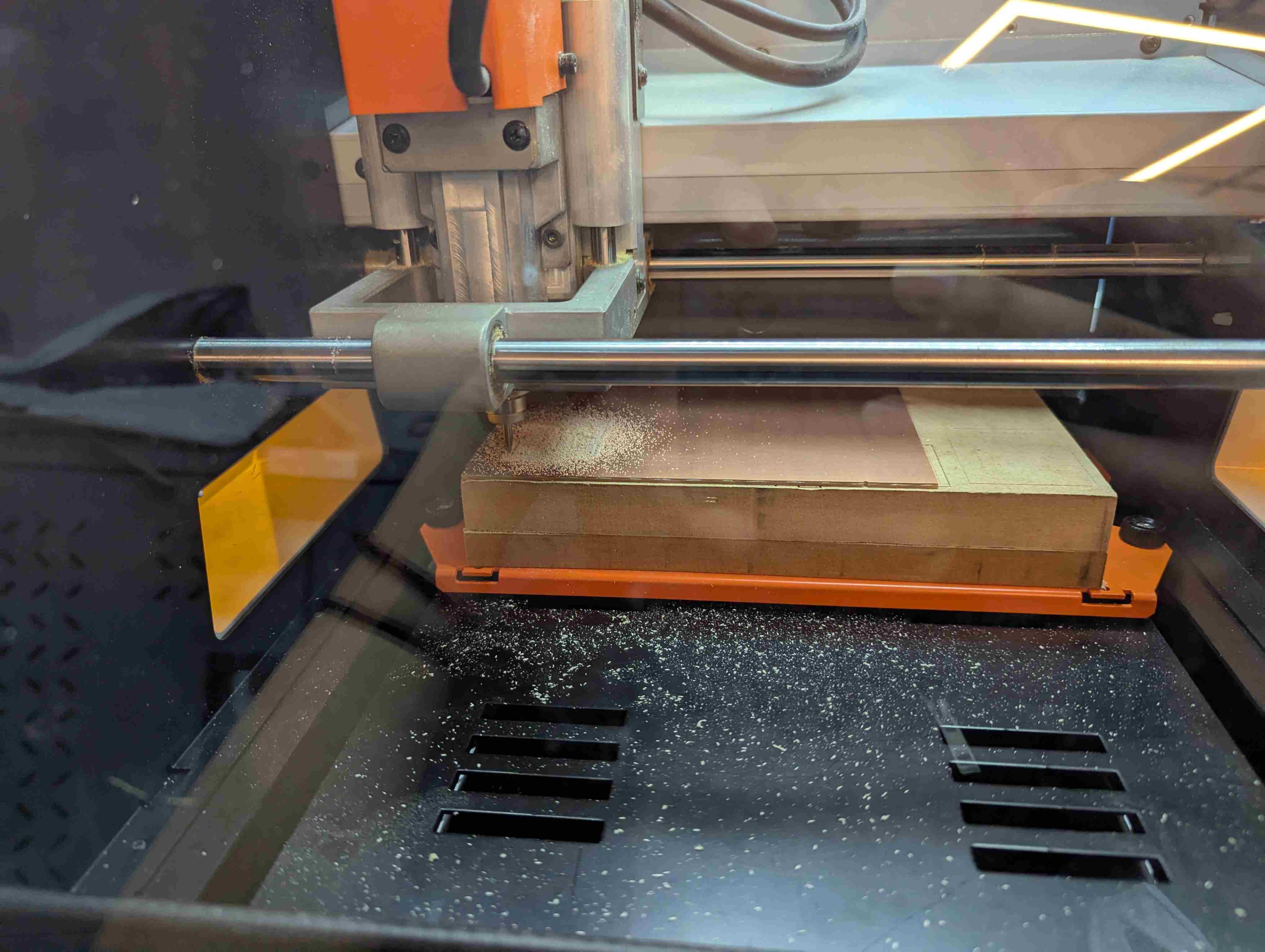
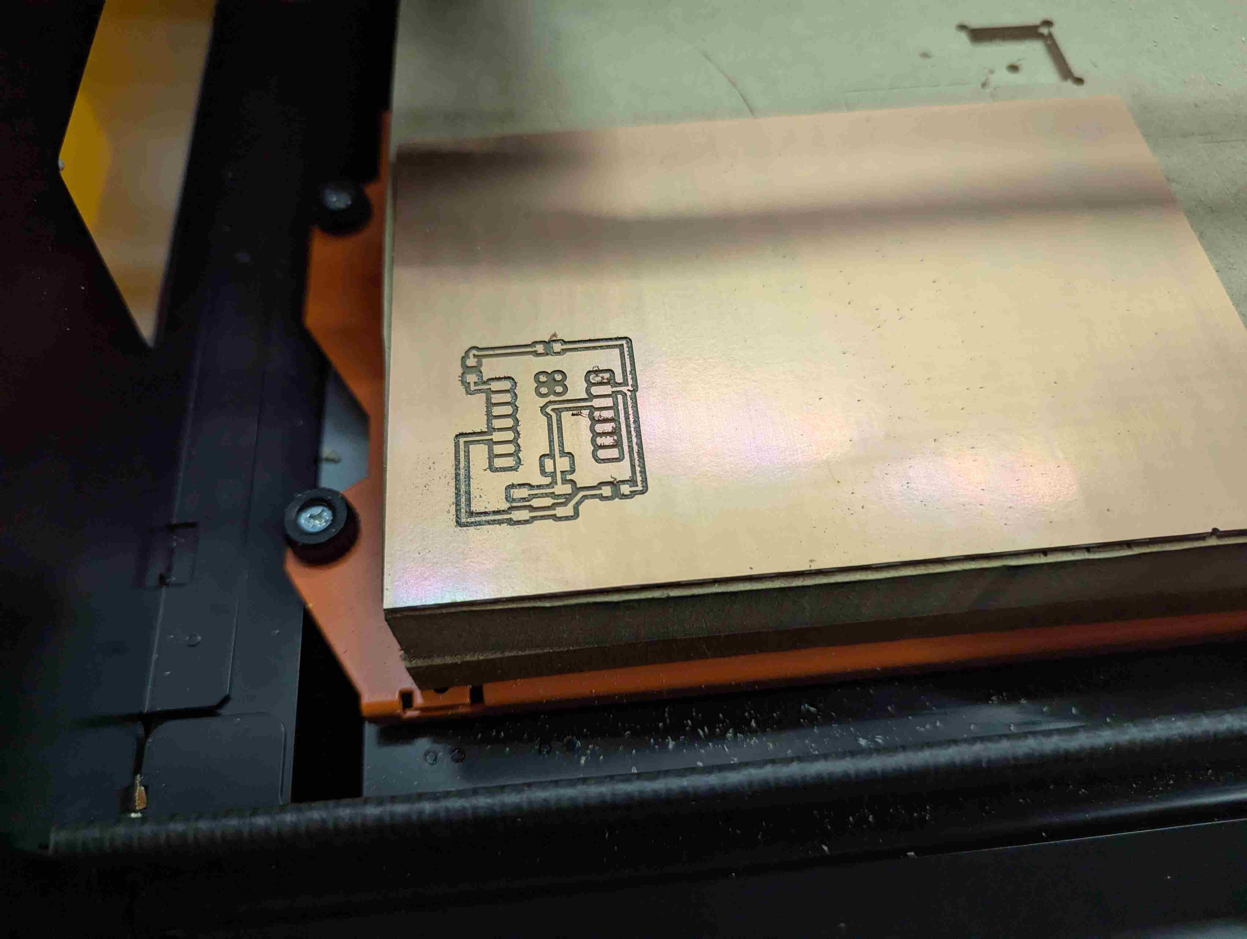
After the traces were done, I vacuumed the dust up and changed the milling head to the 0.8mm head for cutting the outline. Then I pressed the x/y button that's under bring to origin so that it's back to the starting spot. Then you have to repeat the steps for setting the height. Then you upload your outline file and start that cutting session.
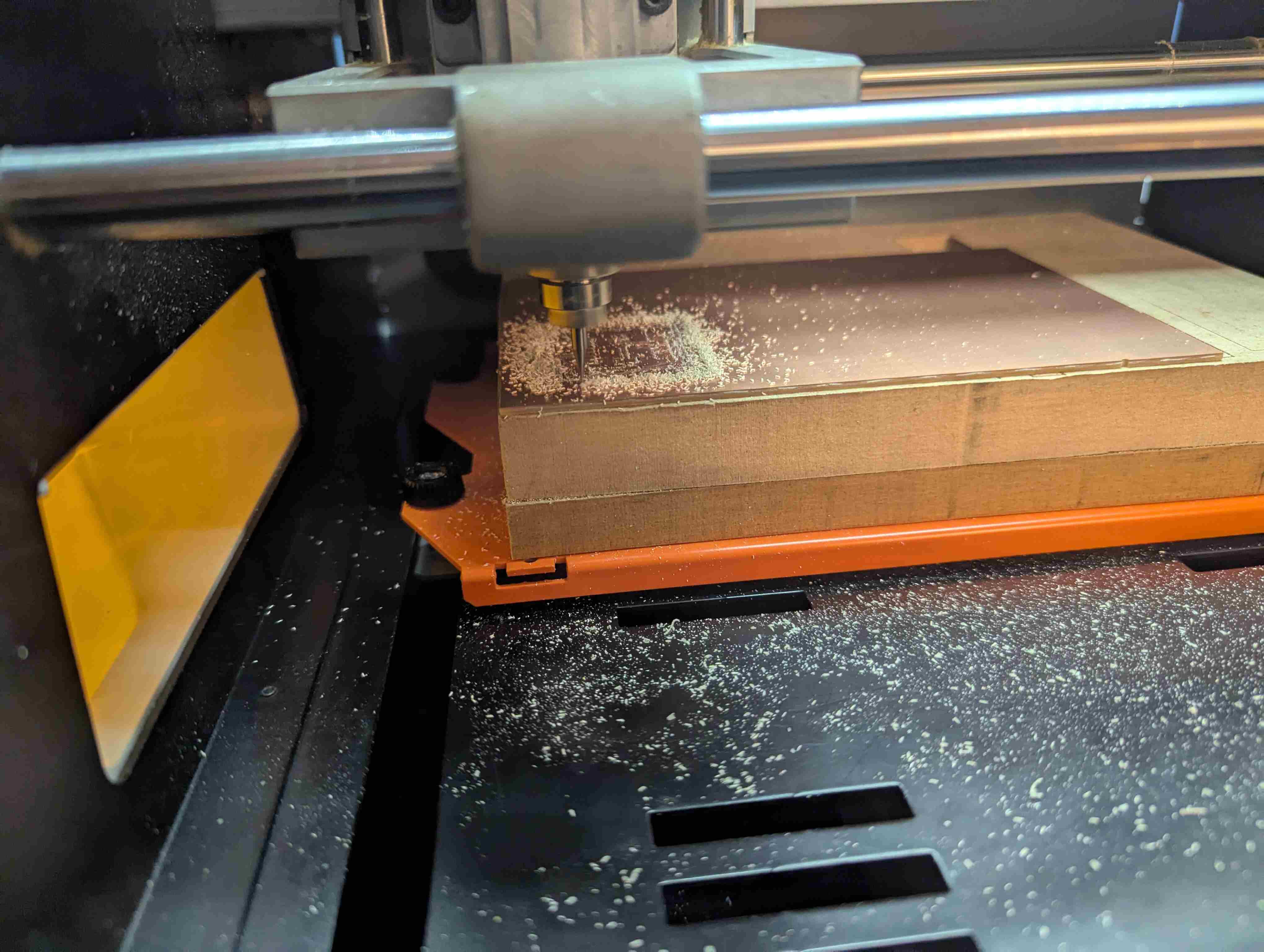
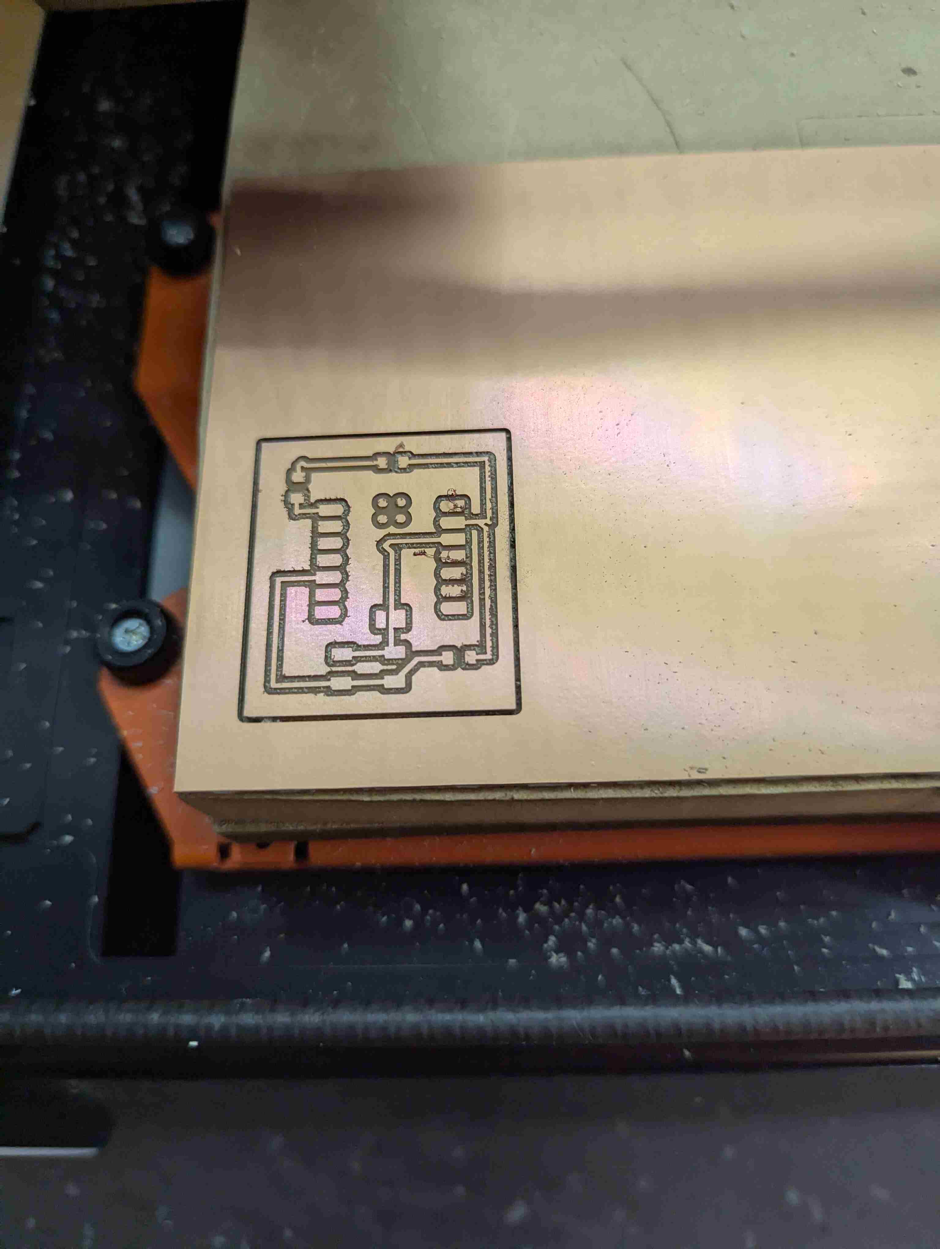
After that was finished I took the board out of the machine and started the soldering process.
Soldering
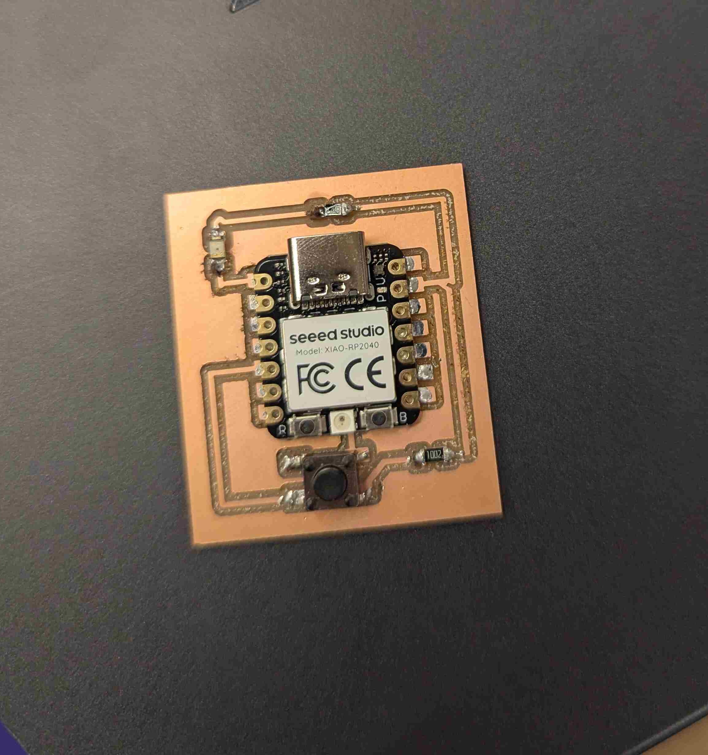
I took my board and grabbed the XIAO RP2040 microcontroller, 2 resistors, and an orange LED. I soldered on the microcontroller first. Then I added a 2200 resistor that is closest to the LED. Then I used a 1002 resistor near the button. Then I soldered the LED and finally the button.
Testing and revisions
I tried to test the circuit but I made one fatal error. I placed one of the resistors in front of where you are supposed to plug in the microcontroller so I couldn't even use it. So I went back to the start and slightly moved the resistor to the right so it was out of the way but still connected to everything. Then I repeated everything I just talked about.
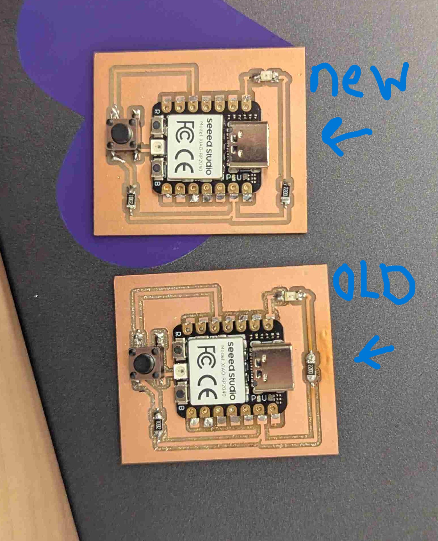
Now I have a finished circuit that I can test. I went to Arduino and took my code from my embedded programming week since that was what my circuit was based on. I had to download the right microcontroller from online so I could test it, I will link it below. Then I changed the pins to the right ones and uploaded it to my circuit. It ended up working yay!! So when I held down my button the light would turn on and brighten each second and then turn off and repeat until I stopped holding down the button.
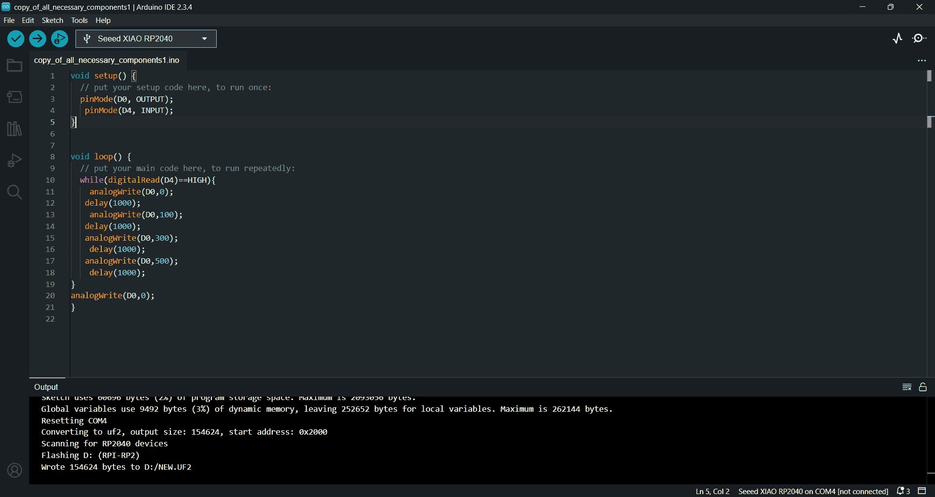
            void setup() {
                // put your setup code here, to run once:
                pinMode(D0, OUTPUT);
                 pinMode(D4, INPUT);
              }


              void loop() {
                // put your main code here, to run repeatedly:
                while(digitalRead(D4)==HIGH){
                  analogWrite(D0,0);
                 delay(1000);
                  analogWrite(D0,100);
                 delay(1000);
                 analogWrite(D0,300);
                  delay(1000);
                 analogWrite(D0,500);
                  delay(1000);
              }
              analogWrite(D0,0);
              }
Useful links
- Group Project Documentation
- Mod Project
- Arduino microcontroller download
- kicad schematic
- kicad project
- kicad PCB