4. Embedded programming
This week I worked on learning about programming and circuts
How it went
This week was interesting because I know absolutely nothing about programming so I had a hard time understanding everything. First I worked on my group project which you can check out by the link in helpful links. For my individual project, I was trying to figure out what to do and I decided on trying to figure out how to make the LED brightness change but I looked up how that worked and found it to be quite complicated. So I decided to figure out how to use the button, I watched a YouTube video for reference. I learned that the left pin of the LED has to be put into a GND and the other is plugged into power. Then I connected the button to the right pin and connected it to a resistor like you would if it was just the LED. Then you plug it back into the Raspberry Pi and it works.

Redo
I am redoing this week because my code didn’t really interact with my circuit. I ended up coming back to my first idea of impacting the LED brightness.
What I used
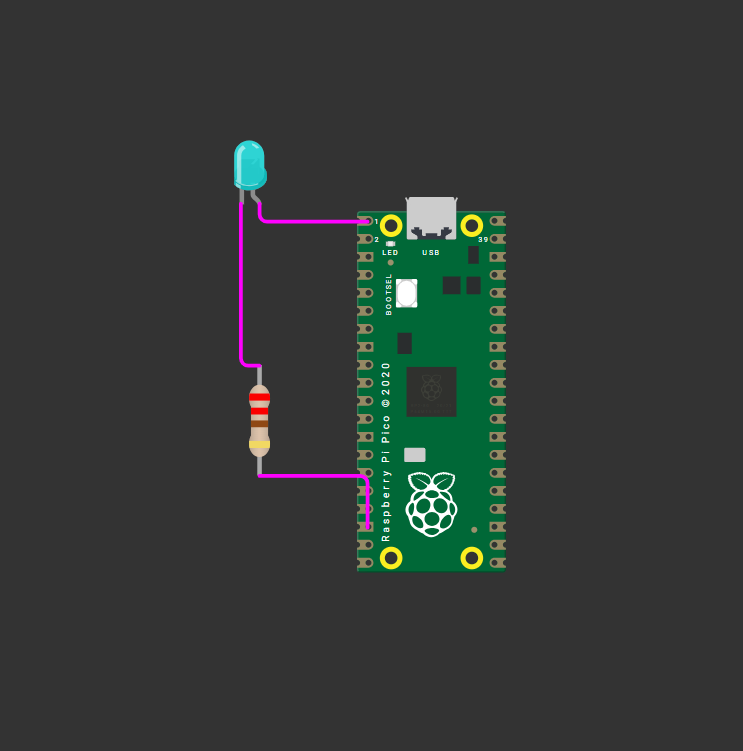
I used the Wokwi website to do this. I started off with just trying to change the LED’s brightness so I got an LED, resistor, and raspberry pie pico. I connected the right leg of the LED to GP0 and the left leg to the resistor. I connect the other side of the resistor to a GND pin.

coding for brightness
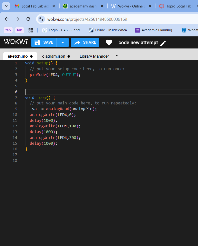
My professor gave me some help with what to use. I used AnalogWrite() in my code to choose the brightness of the LED. I watched a few YouTube videos to understand how it worked but I got my main information and reference from one specific video which I’ll link to. I made it so that each second the brightness increases and then it turns off. I did this by changing the value of brightness just slightly and then adding a delay.

coding for more
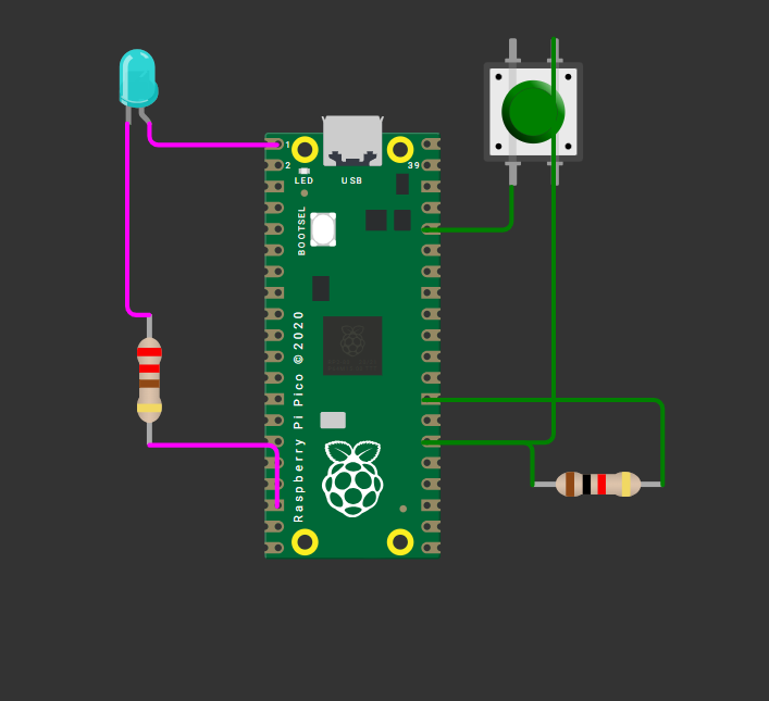
After being able to get the code to work, I decided I should add a button that would play the code when held down. I added a button and then I connected the button left leg(btn 1:2.r) to the 3v3 pin which provides power and then I connected the top right leg(btn 1:1. l) to GP20. Then I had to connect the resistor so I connected one end to GP20 and the other to a GND pin. This setup means that when the button is pressed it allows the LED to follow its code.

Now I had to code for the button to actually do what I want it to do. I did this by using digital read (20) which tells it that when pin 20 is getting power to it, it will do the code that is below it. This means when the button is pressed, the LED will get brighter and then turn off and repeat that until the button is let go.
      void setup() {
        // put your setup code here, to run once:
        pinMode(0, OUTPUT);
         pinMode(20, INPUT);
      }


      void loop() {
        // put your main code here, to run repeatedly:
        while(digitalRead(20)==HIGH){
          analogWrite(0,0);
         delay(1000);
          analogWrite(0,100);
         delay(1000);
         analogWrite(0,300);
          delay(1000);
         analogWrite(0,500);
          delay(1000);
      }
      analogWrite(0,0);
      }
Useful links