12. Mechanical Design
Hero Shot of the Week

Summary
How to have fun when I finally meet my FabAc peers in IRL.
Work Process
Calendar
| Date | To be done | What was done |
|---|---|---|
| Thursday | - 10h local meeting | |
| Friday | - FabLab normal work | |
| Saturday | ||
| Sunday | - traveling to Amsterdam | |
| Monday | ||
| Tuesday | ||
| Wednesday | ||
| Thursday | - back to bxl | |
| Friday | - FabLab normal work | |
| Saturday | - documenting | |
| Sunday | ||
| Monday | ||
| Tuesday | - FabLab normal work | |
| Wednesday | - 12h Local - 13h Regional - 15h Global |
Introduction
Introduction made by Saco.
EU machine definition 2006/42/EC
DOF & Stability
Brainstorming
On the design of the robot.
Quotes while brainstorming (and sketching on paper):
That looks like a butt hole
Someone drunk trying to be quiet
Now its getting weird
The creature lives inside the USB port
(Giving no context is so funny)
A Shy Xiao.
Waag-E
I would like to put more images here but there is a high chance of copy right issue

Work Process
Sam:
- Stepper Motor Code
Irja:
- Robot Skeleton
- Robot Housing / Casing
- Wheels
- LED
- Stepper Motor Code
- Servo Motor Code
- Robot Skeleton
- Wheel Connection
- Eye Mechanism
- Eye Housing
Making the skeleton (and housing) of the robot:
Skeleton
We first started disassembling older robots and other stuff to have materials to work with.

While disassembling I started to found a new way to connect the motors from an old project with our project. I wanted to move the attachment (the part that connect the motor to the body) part as it was taking up quite a big space and we were loosing a lot of the shaft length of the motor. So I did some CAD design and laser cutting.
After the disassembly of several stuff, we started to create the main frame of the robot. This is when Henk gave us two boxes of extruded aluminum and stepper motors. At this point we decided to go with the new stepper motors so the new mounting mechanism that I was working on was for nothing.
We did the main frame, attached the motors and added a carton to visualize how we want to go on.

For fixing the wooden lasercut plaques I modified T-nut from Printables

HC-SR04 Ultrasound holder
I sometimes helped Irja with the housing. It was mostly with little details like the sensor attachments. For the ultrasound sensor HC-SR04 I took the pin design that Irja made and modified it. Than used a heat gun and a 45° angle thingy to bend it.

And for the sensor casing I just went onto thingiverse and a suitable model for us. Why design something if it already exist.
HC-SR04 Casing + Angle Adjustable Cradle
The first print I had an issue were the holder part was too small, and one of the leg broke. So I made it bigger in prusa slicer and changed the position so the layers would be stronger.

To be honest, as an engineer I just quickly wanted to prototype. So I did not gave any thoughts to the color of the filament. Sorry 😅
Repairing / Creating the wheels
Before going to Amsterdam I 3D printed the wheel parts that I was asked to. The wheel we used where from thingiverse
Than when we decided to change to the stepper motors we also needed to create a new axial connector. (The thing that connects the motor shaft to the wheel.) So I took measurements of different parts and created a CAD design. The design differs from the previous group by several factors
- The motor metal shaft goes in way deeper.
- The 3D model has a flat part as does the shaft
- We printed it sideways to have less weak points

I printed several prototype with the Ultimaker but somehow none of them were any good. So Irja printed it with her own 3D printer, and this time it worked. (It was not the first neither the last time that the Ultimaker printer gave us issue.)
I also search on how the wheels needs to be mounted and found this picture:

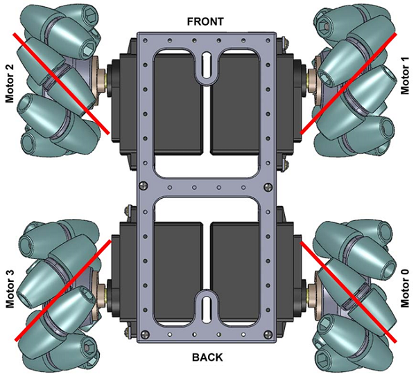
Eyes
Another work was figuring out the eyes and their movement.
Eyes
For the eye itself I 3D printed it with uncolored PLA.
The files used are from here
So thanks Ikkalebob for your work.
Mechanism & Gears
Than I started thinking about how to make them move. We wanted to have them move up and down separately. And also to make them turn. So I needed a gear system.
So I thought that I would need a cylinder gear for the up and down movement. And a normal gear at the bottom for left right movement.
For that I started to do some internet search to how to create gears in Fusion. And hold and behold, there is an app for it in the store: GF Gear Generator
Than I played around with it to understand how it works. After that I did some prototyping.

In the meantime we also changed from one type of motor to a servo motor SG90
When I was satisfied with the base gear connections I did a 360 turn with the flat gear to make it into a cylinder. The cylinder needed to have a middle shaft. As I wanted it to be able to turn the shaft needed to be not cylinder. As we had some wood square rods I made it square.

When first assembled I still needed to sand down the wooden rod so the cylinder could smoothly go up and down. And also to cut it to the right length.
Casing
I also needed to create the box in which all of this will be housed.
The first iteration had an issue where the servo motors did not fit...
So I made a second one with bigger kerf.
(The first iteration was still used as a bottom plate for the bearing not to fall out at the bottom.)
Than because the gearing was still moving (the wood was half the width of the bearing) I created a small square support to stabilize it.
In the end we also added some error 404 name not found to have the bottom gear at the right hight compared to each other.
(The image bellow is from the last iteration.)

The issue was that the Ender 3D printer had issues printing it so Irja printed it at home.
I had a miscalculation... I did not take into account the hight of the Eyes. So the case had the right hight to hide the mechanism but the eyes where sticking out...

So I quickly made a second box that would just be put on top of the existing one with four legs that would go to the bottom. With this second box, while Dylan was working with the servo motors and mechanism (the assembled first box), I could work with the hinge.
So I found a hinges on Printables I had some printing issues with the Ultimaker. But this time it was because I did not notice that the print bed became loose.

Connection
Than we needed to connect the eyes to the cylinder. For this, I first checked Ikkalebob work to see if I could reuse something. In the end I created my own adapter.

I had an issue with the Ultimaker were the first half printed well, than from a certain hight it just did shit. This was the point where I asked Henk if I could fix the Prusa printed. He said yes. And now we had a good printer that I fully knew how to use.
To connect the two part (cylinder and socket) I just super glued them together.

Make It Glow
As the eyes itself were translucid Irja made a PCB to have an RGB LED. I helped her debug the LED as the connections given in the footing from the FabAc library did not match up with the footing from the datasheet.
And than I super glued it to the eye holder.
What could be improved
- So the wheels need an overhaul as some of the parts broke (I was not there anymore but it is visible in the video).
- The casing for the eyes could be improved so that the exes are completely hidden and more to scale with the body.
- The eye moving mechanism could be modified so that each eyes can have independent movement from each other.
- More LEDs. For once the LEDs that are present on the real board are not on the bigger one. For second LEDs are cool. More cannot be bad.
- Trying to make it lighter could be a possibility too.
- Having it autonomously move around with distance sensor to detect its surrounding. (As our original idea, that we did not have time to finish).
Learning Outcome
Creating more complex mechanism.
Groupe work, time management, distributing work.
Having fun with the others even if you want to smash something because what you are doing does not work.
My Digital Files and Links
Assignment Check
- design a machine that includes mechanism+actuation+automation+application
- done
- build the mechanical parts and operate it manually
- done
- document the group project and your individual contribution
- done