Output devices
Group project
"measure the power consumption of an output device"
Henk used the lab's DC power supply to measure how much power output an LED strip would draw on different settings.
5V + 500A = the LED strip turned off after ~70% of the LEDs turned on.
5V + 800A = the LED made it through the red + green + blue + flashing displays, but when the multicolored routine started, the strip turned off.
5V + 1A = the LED was able to stay on throughout all of the display.

We also used an app, called Ampere, on Sam's phone to test how much power our circuits from Input Devices week were drawing, but we weren't sure how reliable the results were.

The app measures the discharging current of the Android device's battery. However, the readings we got didn't match up with what we read on our multimeter. It's likely that the phone was also being drained by the software and hardware components.
Individual project
A Beginner's Guide to Choosing & Using Motors, Servos and More
Motor types
For my project, I decided to try using stepper motors. Click to see the pros and cons of the three most common motors in hobbyist mechatronics.
Servo motor
- Pros: Simple to control, good for automated seats with slow and smooth movement
- Cons: Limited weight capacity, may struggle with very heavy seats, limited range
DC gear motor
- Pros: Stronger than a servo, smooth motion, can be used with limit switches for precise stopping
- Cons: Requires a motor driver circuit, powered and not spinning = stalling which will destroy the motor
Stepper motor
- Pros: Precise control, good for slow & controlled lifting
- Cons: Needs a driver (e.g., A4988), more complex than DC motors

NEMA 17 stepper motor
I decided to use a NEMA 17.

17HS19-2004S1: A Nema 17 bipolar stepper motor with high torque.
The NEMA 17 motor is rated at 2A per phase.

The DRV8825 driver can deliver up to 2.2A per phase.

DRV8825 Step stick
I begun by setting up the circuit up using a breadboard.
There are lots of tutorials online. However I struggled to get the motor to respond. Below are two that I attempted.

Stepper Motors and Arduino - The Ultimate Guide:

The issue was that I hadn't grounded the motor power supply and logic power supply correctly. The following schematic worked (kind of), I was getting a response from the NEMA 17, but it wasn't such a nice sound.
This was the layout that worked:
DRV8825 Stepper Motor Driver – Complete Guide (YouTube / website).
NB. DO NOT INCLUDE THE CABLE WITH the 'x' through it. That's how I fried my Arduino Uno.

A neat trick for figuring out which pins are connected on a stepper motor. Plug a cable into two of them and find the ones where the motor turns less freely.

Current limiter

Set the current limit to avoid exceeding your motor current limit (here's a video from Pololu on how to do that):
Current Limit = VREF × 2
NEMA 17: 2.0A per phase
2.0A = VREFx2
VREF = 1V
Calculate the Vref before plugging in the stepper motor.

TB67H451 stepper driver
On of the objectives for this week was to "Add an output device to a microcontroller board you’ve designed and program it to do something."
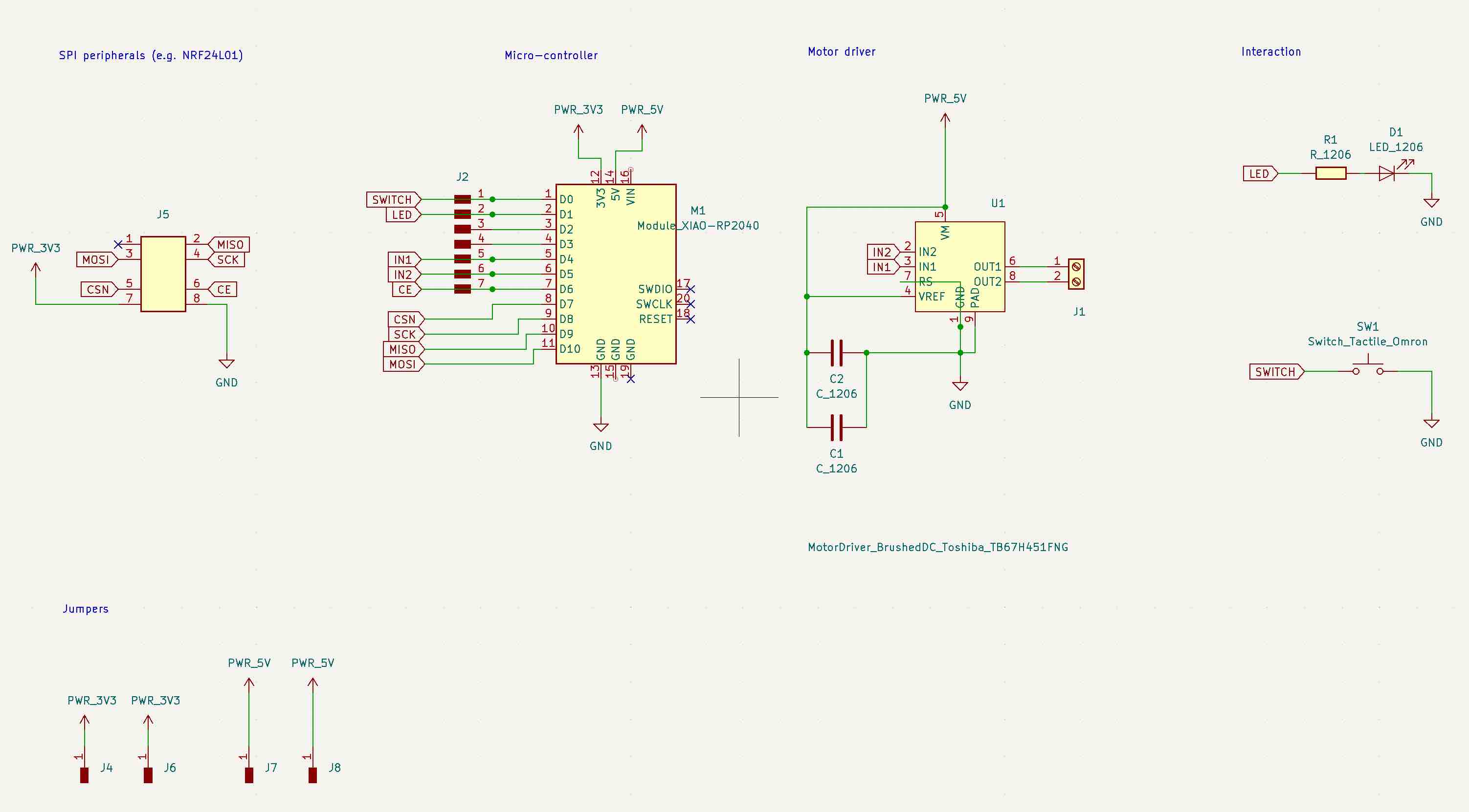
Henk suggested that I design a board with TB67H451 stepper driver on it.


RS= Motor Output Current senseVM= Motor Power SupplyVREF= Motor Output Current Setting PinPAD= Thermal Pad
In the datasheet, from Toshiba, there is a schematic for how to use the part to control a stepper motor.
The stepper driver only has two output pins, which would get the motor to move in one direction. A stepper motor is able to move backwards and forward though. I would need a second stepper driver in my circuit design to do that.

"Furthermore, the TB67H451FNG has two inputs, IN1 and IN2, which are capable of selecting of the four operation modes; forward (clockwise), reverse (counter-clockwise), short brake, and stop modes."

These are the capacitor suggestions from Toshiba.

I followed the project Neil showed us in the global lecture when deciding on a few factors about the circuit's design. In this case, I used 0.1uF and 10uF capacitors.

I referenced a previous student when designing my schematic. In hindsight, I should have stuck to just following Neil's example, exactly how he did it, before branching out and trying to incorporate the ideas of others.
NB. From the datasheet of the stepper driver: "In order to disable the constant current function, RS pin should be connected to GND, and the voltage of 1 to 5V should be applied to VREF pin."


Kicad files
Some NB. about Milling

To fix this, I used a blade and a tweezers to cut + scrape away the traces. Not a pretty solution, but one that worked.
Notes to self:
- Beware of 45 degree angles
- Always check the Mods filepath before milling
- Don't "Fill edge cut" on the F.Cu file (gerber-2-PNG)
Arduino code
Since I added a button to my design (without a board mounted pull up resistor), I had to make sure the XIAO RP2040 internal pull up resistor was activated.
Here's an example code for how to do that:
#include <Arduino.h>

const int buttonPin = 2; // Example: GPIO pin 2

void setup() {
  Serial.begin(115200);
  pinMode(buttonPin, INPUT_PULLUP); // Enable internal pull-up resistor
}

void loop() {
  int buttonState = digitalRead(buttonPin); // Read the button state

  if (buttonState == LOW) { // Button is pressed (connected to GND)
    Serial.println("Button Pressed");
  } else {
    Serial.println("Button Released");
  }
  delay(100);
}
The button worked!
However, the stepper driver did not...
Debugging
The input pins of the stepper driver were connected to digital pins, rather than analog ones. I changed that by rerouting them.

The H-bridge in the stepper motor isn't delivering current through the output pins:

I decided to go through the datasheets again, more slowly.
Here's a list of the pins.
- VM: Power supply voltage for the motor drive circuitry.
- GND: Ground connection for the IC.
- IN1, IN2: Input pins for controlling the H-bridge, likely used to control the direction and speed of a motor.
- OUT1, OUT2: Output pins connected to the load (e.g., motor).
- VREF: Reference voltage input, often used for setting a voltage level for internal comparators or control circuits.
- RS: Current sense resistor connection. This is used to measure the current flowing through the H-bridge for current limiting or regulation.

I tried testing the circuit with a DC motor.
I tried testing with different components: motor, stick, cables, etc.
I tried a few different example codes.
Nothing worked.
Some success
On Friday afternoon I reverted back to using a stepstick. The issue with my previous attempts seemed to be a matter of incorrect grounding.
This is how everything is plugged in (to refer back to, if need be).


This is the code that I used which worked.
#include <AccelStepper.h>

AccelStepper stepper; // Defaults to AccelStepper::FULL4WIRE (4 pins) on 2, 3, 4, 5

void setup()
{
   stepper.setMaxSpeed(1000);
   stepper.setSpeed(50);
}

void loop()
{
   stepper.runSpeed();
}
NB. Accel Stepper library is your friend. It's worth revising when trying to understand what the above code is doing.
Then, Sam helped me make the stepper work even better. Instead of using the default Step and Dir pins, I added: AccelStepper stepper(AccelStepper::DRIVER, D1, D0);
#include <AccelStepper.h>

AccelStepper stepper(AccelStepper::DRIVER, D0, D1);

void setup() {
  stepper.setMaxSpeed(1000);
  stepper.setSpeed(50);
}

void loop() {
  stepper.runSpeed();
}
Muuuuuuuch smoother.
P.S. ezgif.com is a nice website to edit down gifs.
I added #define M0_Pin 6 and got the microstepping working.
   pinMode(M0_PIN, OUTPUT);
   digitalWrite(M0_PIN, HIGH);
Microstepping
I checked setting M0 to HIGH while M1 and M2 are set low = 1/2 step mode.
I swapped the pin from M0 into M1 and then M2 to check the other step modes.

If you've made it this far, there's more about getting the stepper motors to work in the Networking + communications week's notes.
Final project
For this week's assignment I got the stepper working, but hadn't created my own board. Later in the course I made a few boards that were capable of powering output devices. The video below is of my final project.
The board on the right is the one that I designed to control the stepper + servo motors of my toilet seat lifting machine.
The PCB includes a DRV8825 stepstick, ESP32c3 / c6, a DC stepdown converter, 100uF electrolytic capacitor, and more! There's more information about all of it on my final project page.
