
 |
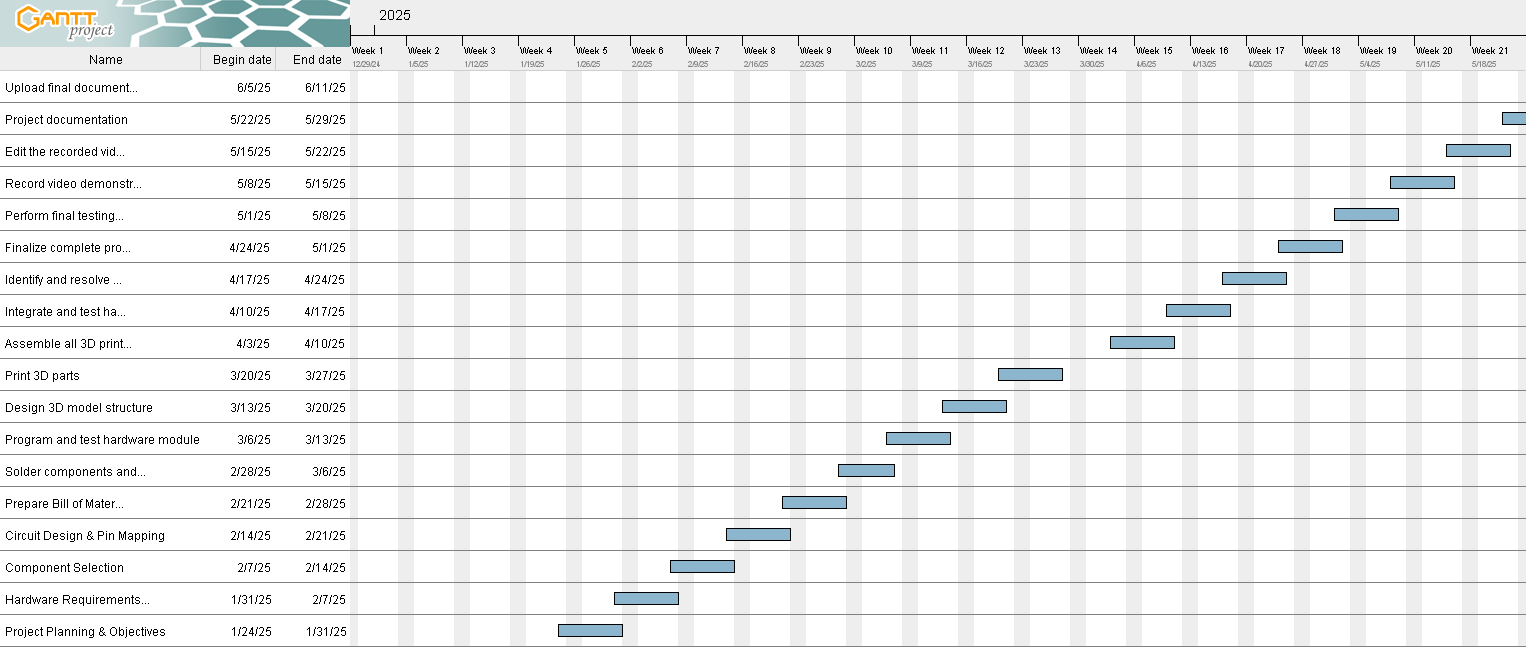
Project schedule & Gantt Chart
|
| Project Gantt chart & schedule file here |
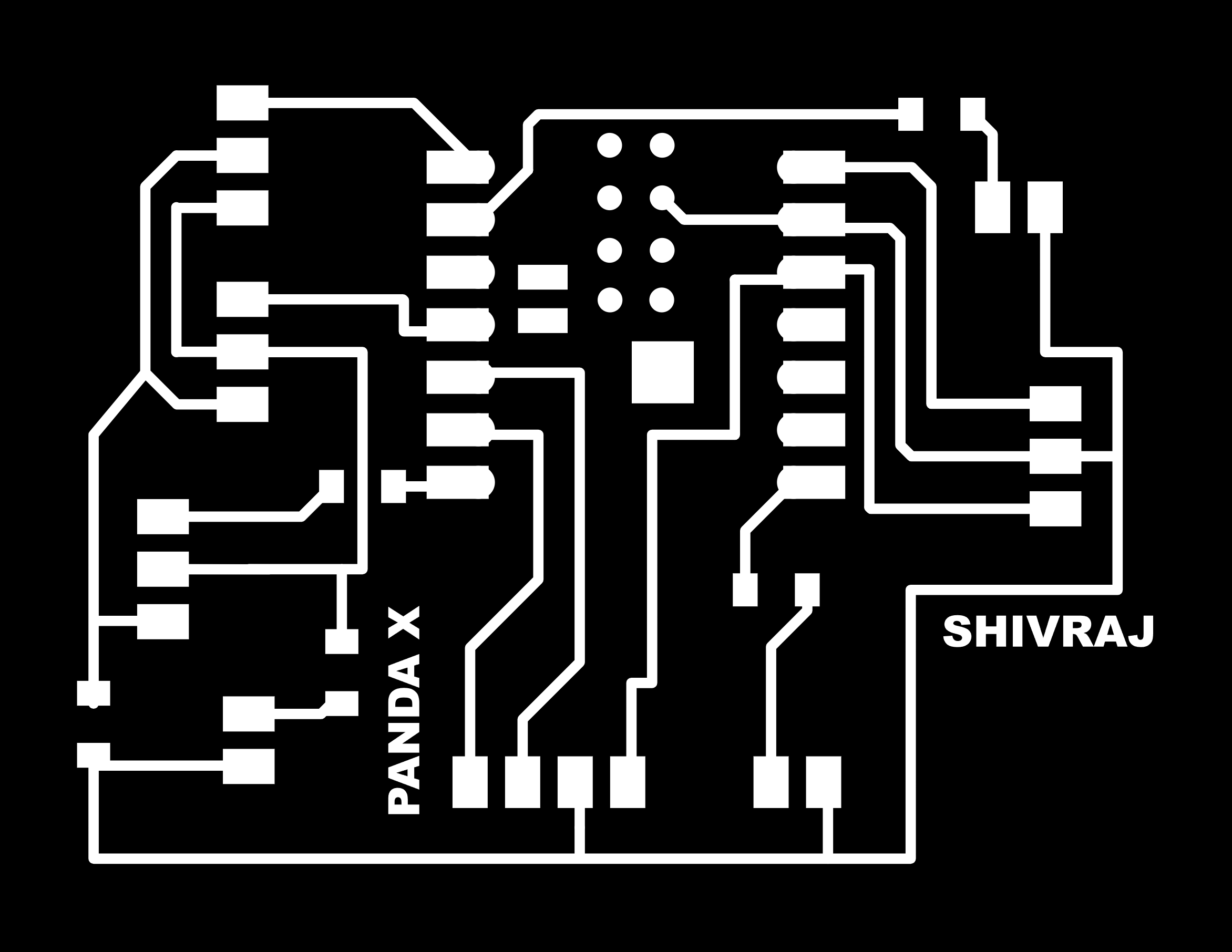
PCB Design
|
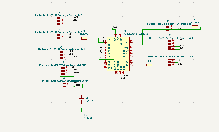
| PCB Designing and Placement of Components in Schematic section. |
|
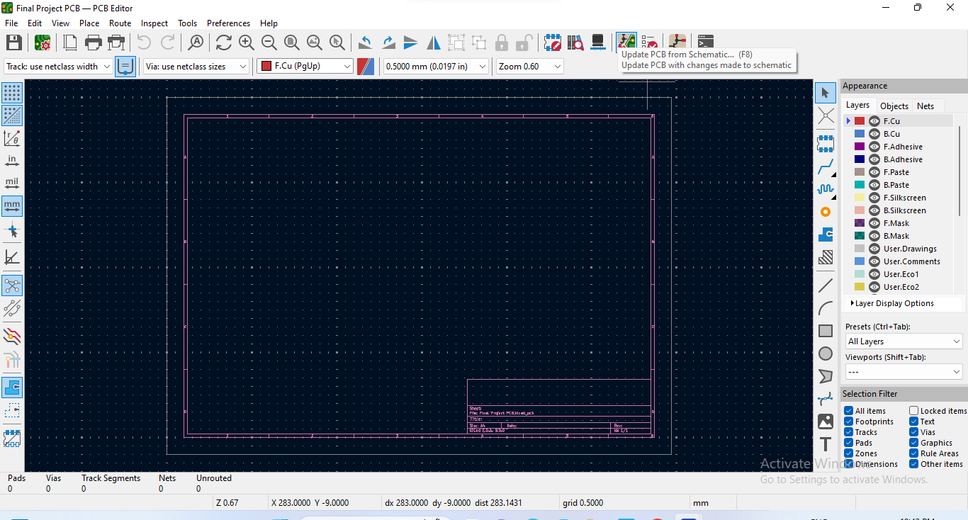
| Proceeding to the PCB Editor Section. |
|
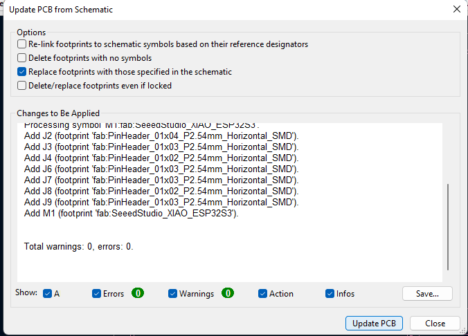
| Updateing PCB from the Schematic Section. |
|
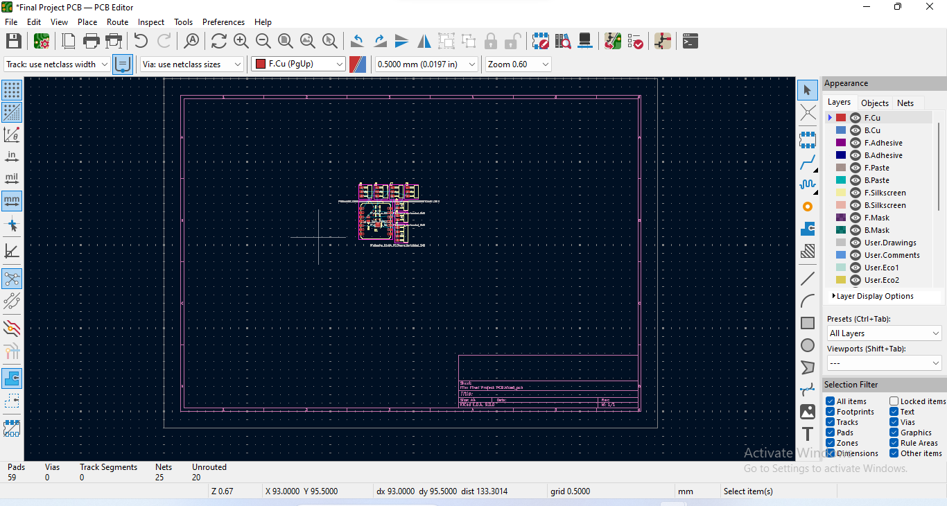
| Updated PCB |
|
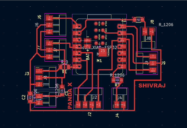
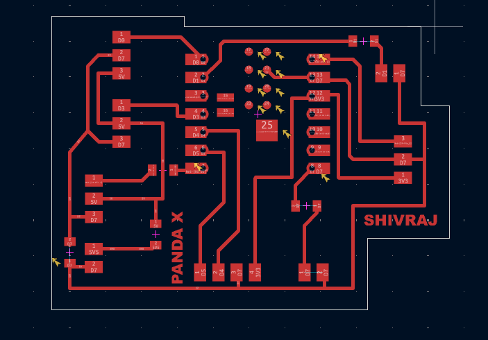
| In this step, all the electronic components were carefully placed in their appropriate positions on the PCB, following a logical and organized layout. Proper placement is crucial to ensure efficient routing, minimize interference, and maintain a compact design. |
|
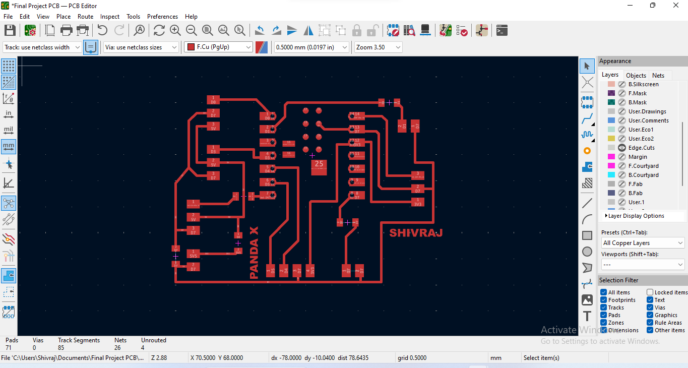
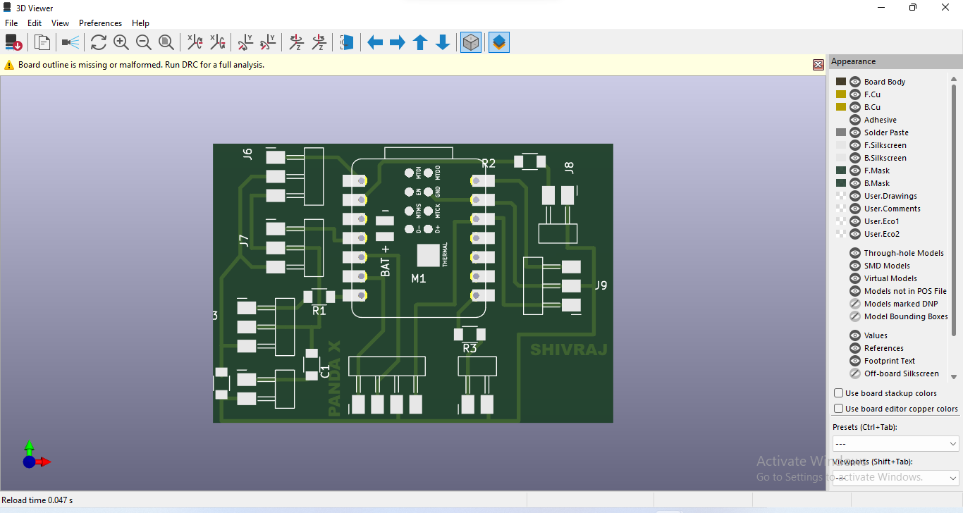
| All unnecessary parts were hidden, and only the copper layer was kept visible to ensure the PCB is displayed clearly and prints properly. |
|
| After that, the PCB was viewed in 3D mode to visualize the final design and check the placement of all components accurately. |
|
| Then, the edge cut was made to define the exact dimensions and shape of the PCB for final fabrication. |
|
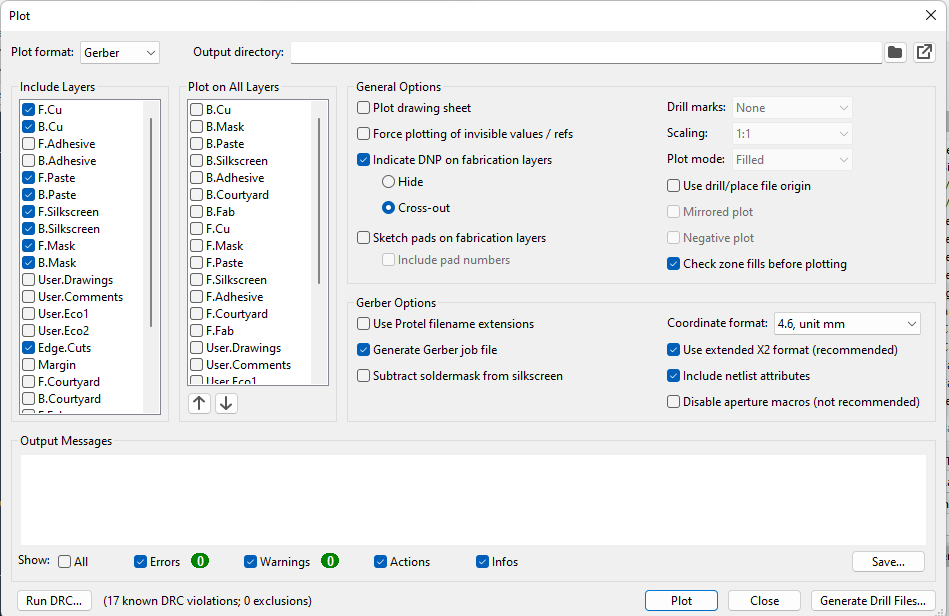
| Finally, the PCB design was exported as a Gerber file, which is the standard format required for PCB manufacturing. |
PCB Milling ( SRM 20)
For PCB milling, I first downloaded the design in Gerber format and then converted it to PNG format using an online tool (link provided below). After that, I used Mods CE to generate the toolpath from the PNG file and downloaded it. Finally, I used the VPanel software to operate the milling machine and started the PCB cutting process.
Gerber to PNG and SVG formet converter here
|
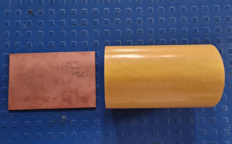
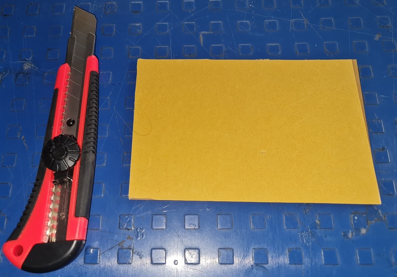
| Using FR4 PCB Material and Masking Tape |
|
| The masking tape was carefully applied to the back side of the PCB to hold it firmly in place during the milling process. Using a knife, the unnecessary or excess tape around the edges was neatly trimmed to ensure a clean and precise setup for cutting. |
|
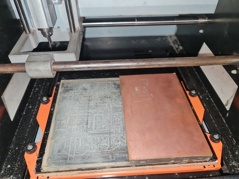
| The PCB properly fixed on the milling machine bed to ensure stability and accuracy during the cutting process. |
|
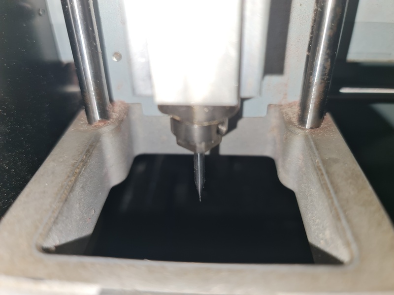
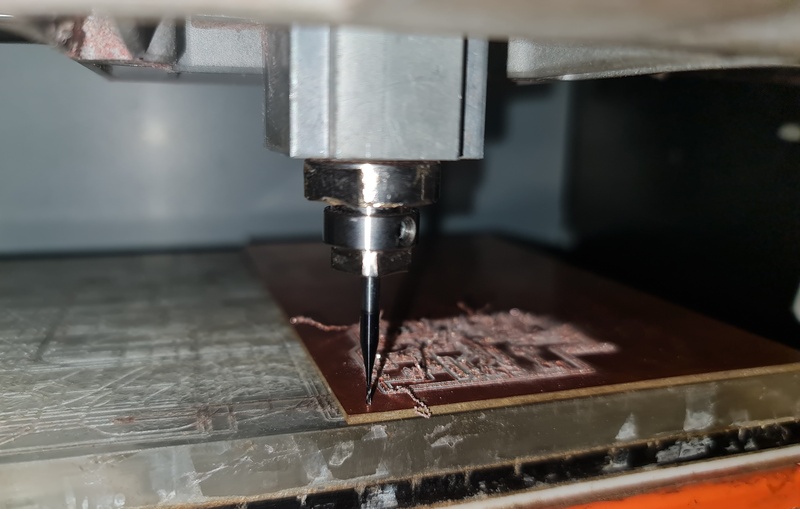
| 1/64-inch bit was putted for tracing the PCB. |
|
| Then, the bit was set on the bed to level it properly for accurate cutting. |
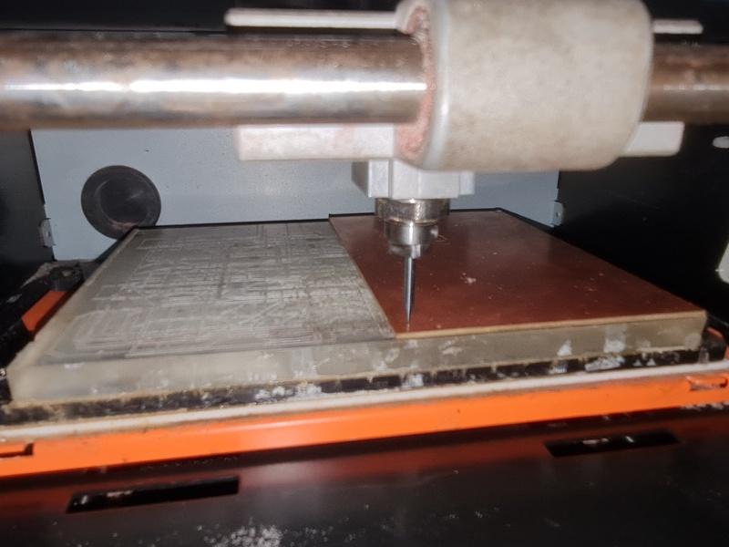
Started the machine for trace cut
|
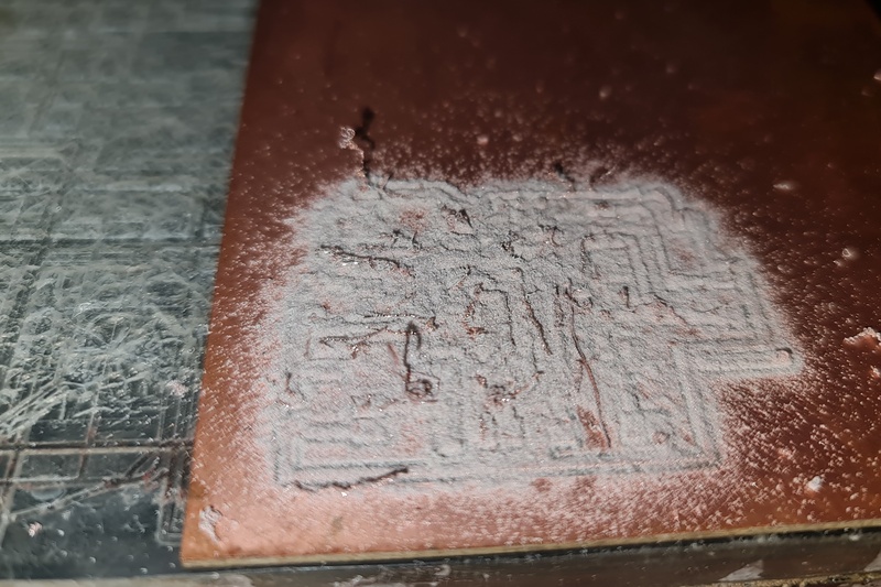
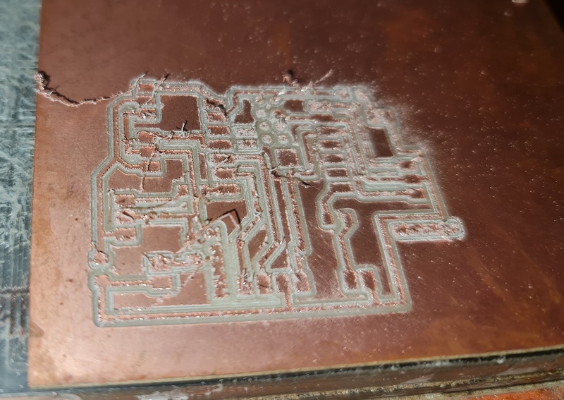
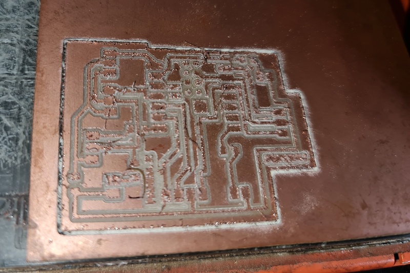
| Trace cut complated. |
|
| Once the PCB trace was milled, the surface was cleaned using vacuum cleaner to remove dust and ensure the traces were clearly visible. |
|
| After that, the bit was changed to a 1/32-inch bit for edge cutting, and gravity leveling was checked again on the machine bed. |
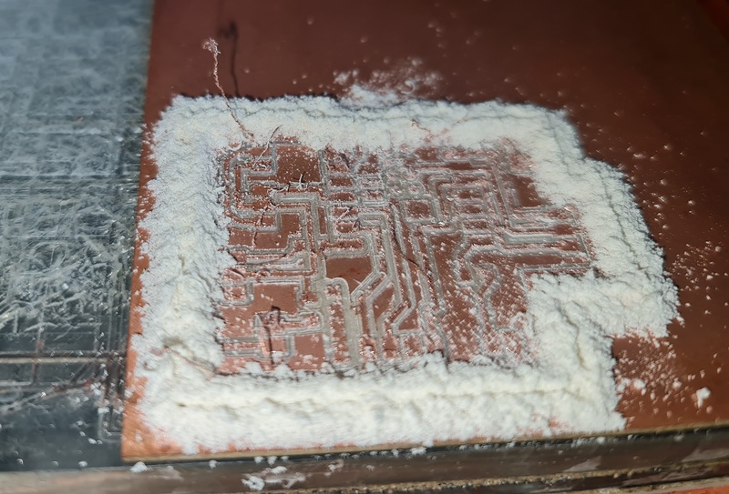
Started the machine for edge cut
|
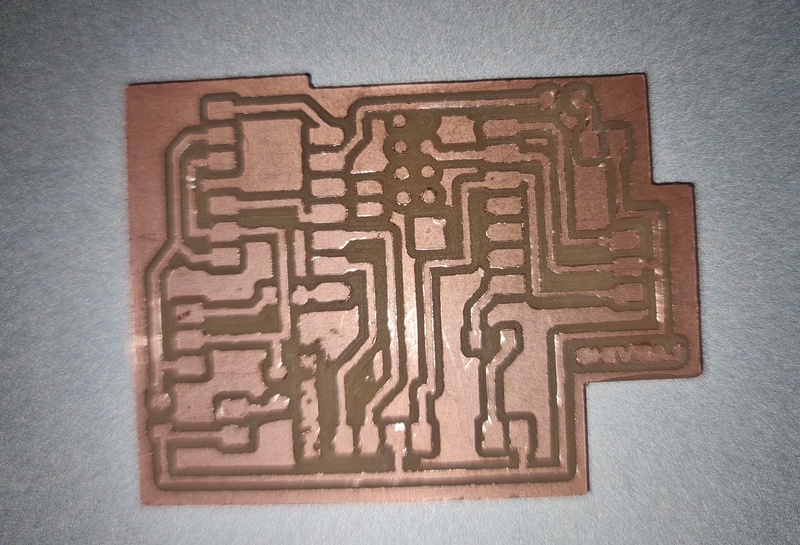
| Edge cut completed. |
|
| Once the PCB edge cut was milled, the surface was cleaned using vacuum cleaner to remove dust and ensure the traces were clearly visible. |
|
| Finally, the PCB was removed from the machine and thoroughly cleaned using a brush. |
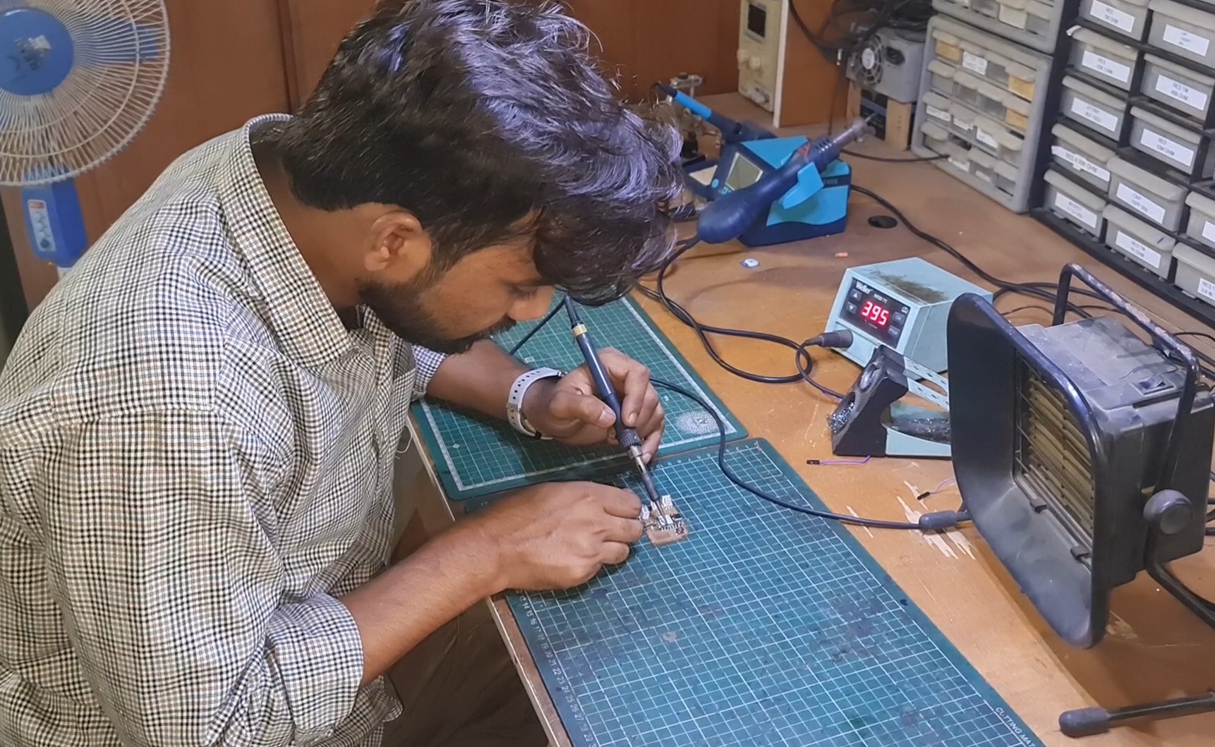
PCB Soldering
|
| After completing the PCB milling process, I started soldering the components onto the PCB. |
|
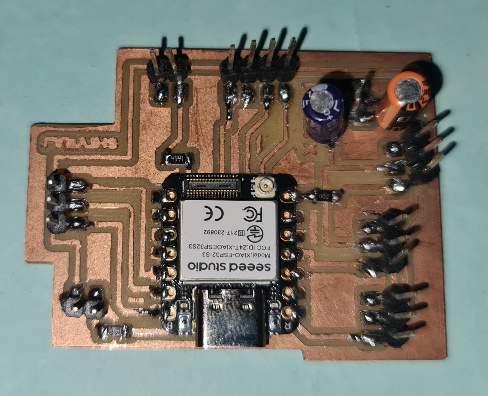
| The PCB was fully assembled with all components soldered in place. |
Hardware Parts using in this project
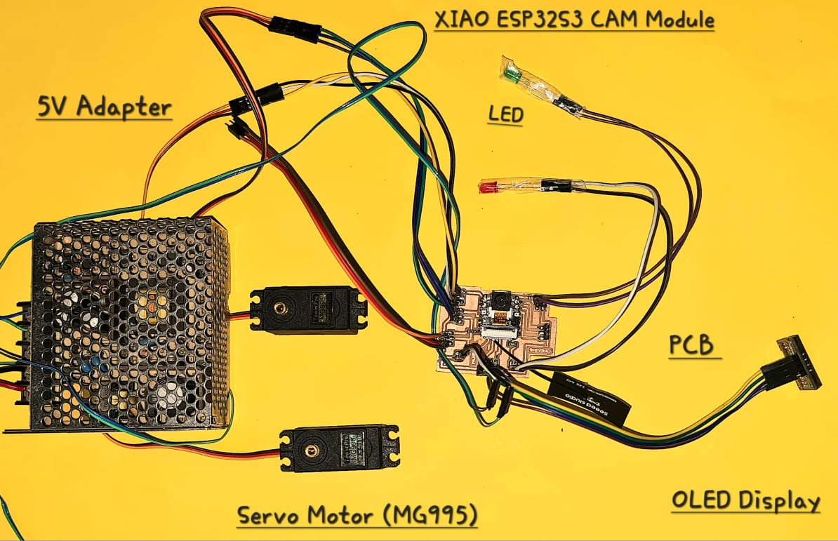
|
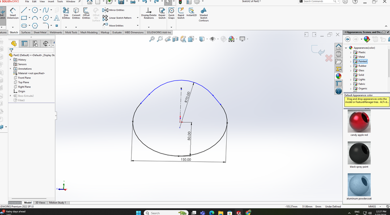
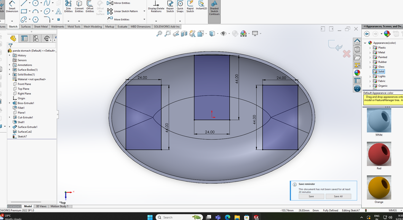
3D Designing Panda in solid work
I have started designing a 3D model of a panda using SolidWorks
 |
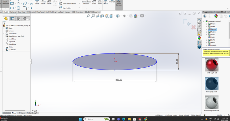 |
| First, I used the Line Tool in SolidWorks to create the shape of the panda's mouth. | After that, I completed the shape of the panda's belly. |
 |
 |
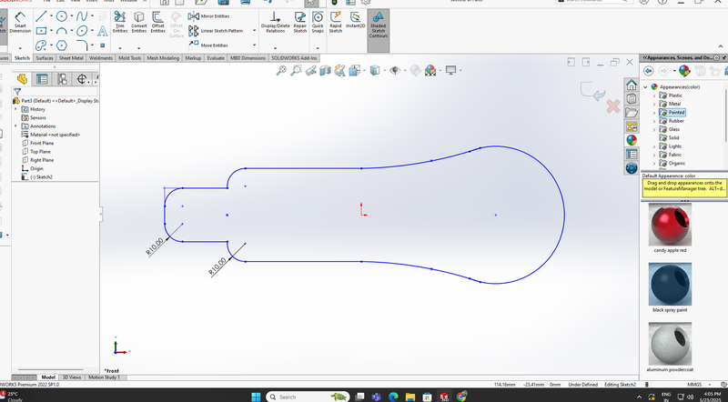
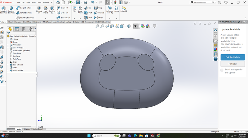
| Then, I started designing the panda's arms. | Now, on the back side of the panda's belly, I created a housing to place three servo motors. |
 |
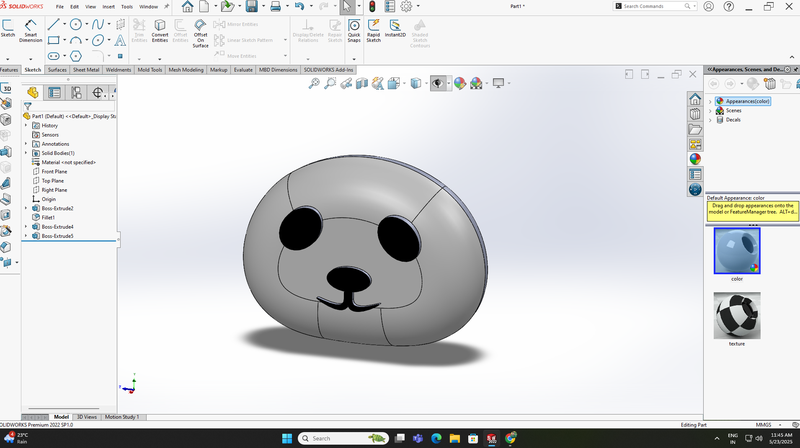 |
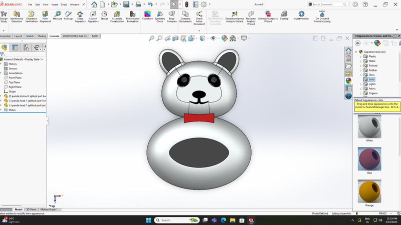
| After that, I drew two circles on the face area to create the shape of the eyes. | After finishing the eyes design, I drew the nose and mouth, then colored them. |
 |
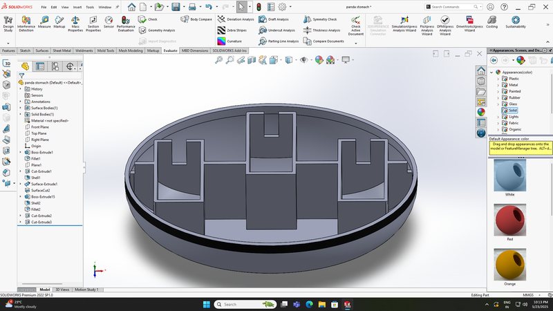 |
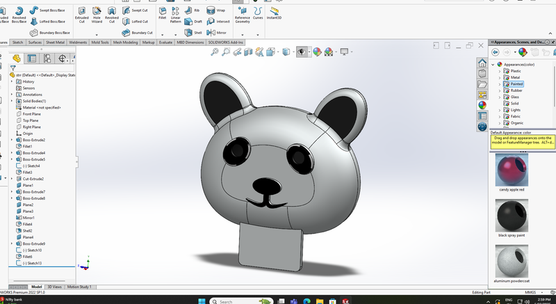
| Then, Designed the ears and neck on the panda's face | Then, I extruded and completed the design I had drawn earlier for the servo motor housing at the back part of the panda’s belly. |
 |
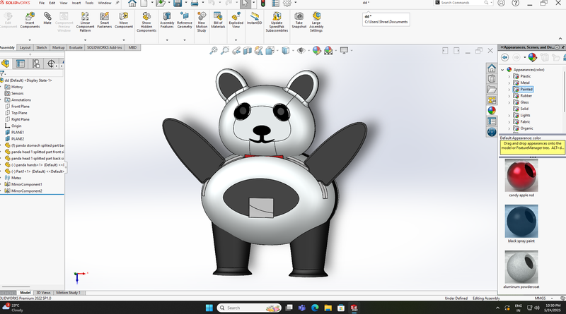 |
| Now, I assembled the panda’s face and belly together. | After completing the design of all the parts, I fully assembled the entire model. |
| View of the servo motor housing at the back part of the panda’s belly. |
| Fully assembled view of the panda’s face and neck. |
| Assembled view of the panda’s face along with the back part of the belly. |
| Full assembled view of the front and back part of the belly along with the mouth and hands. |
| Now, here is the fully assembled view of all parts of the panda, including the mouth, hands, belly, neck, and legs. |
2D Designing Panda in solid work
 |
 |
 |
 |
|
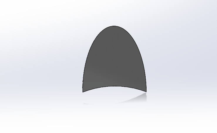
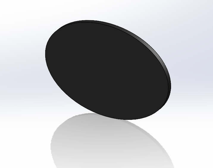
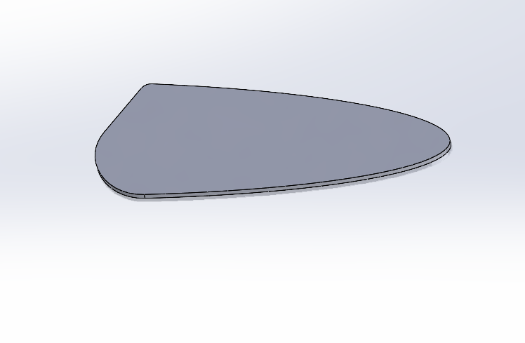
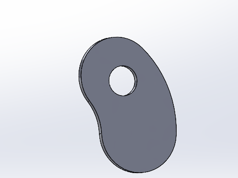
| Ear |
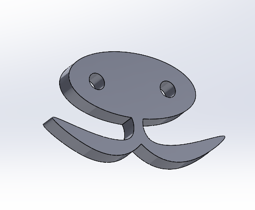
Foot |
Hand |
Head |
|
 |
 |
 |
 |
|
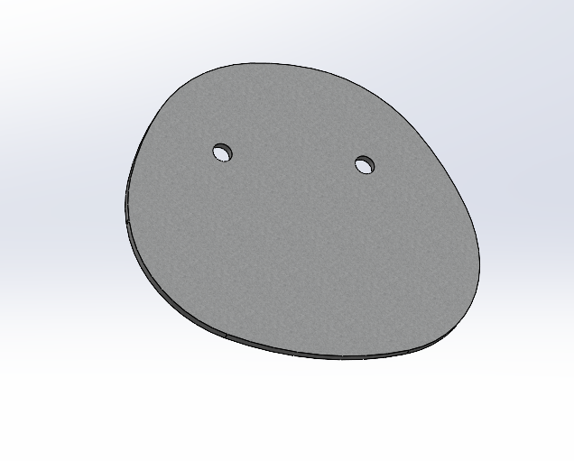
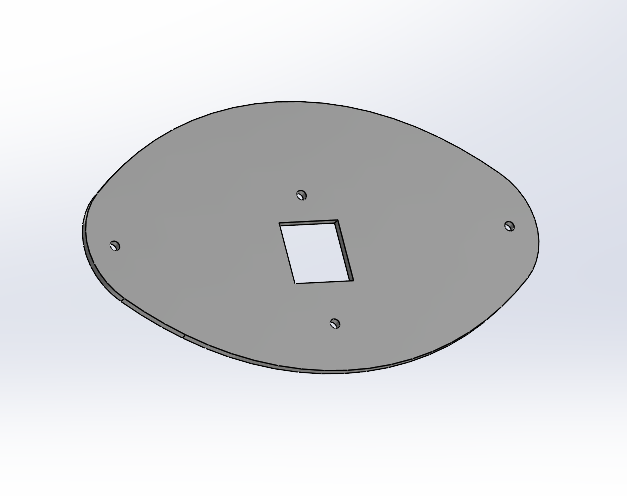
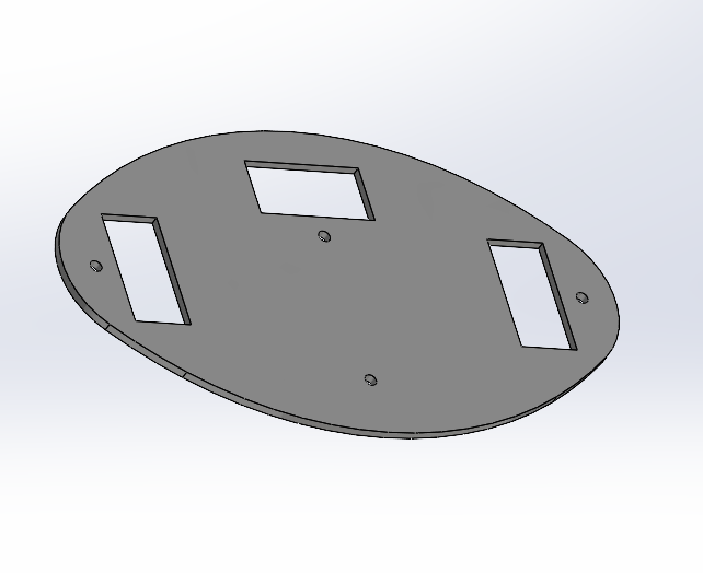
| Front Side Stomach |
Back Side Stomach |
Nose |
Eye |
|
Assembly Panda Parts with All Hardware Components
|
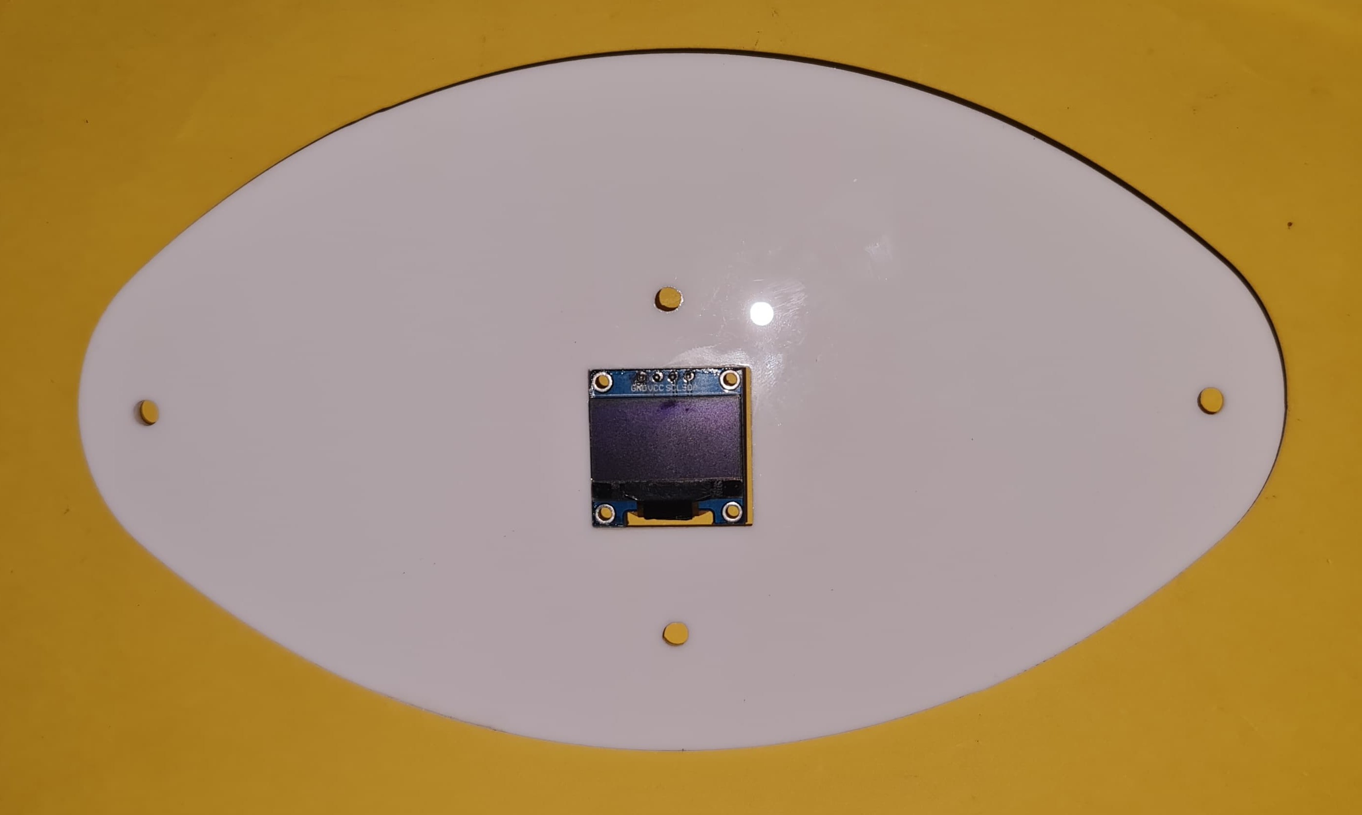
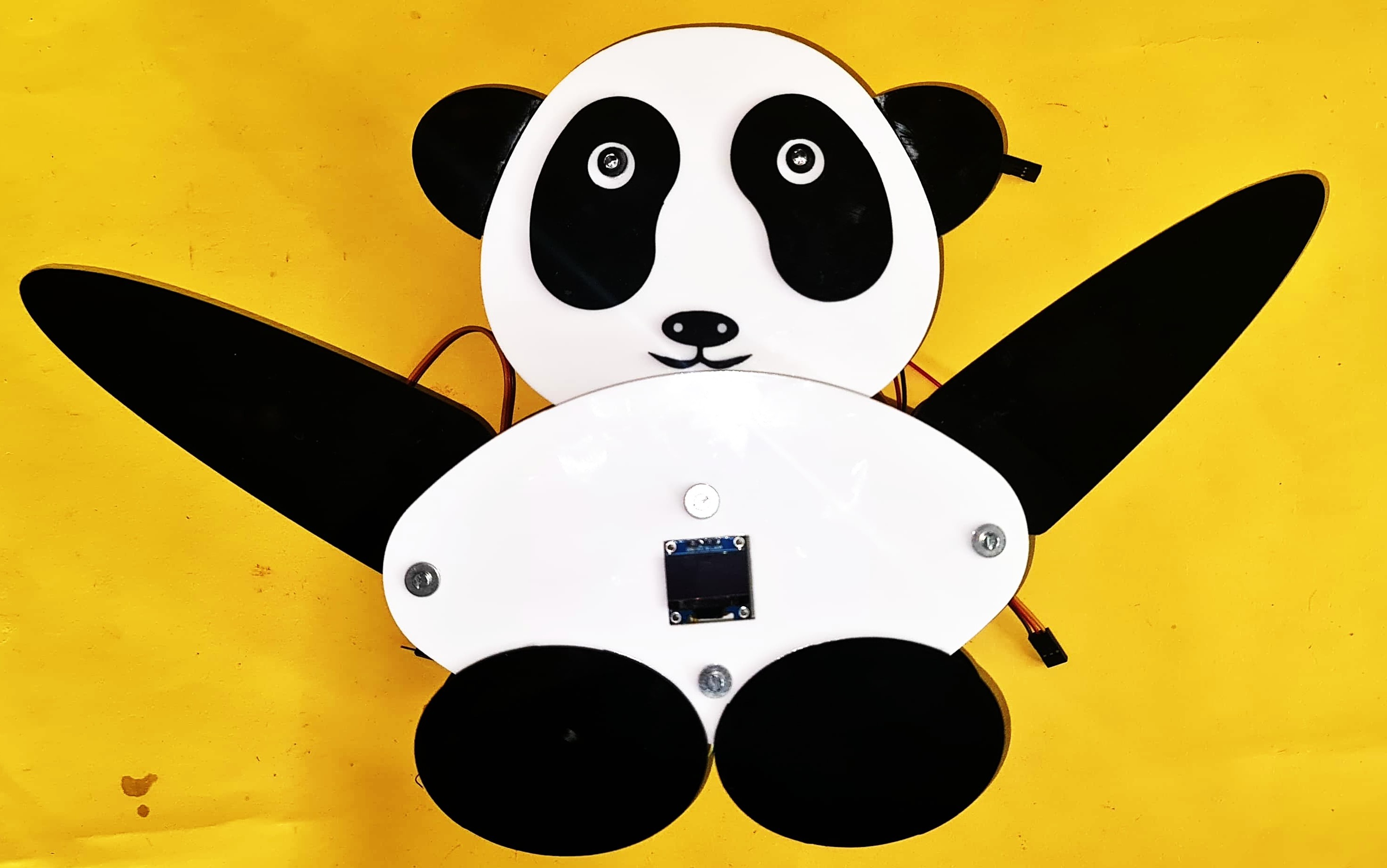
| OLED Fitted in front side of stomach part |
|
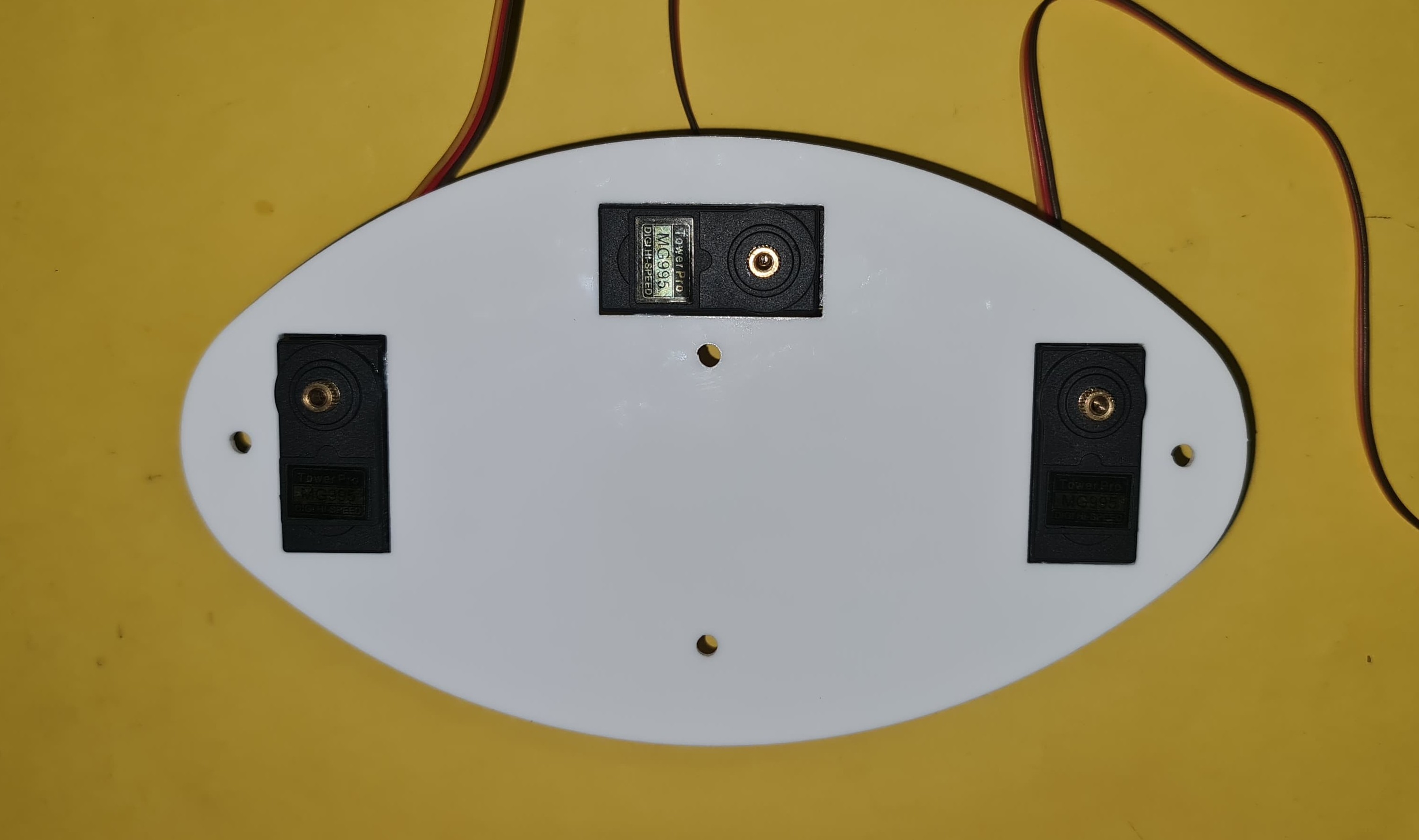
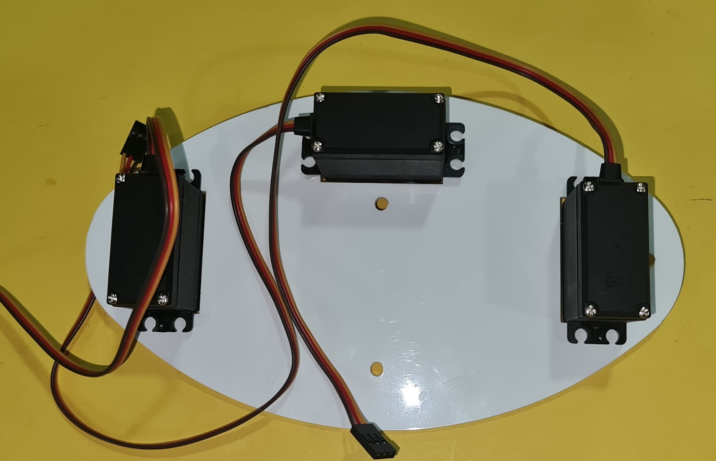
| Servo Motor Assembled on the Back Side of the Stomach |
|
| Back Side |
| Complete harwware part and 2 D part Assembling |
|
| All Components & Hardware parts fully assembled. |
Project slide for presentation
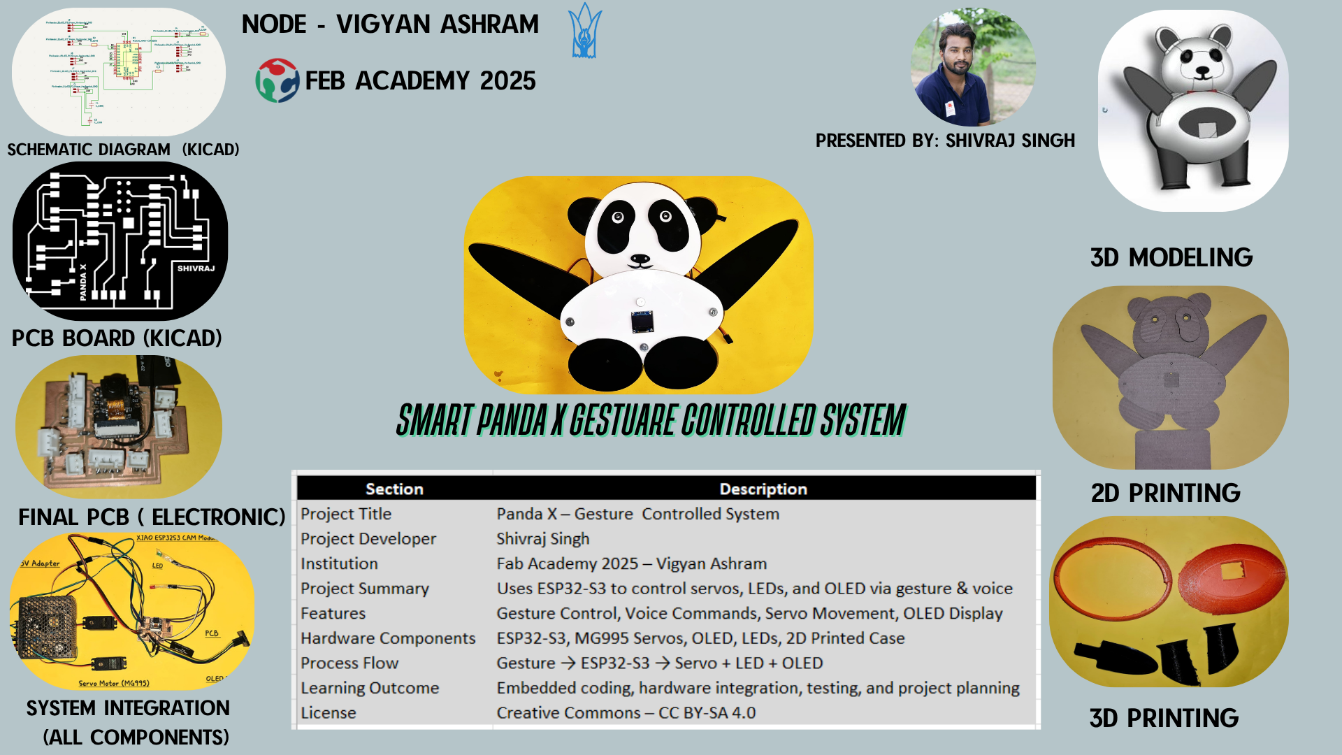 |
Final Presentation Video
Click here to visit Week 15: System Integration
Gesture and Python Code Explanation
Gesture Explanation
Panda using camera and a gesture recognition running in Python to understand hand signs
Camera and Serrial
Gesture Detection Thumbs up
Gesture Detection Thumbs down
Send Command to ESP32
ESP32 Takes Action
Code Explanation
I have provided a detailed explanation of the Python gesture controller code, with all explanatory comments clearly highlighted in black for better readability. The complete documentation is included in the attached Word file.
Python programming code explanation word file here
Original File's Given Below -
Arduino programming code here
Python programming code for gesture here
Panda 3D Design in solid work
Panda 2D Design in solid work
PCB Design in KiCad
Acknowledgment
The journey of my Fab Academy experience has truly been transformative and has introduced a new role in my life. Over the past six months, I have learned a great deal—technically, creatively, and personally. This journey would not have been possible without the support and guidance of many incredible individuals, and I would like to express my heartfelt gratitude to all of them.
First and foremost, I would like to thank Mr. Suhas Labade, the Fab Lab Manager at Vigyan Ashram, for his constant support and mentorship. My sincere thanks to Dr. Yogesh Kulkarni, Director of Vigyan Ashram, for his leadership and encouragement throughout the course. I am also deeply grateful to Prof. Neil Gershenfeld, Director of the Fab Academy, whose inspiring vision and teachings guided us through every week of this intensive program.
I would like to extend special thanks to Ms. Dipali Kamble, my local instructor, for her guidance, patience, and valuable feedback at every step. I am also thankful to Mr. Sumit Thakare and Mr. Akash Mhais, former Fab Academy students (2024), for sharing their experience and insights, which helped me tremendously.
I would like to acknowledge Ravindra Nath (Chadwick) and Mr. Umesh Imphal, DBRT students at Vigyan Ashram, who supported me during this journey. A special mention to Ms. Arti Bhosale, who manages the computer lab and was always ready to help with the required resources.
My gratitude also goes to Mr. Abhijeet Pisal, Coordinator of the DIC Department, and Mr. Pranit Sankpal, Project Professional at Vigyan Ashram, for their valuable support and encouragement during various phases of my project.
To all of you — thank you from the bottom of my heart. Your support, guidance, and contributions played a vital role in making my Fab Academy journey meaningful and successful.
Meet the mentors and friends who made this journey possible.
 |
 |
 |
 |
 |
|
| Mr. Suhas Labade |
Dr. Yogesh Kulkarni |
Prof. Neil Gershenfeld |
Ms. Dipali Kamble |
Ms. Arti Bhosale |
 |
 |
 |
 |
 |
|
| Mr. Sumit Thakare |
Mr. Umesh Imphal |
Mr. Ravindra Nath (Chadwick) |
Mr. Abhijeet Pisal |
Mr.Pranit Sankpal |