
About this week
In this assignment, we learned about electronics production, including the process of PCB milling and operating a PCB milling machine. The key objectives of this assignment are as follows:
Heroshot of the Assignment
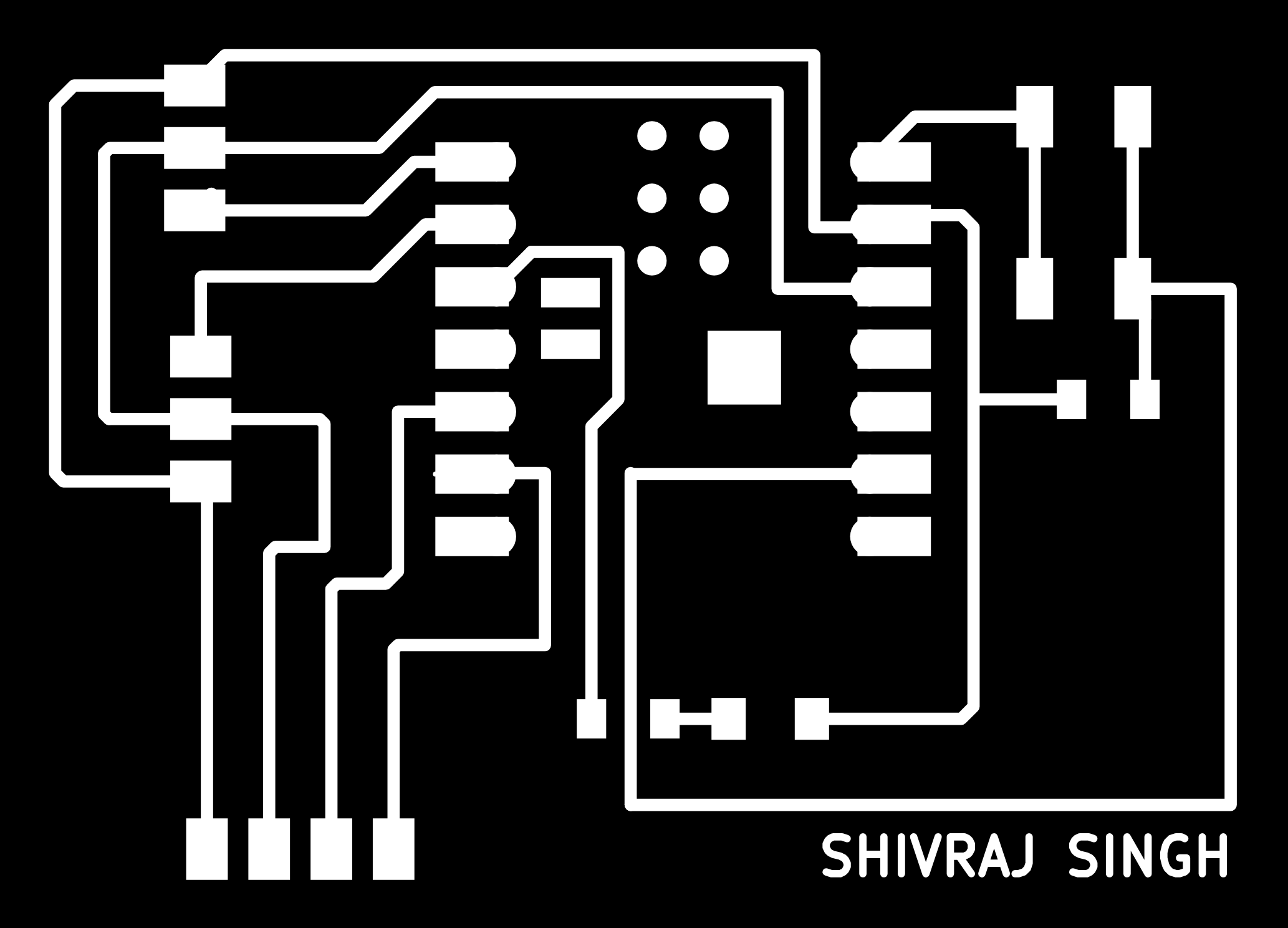 |
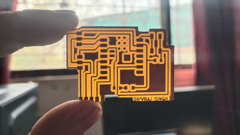 |
|
|
|
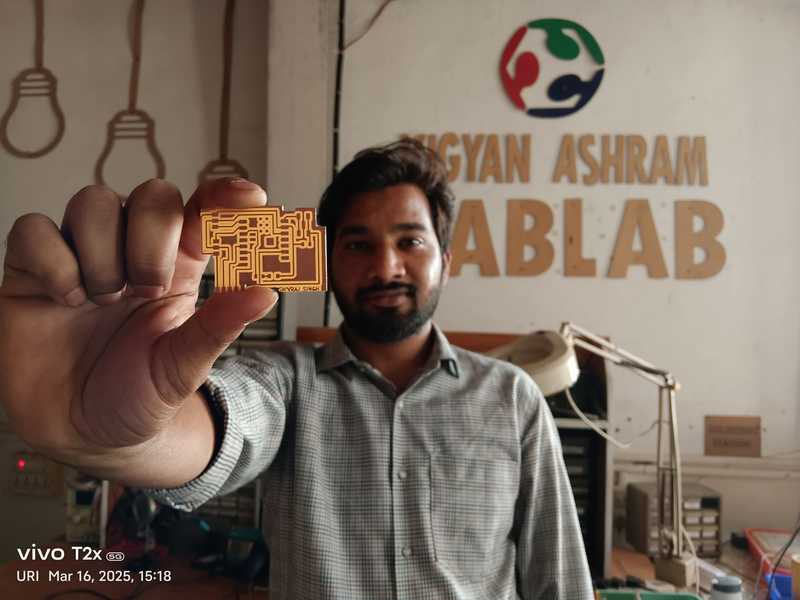 |
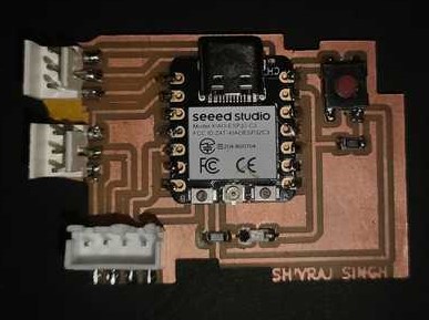 |
|
|
|
Objctive of the Assignment
1.Group Assignment -
2. Indivisual Assignment -
What is Electronics Production ?
Electronic production involves designing and manufacturing small electronic components such as resistors, transistors, and PCBs. This process includes designing the PCB, printing it, and assembling all the necessary components onto the board. Additionally, it is essential to ensure that all components are functioning correctly. Once the entire circuit is built, it undergoes thorough testing to verify its performance.
Several steps such as : -
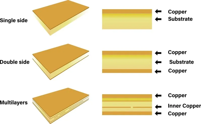
PCB (Printed Circuit Board)
PCB (Printed Circuit Board) is a board that provides a physical platform and electrical connections for electronic components. PCBs are used in various devices such as cell phones, TVs, computers, and many more.
 |
|
|
|
|
Individual Assignment
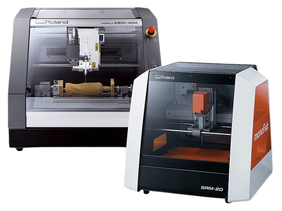
PCB Milling Machine SRM20
Roland MonoFab SRM-20 is a compact and precise desktop CNC milling machine designed for PCB fabrication, prototyping, and small-scale manufacturing. It is widely used in electronics production, engineering, and education for milling PCBs, plastic, and soft metals.
 |
|
|
|
|
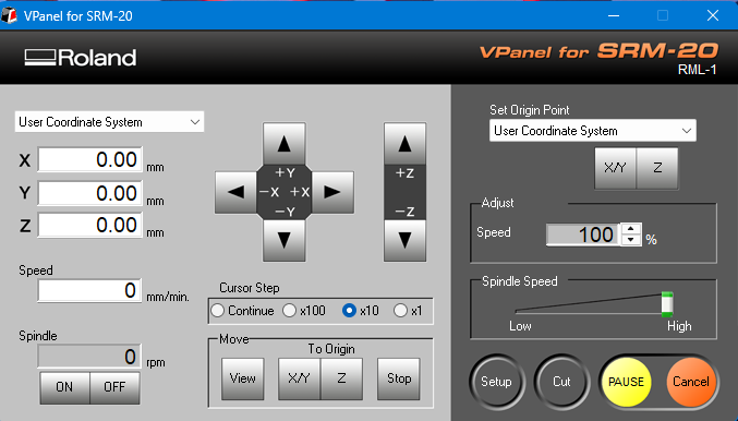
V Panel Software for Operate PCB Milling machine SRM20
VPanel (Virtual Panel) is the control software used for operating the Roland MonoFab SRM-20 CNC milling machine. It provides a user-friendly interface to manage and control the milling process.
 |
|
|
|
|
MODS CE
"Mods CE" is an online platform used for generating toolpaths from "SVG files" for PCB milling and other fabrication processes. It allows users to convert design files into machine-readable formats, ensuring precise cutting and engraving.
 |
|
|
|
|
Microntroller
I selected the XAO ESP32-C3 module to design my microcontroller because it comes with built-in Bluetooth and WiFi. Additionally, its pinout is easy to understand.
Components Used
Generating toolpaths using MODS CE.
Toolpaths for Trace file
 |
 |
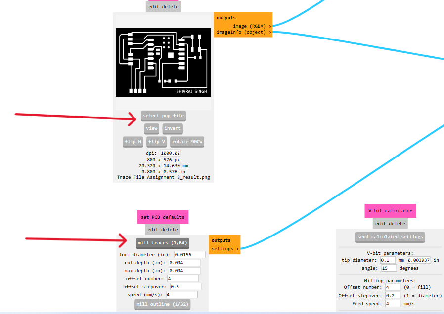
| Open Mods and select PNG file and load it. Once the file is loaded, it will be visible on the interface. |
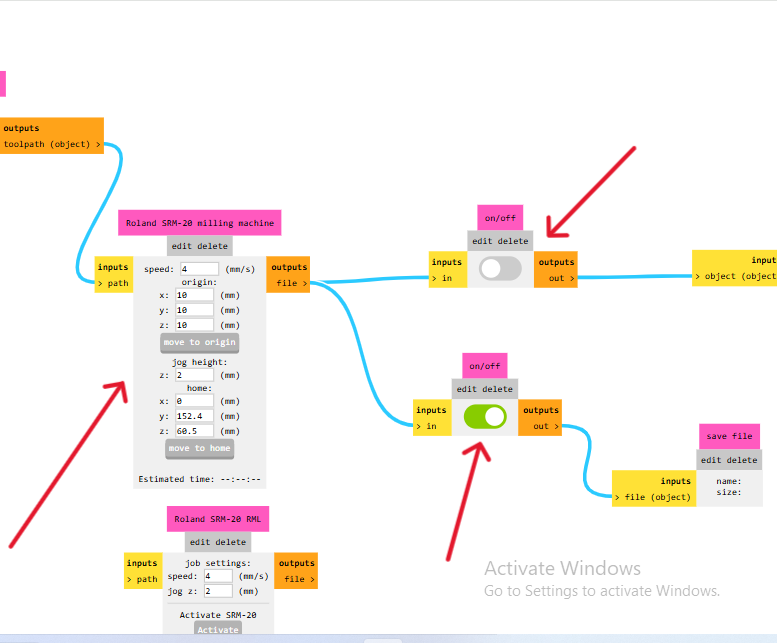
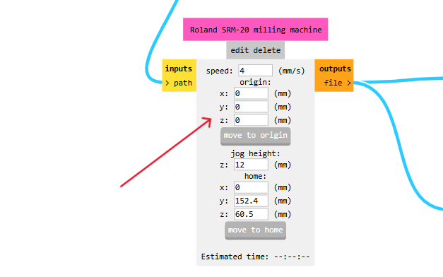
Now, set the XYZ origin to 0, as the machine will be operated through V Panel software. Adjust the settings accurately as per the reference in the provided image. |
 |
 |
| X, Y, and Z axes are set |
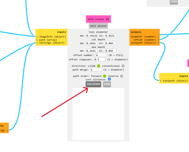
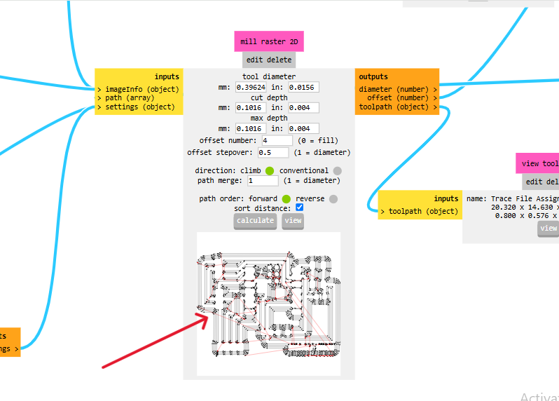
After completing all the settings, click on Calculate to proceed. |
 |
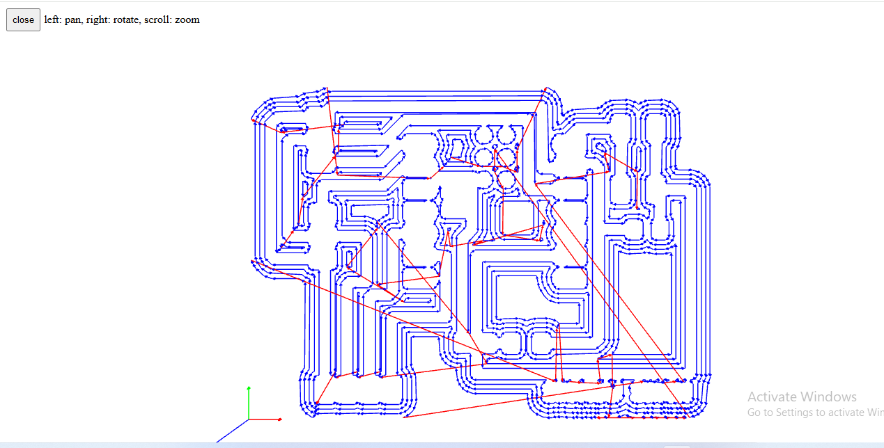 |
| After the calculation, the trace cut file will be generated, and a .rml file will be automatically downloaded. To view the trace cut file, click on the "View" option. |
Trace cut file view |
Use the same process to generate the toolpath for the edge cut file.
Generating G - Code using V panel software.
 |
 |
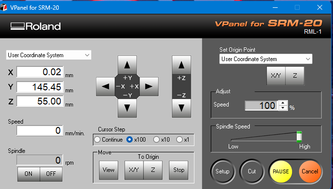
| First, open the V-Panel software. |
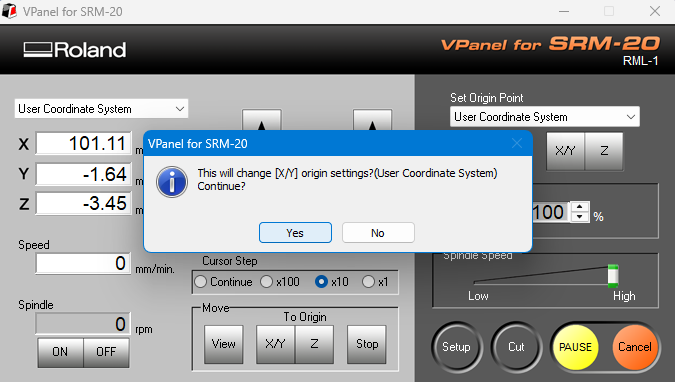
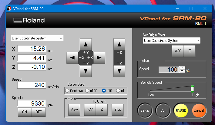
Setting the machine's origin point. |
 |
 |
| Now, the machine's XYZ origin has been successfully set. |
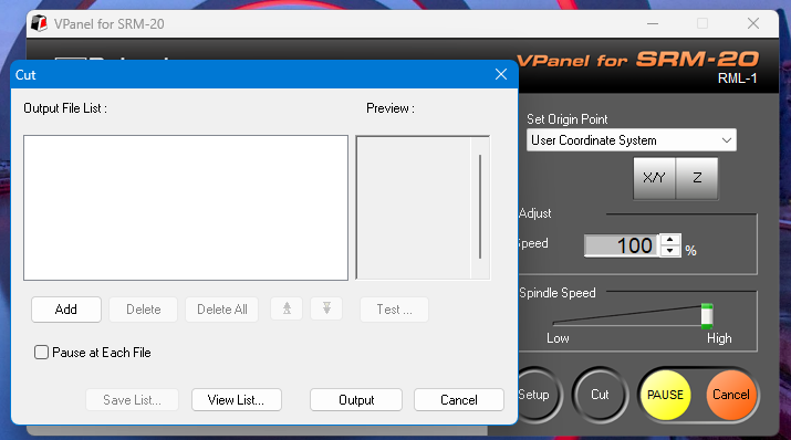
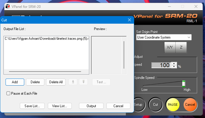
click on the Cut option and load the file. |
 |
 |
| After that, the file has been successfully loaded. Click on the "Output" option to start the cutting process. |
Now, the milling machine has started operating. |
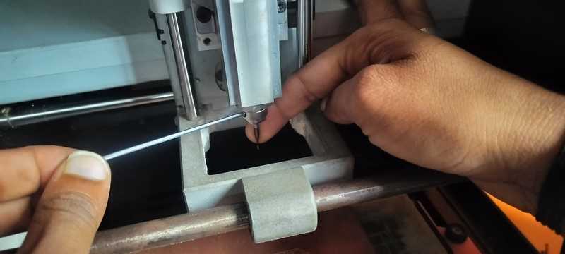
Setting up the milling process and starting the cutting operation.
 |
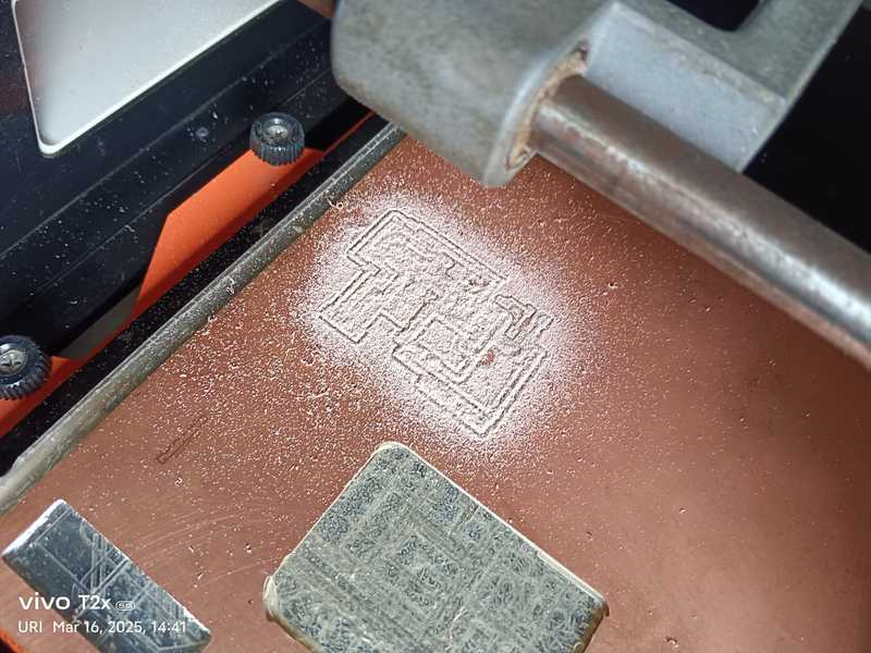 |
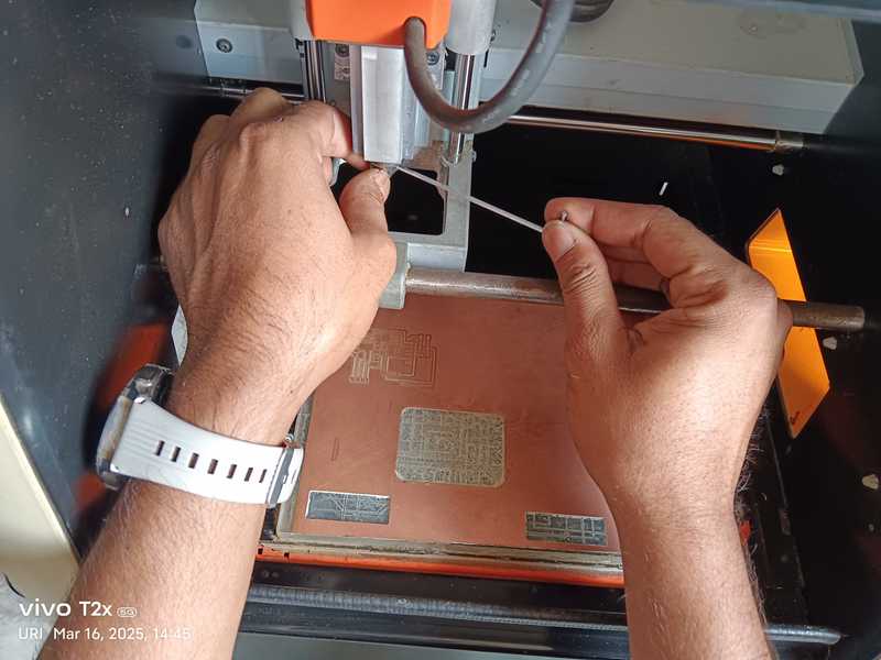
| Inserting the 1/64 bit for tracing and started PCB milling machine |
Trace cut file cutting completed. |
 |
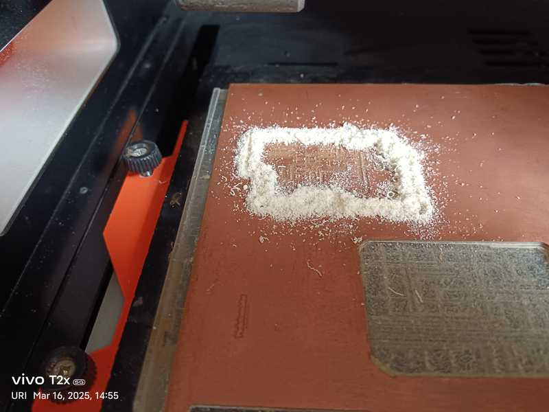 |
| Replacing the bit with 1/32 for edge cutting and started PCB milling machine |
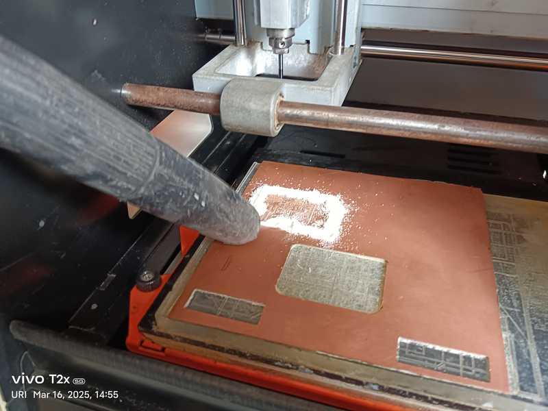
Edge cut file cutting completed. |
 |
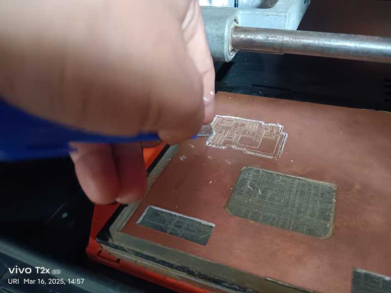 |
| Cleaning the cut PCB with a vacuum cleaner. |
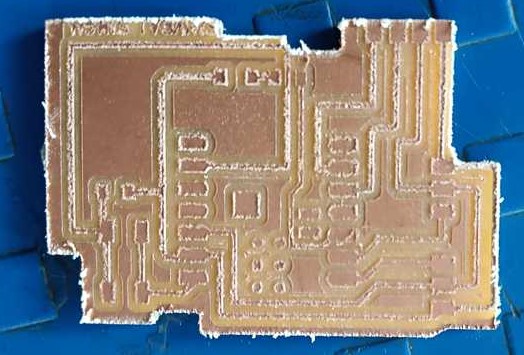
Safely removing the cut PCB from the machine. |
 |
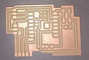 |
| Safely removed the PCB. |
Properly cleaned the PCB, inspected the traces for any cuts, and checked the size. |
| A short video of the PCB during cutting process. |
|
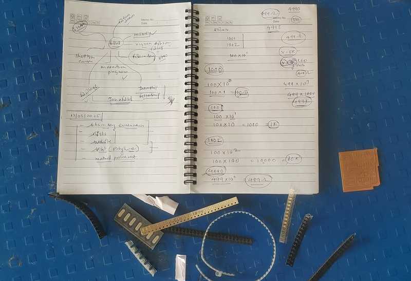
Understanding how the components function.
 |
 |
|
|
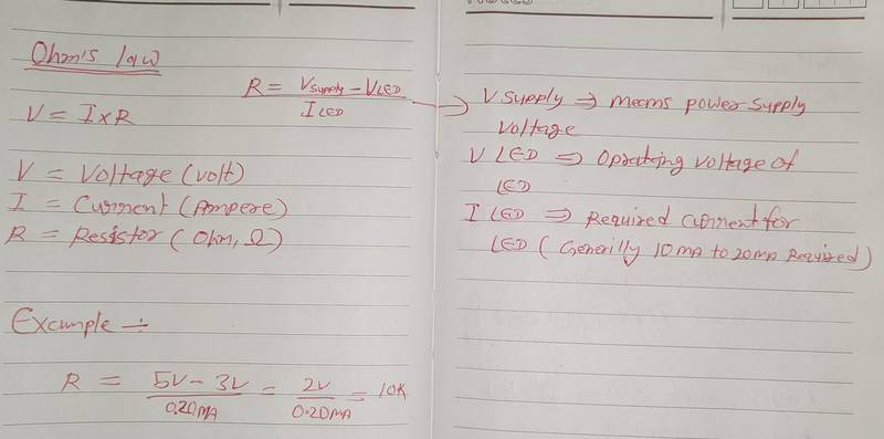
Ohm's formula for calculating resistance |
Components used in PCB and their work
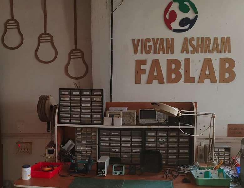
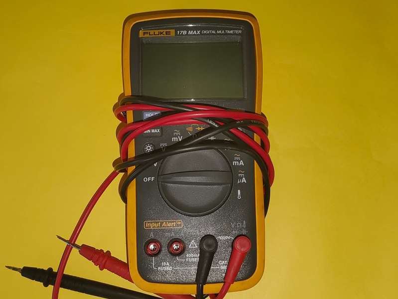
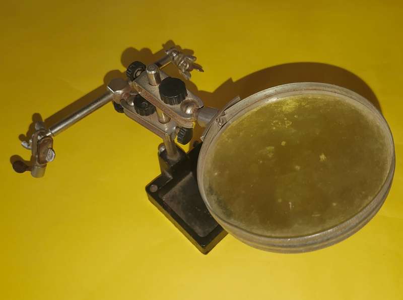
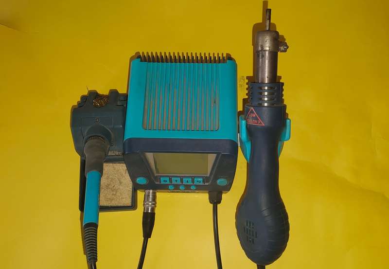
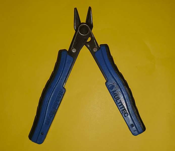
Equipment for Component's assembly and soldering
 |
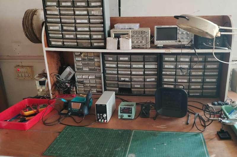 |
| Soldering Station |
|
 |
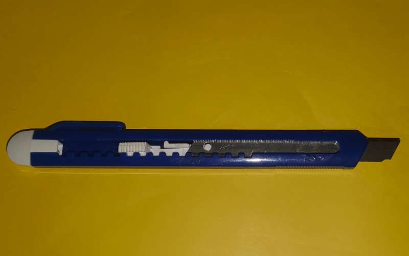 |
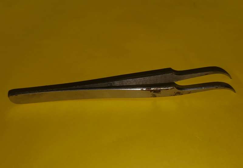 |
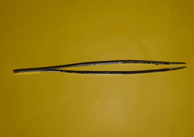 |
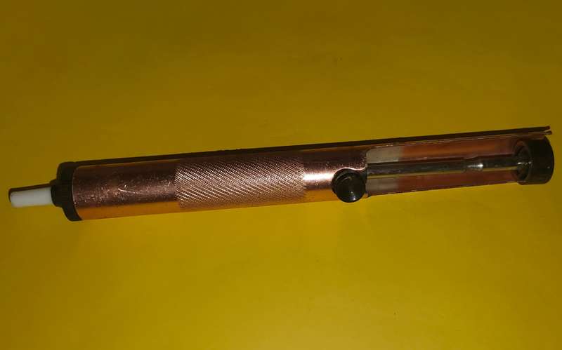 |
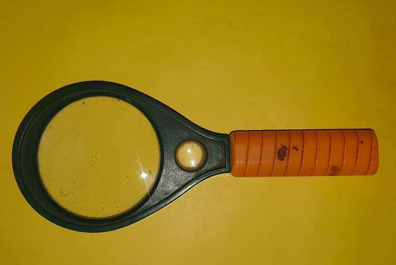
| Magnifying Glass |
Knife |
Curved Precision Tweezer |
Straight Precision Tweezer |
De-Soldering Pump |
 |
 |
 |
 |
 |
| Multimeter |
PCB Holder Magnifying Glass |
soldring iron |
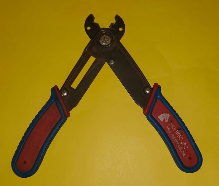
Wire Cutter |
Wire Stripper |
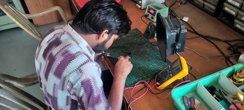
Components Soldering
 |
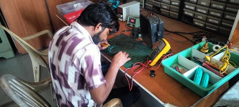 |
| Component's assembly and soldering. |
|
 |
|
| Final Microntroller Complete |
|
Programming the microcontroller.
%20Assignment%208_result.jpg) |
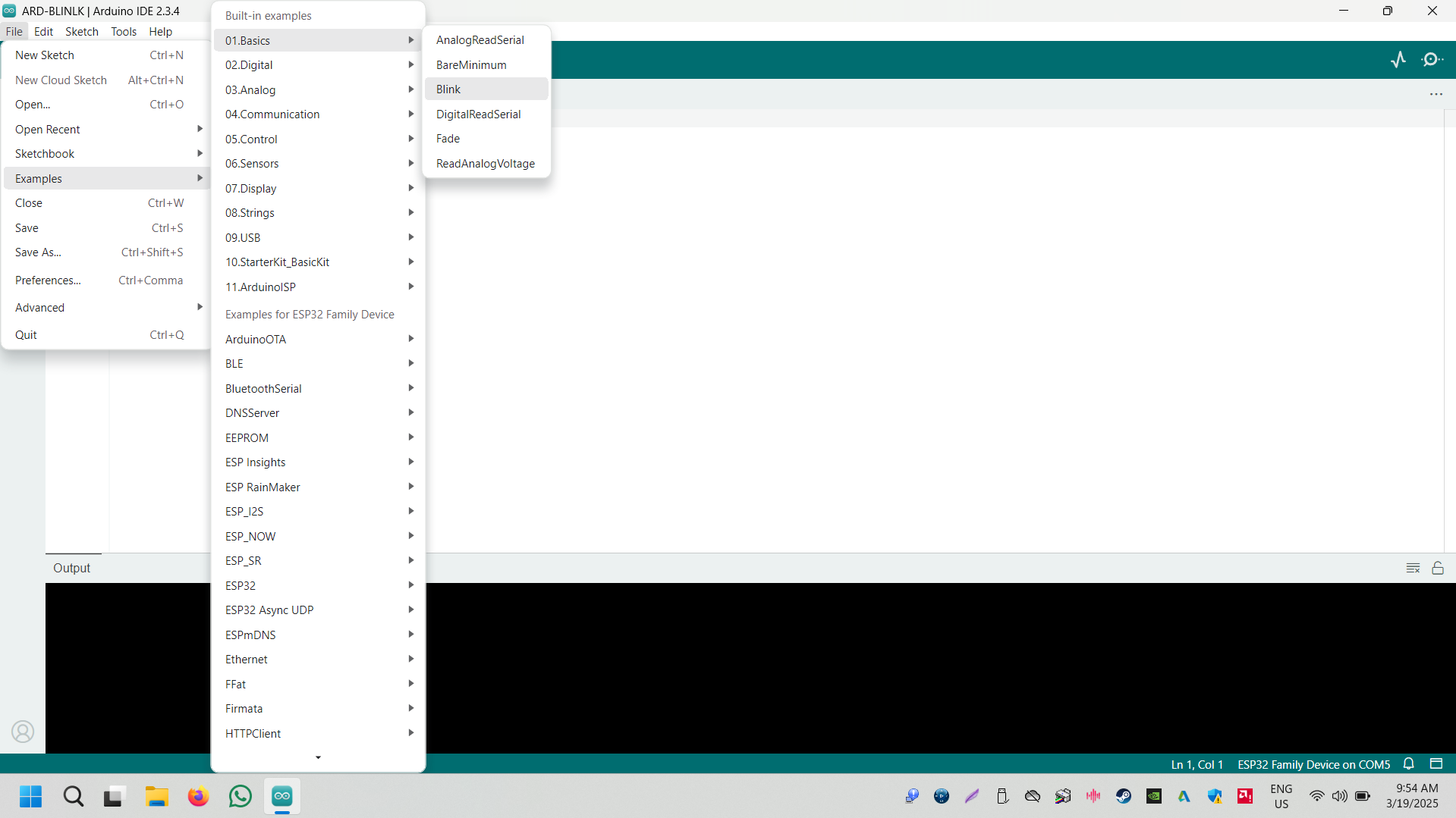 |
| First, connect the Microntroller board to the device. |
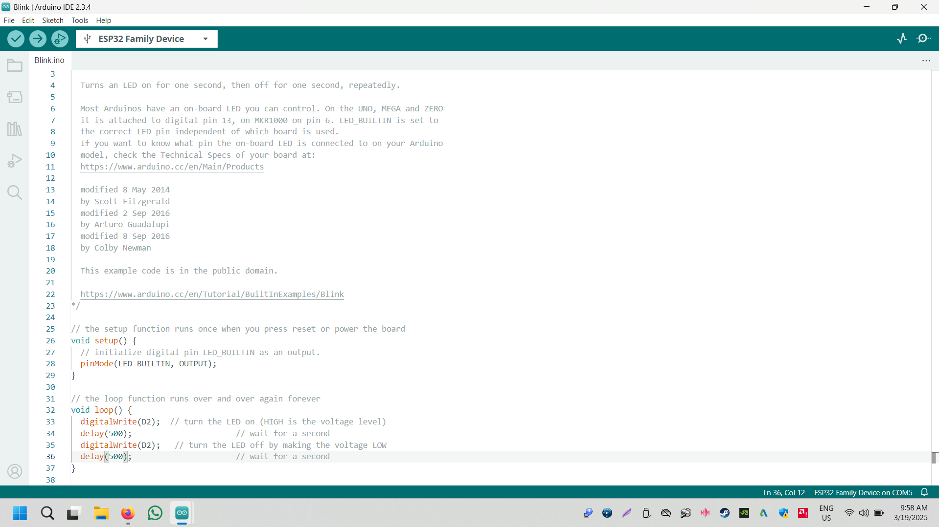
Now, go to the 'File' menu, select the 'Examples' option, click on 'Basics,' and choose 'Blink |
 |
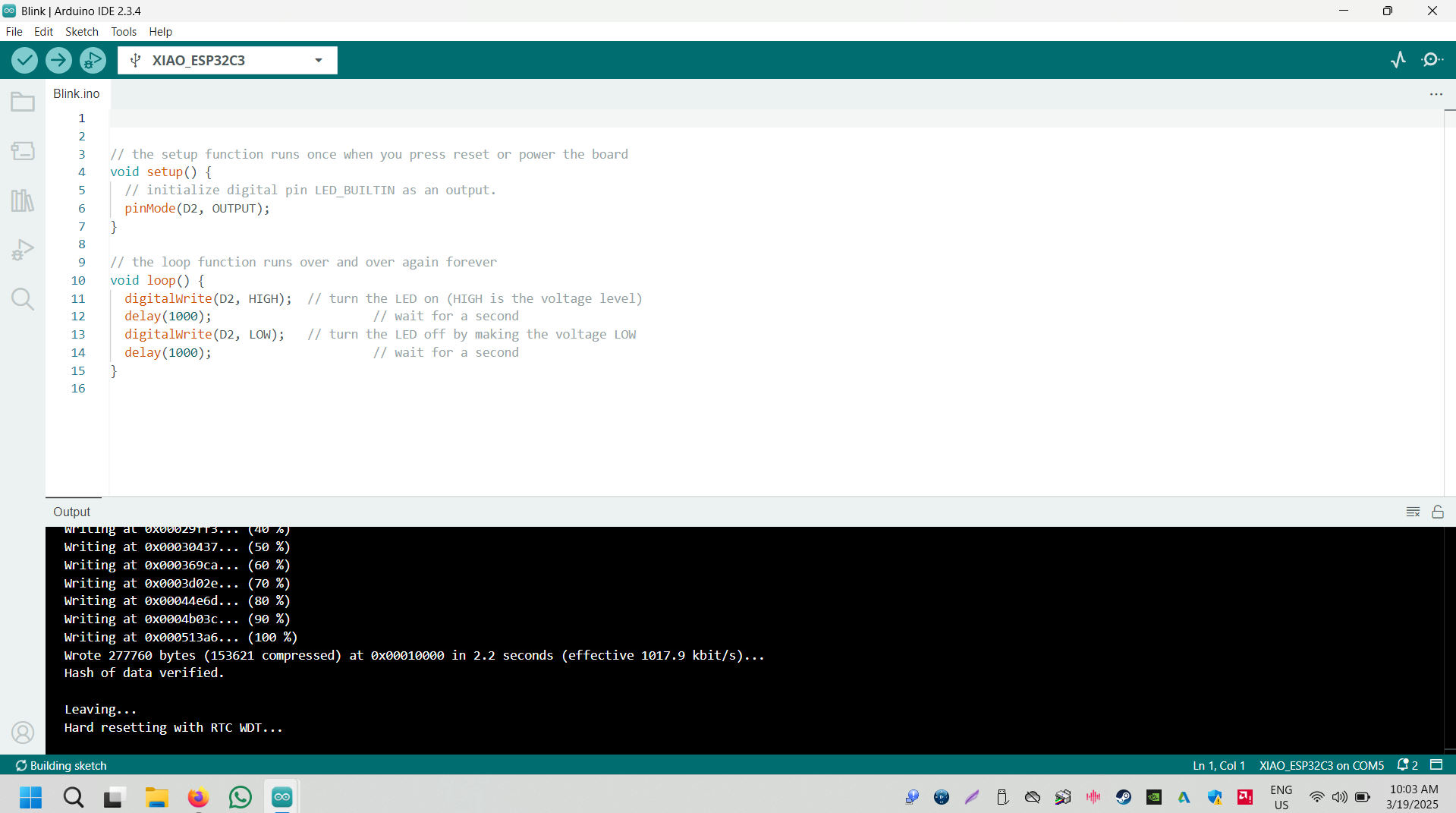 |
| After clicking on the 'Blink' option, the LED blinking code will open now update the code as pr microntroller board pinout |
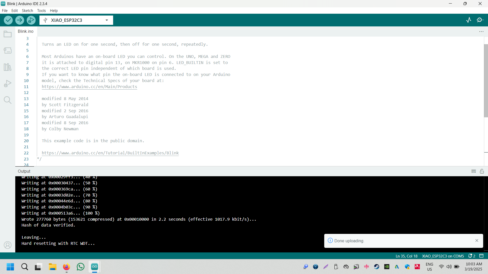
Upload the code |
 |
|
| Code uploading finished |
Now the LED started blinking |
Original File Here
In .rml Formet
Trace File here
Edge Cut File here
In PNG Formet
Trace File here
Edge Cut File here
Conclusion
This week, we successfully milled our microcontroller PCB using a PCB milling machine. After cutting, we thoroughly checked the trace connectivity to ensure proper circuit flow.
Once the connectivity was verified, we proceeded with component placement and soldering. During this process, we also learned about the various components and their functions.
After assembling all the components, we tested the microcontroller to confirm its proper operation. Finally, we programmed the microcontroller and successfully made the LED blink, validating the entire process.
This hands-on experience strengthened our understanding of PCB fabrication, assembly, and microcontroller programming.