
Embedded Programming
Brief Insight of this week
This week of Feb Academy, we learned about programming and how it is used to control devices and equipment. The assignment was divided into group and individual tasks. For the group assignment, the task was to "demonstrate and compare the toolchains and development workflows for various embedded architectures." In the individual assignment, we were required to "browse through the datasheet for our microcontroller, write a program for it, and simulate its operation to interact with local input/output devices and communicate through remote wired or wireless connections." Additionally, there was extra credit available for testing the program on a development board, as well as experimenting with different programming languages and/or development environments.
Objctive of the Assignment
1.Gropu Assignment -
2. Indivisual Assignment -
About Embedded programming
operate hardware devices, such as microcontrollers, sensors, or specialized equipment. Unlike general-purpose computing, embedded systems typically perform specific tasks and are built to operate in real-time environments. These systems often have limited resources, such as processing power, memory, and storage.
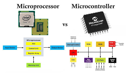
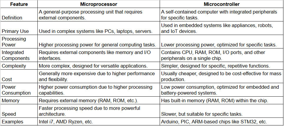
Comprission between Microprocessor and Microcontroller
 |
|
|
|
Microprocessor
Microprocessor is a processing device and is an electronic component that use in various computing systems like as computers, laptops, smartphones, etc.Microcontroller
Microcontroller is a electronic components system, Which have inbuilt memory system and port on one chip. Thats why microcontroller same as a small microcomputer. Basiclly its use in mobile, Camera, Smart watch etc.Comprission sheet
 |
|
|
|
Individual Assignment
Datasheets of the microcontrollers
I read the datasheet a bit and learned about their programs. I understood their connections from their diagrams.
Brif about Microcontrollers
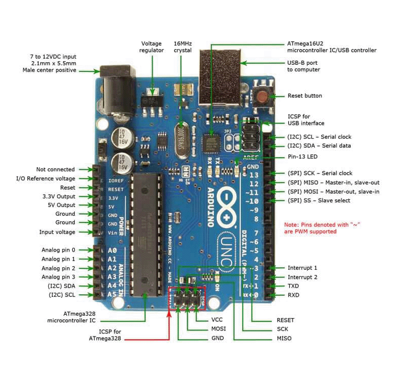
1. Arduino ATMega 328P
The ATmega328P is a microcontroller from Atmel (now part of Microchip Technology), commonly used in many Arduino boards, including the Arduino Uno. It is a versatile, low-power, 8-bit microcontroller that is widely used for embedded systems and DIY electronics projects.
Key Features of Arduino:
I. 23 I/O pins (with 14 digital I/O pins and 6 analog input pins)
II. 6 PWM outputs
III. 1 analog output (via a DAC in some setups)
 |
|
| Pinout Of Arduino |
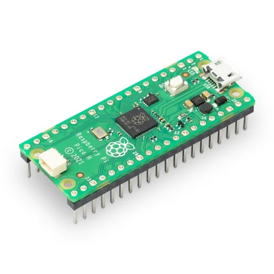
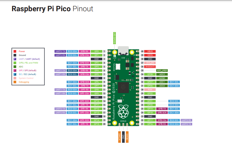
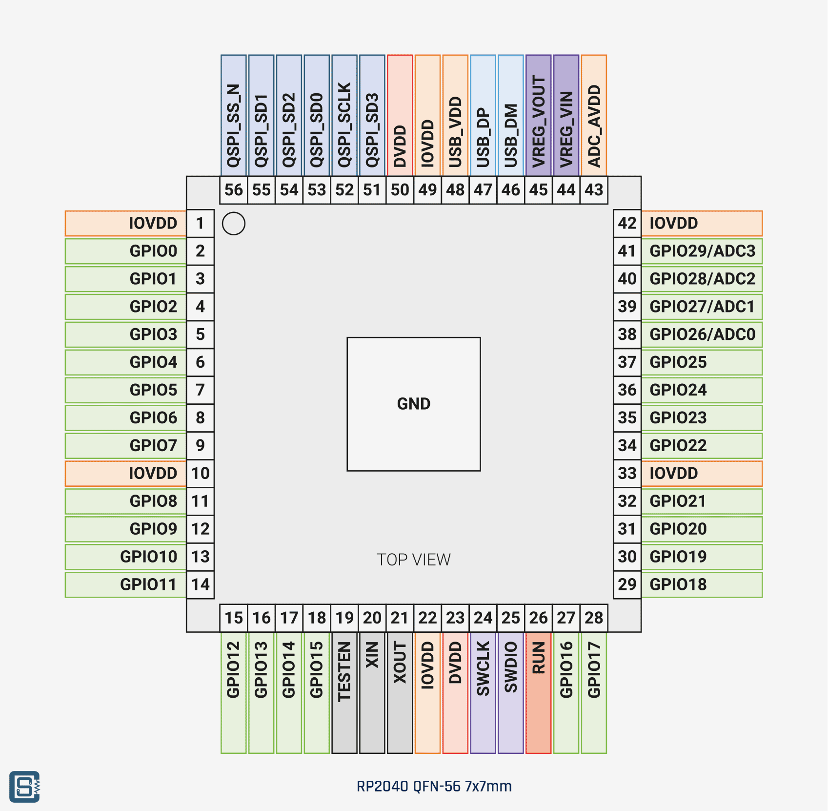
2. Raspberry Pi RP2040
RP2040 is a microcontroller chip developed by the Raspberry Pi Foundation. It is the heart of the Raspberry Pi Pico and other boards built around it. The RP2040 is designed to offer high performance, low power consumption, and flexible I/O options for a wide range of embedded systems applications.
Key Features of RP2040 :
 |
 |
| Front Side |
Pinout Of Raspberry |
 |
|
|
|
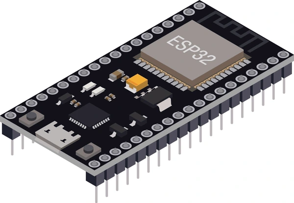
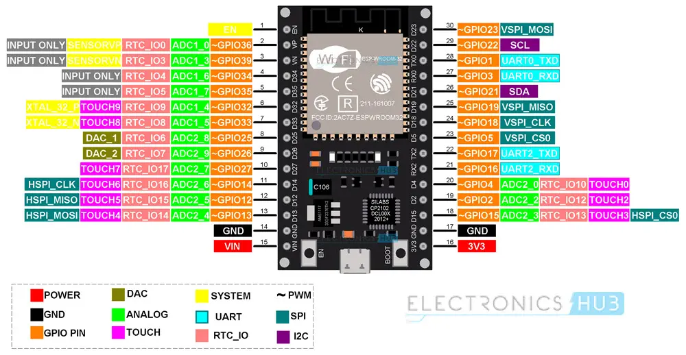
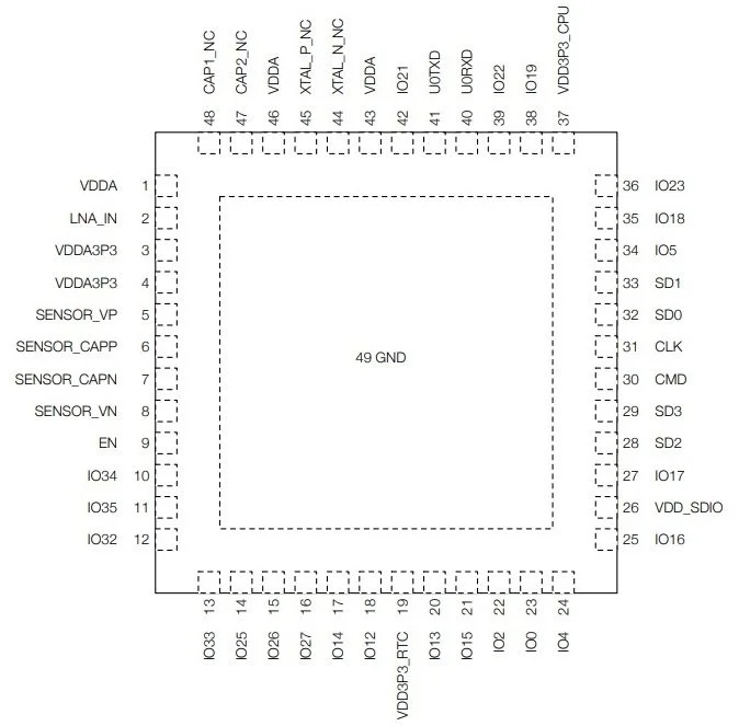
3. ESP32
ESP32 is a powerful and versatile system-on-chip (SoC) developed by Espressif Systems. It is widely used in embedded systems, especially for Internet of Things (IoT) applications, due to its combination of processing power, connectivity options, and low power consumption.
Key Features of ESP32 :
 |
 |
| Front Side |
Pinout |
 |
|
|
|
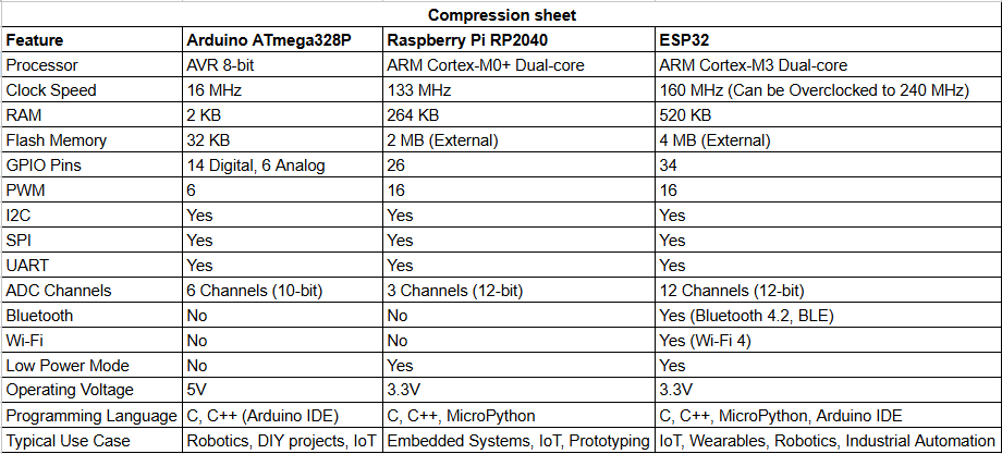
Comparison sheet of microcontrollers
 |
|
|
|
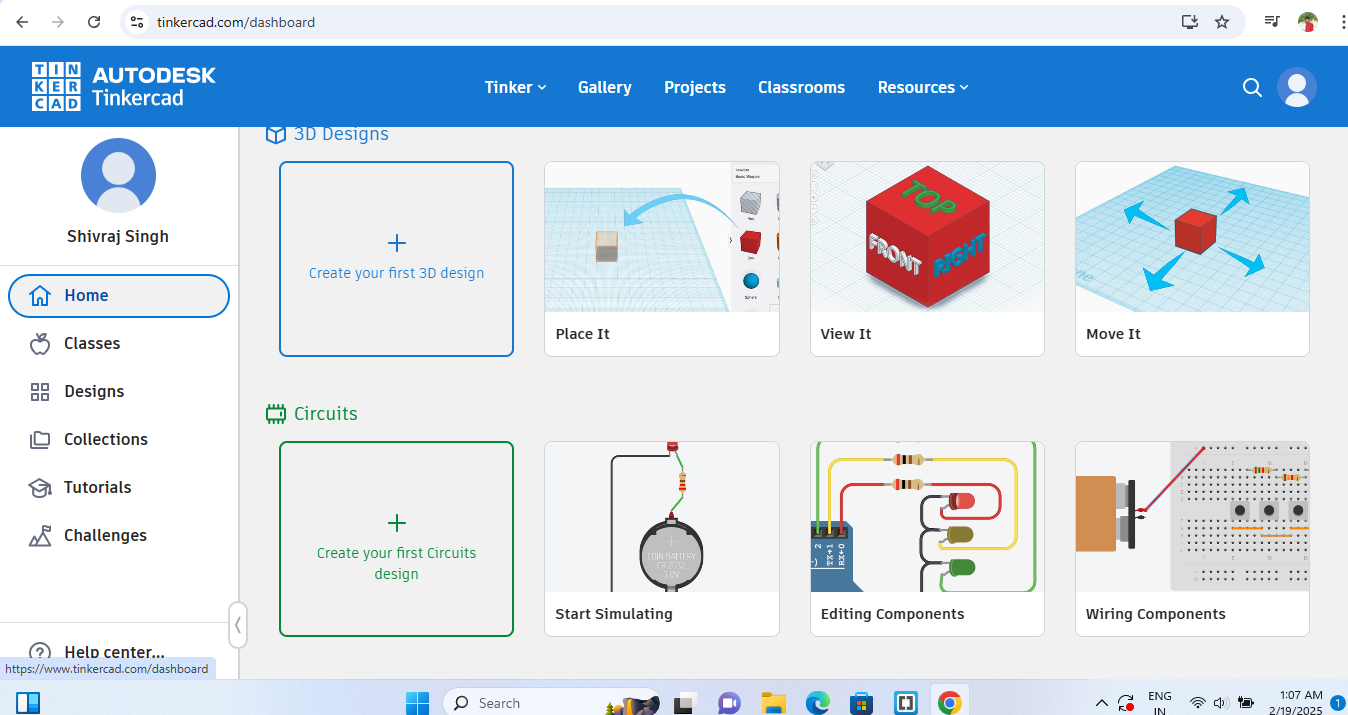
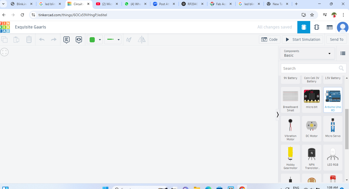
Simulation Process for blinking LED with Arduino in Tinkercad
 |
|
| STEP 1: First open tinkercad and sign up an account, Then select the "Create your first circuit design" from deshboard |
 |
|
| STEP 2: After that, Drop - Down the arduino in work space area |
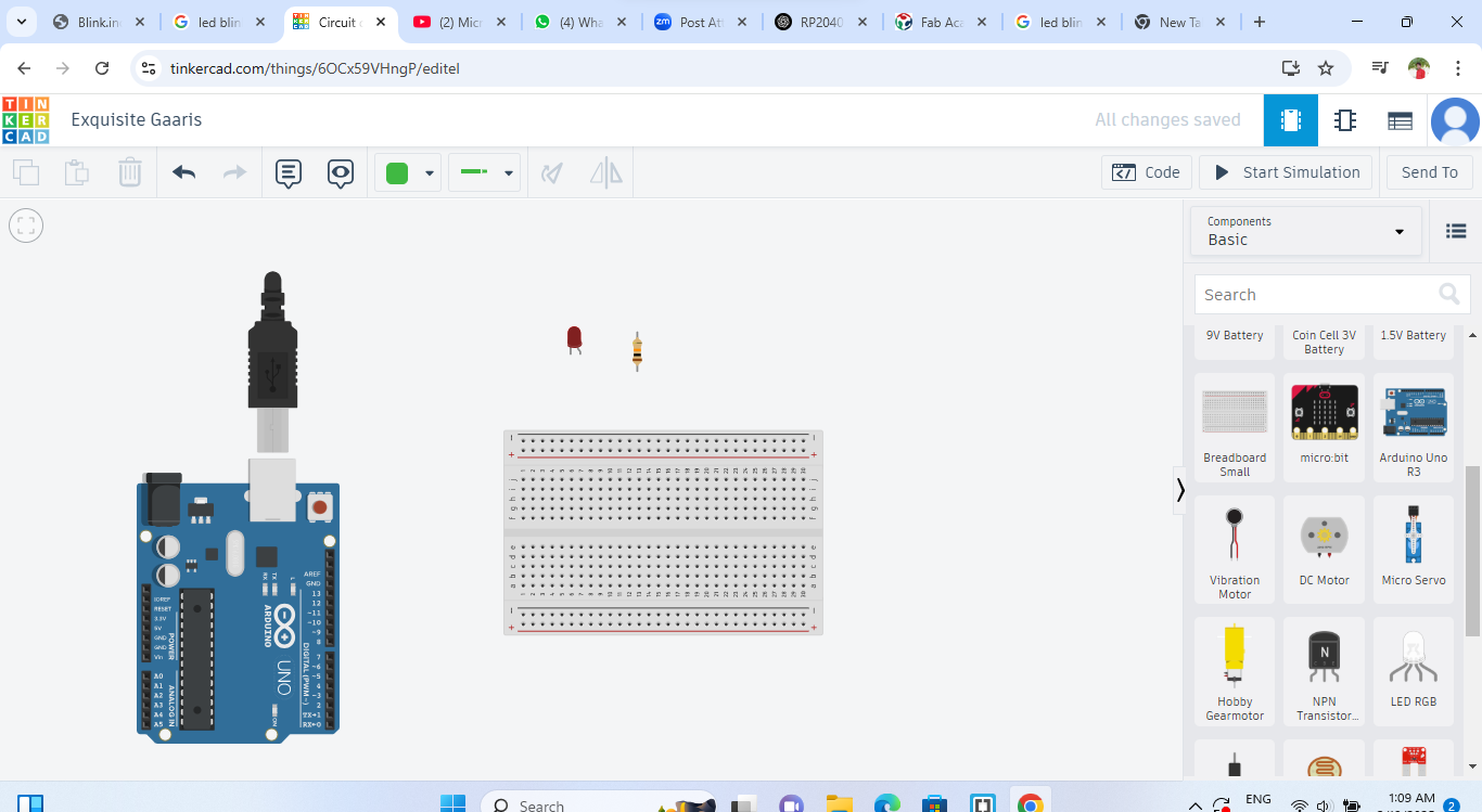 |
|
| STEP 3: Select the component which required for led blinking and drop - down in work space area |
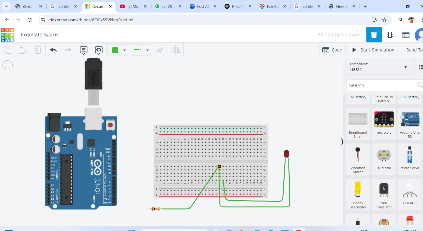 |
|
| STEP 4: Then, Start to make connection |
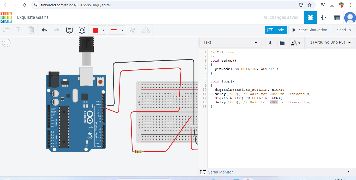 |
|
| STEP 5: After the all connections, Take the blinking code from "Code" section and change it if required. Then start this code to simulation |
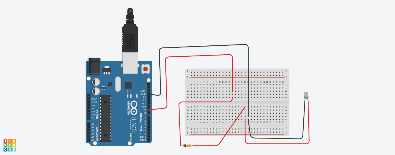 |
|
| STEP 6: After all thease step, LED will start to blinking |
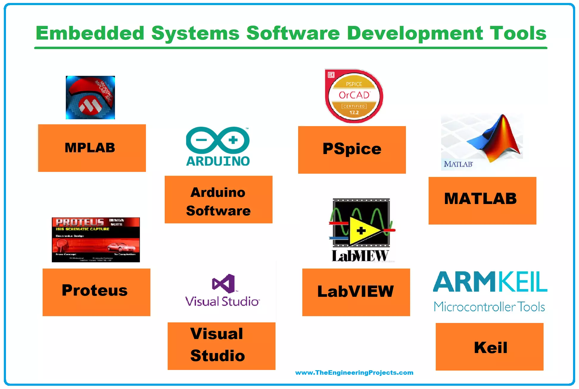
Embedded Software Development Tools
 |
|
|
|
I chose Arduino software because it's easy to operate and offers a wide range of possibilities for projects, making it ideal for both beginners and advanced users.
 |
|
|
|
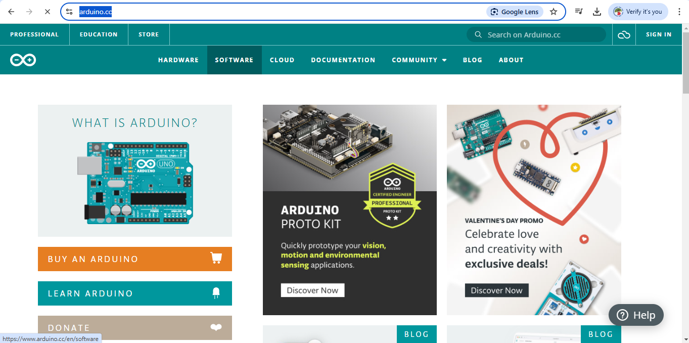
Download and set up process for Arduino
 |
|
| STEP 1: First, visit the official Arduino website and click on the "Software" option. |
 |
|
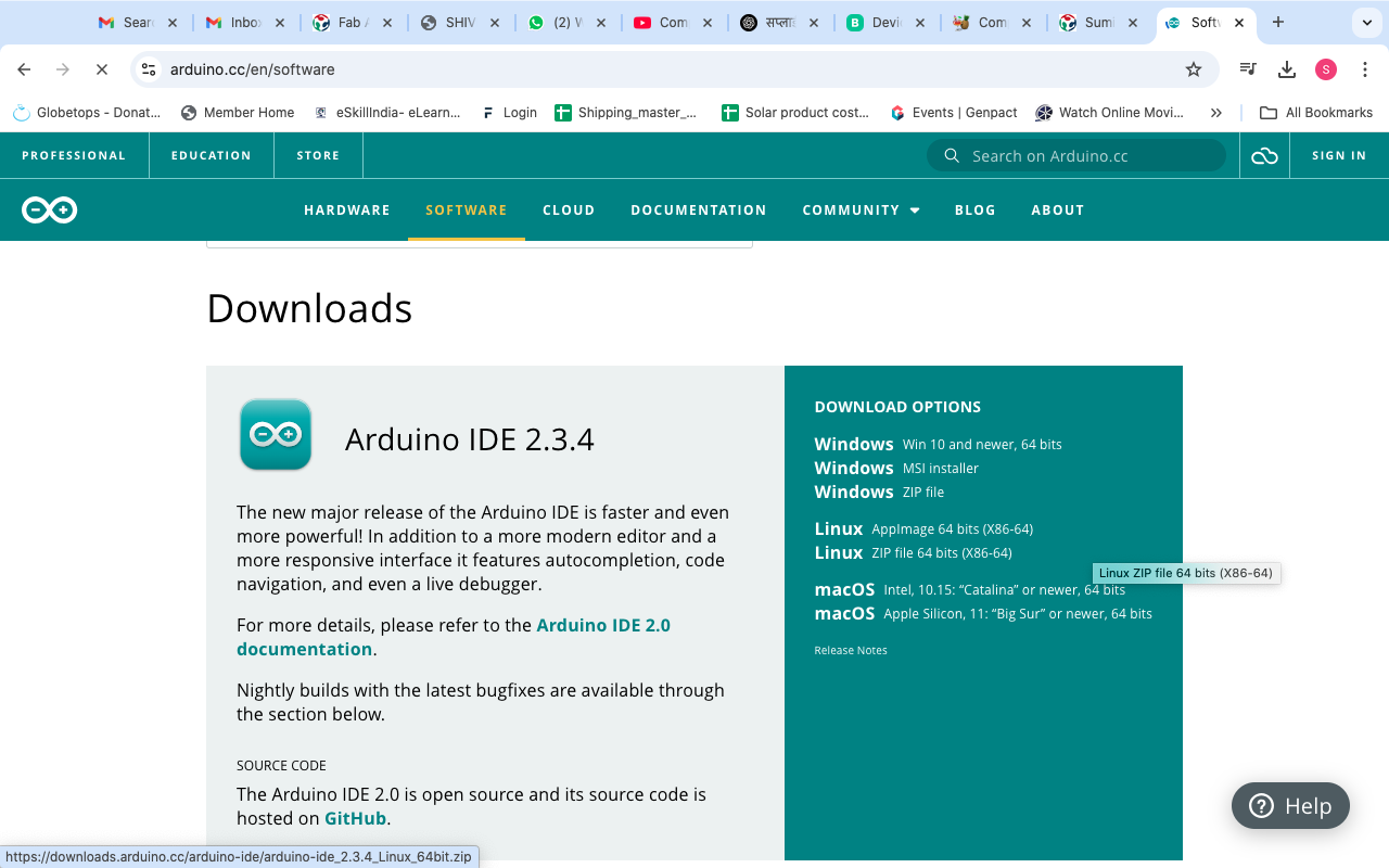
| STEP 2: After that, click on the "Software" option, which will open the download options. Then, you need to click on the "Download" option on the left side. Make sure to select the download link according to the laptop or device you are using |
 |
|
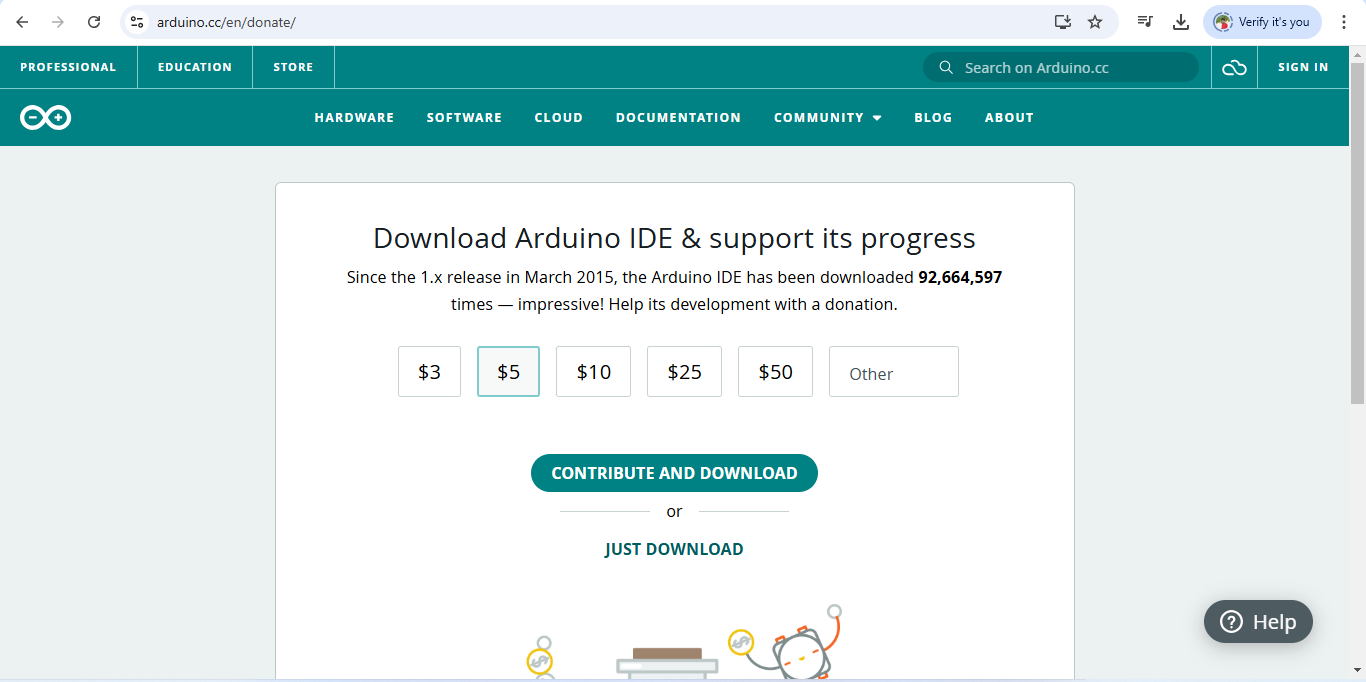
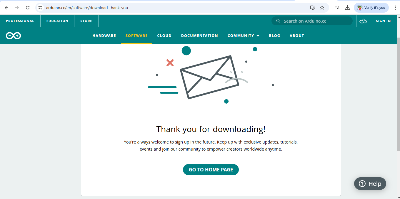
| STEP 3: Now, simply click on the " Just Download" button, and the download will begin |
 |
|
| STEP 4: The Arduino software has been successfully downloaded. You can now install it on your device. |
Programming for blinking LED
 |
|
|
|
 |
|
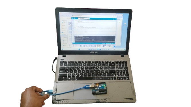
| STEP 1: First, connect the Arduino to the device using USB cable |
 |
|
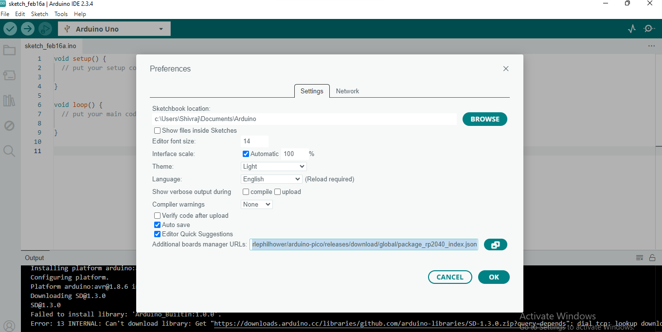
| STEP 2: Next, go to the 'File' menu, select 'Preferences,' and then copy and paste this link: "https://github.com/earlephilhower/arduinopico/releases/download/global/package_rp2040_index.json" in the Additional Board Manager URL field. | >
 |
|
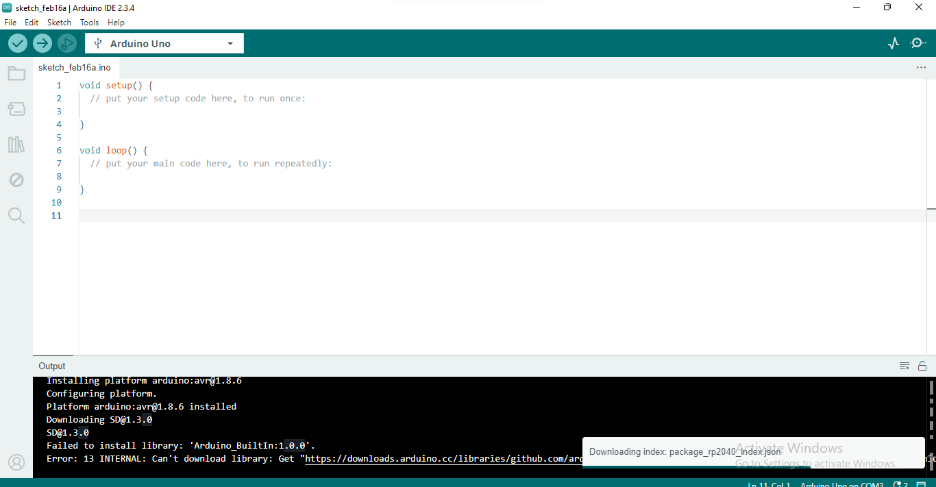
| STEP 3: After this, the index package installation will begin |
 |
|
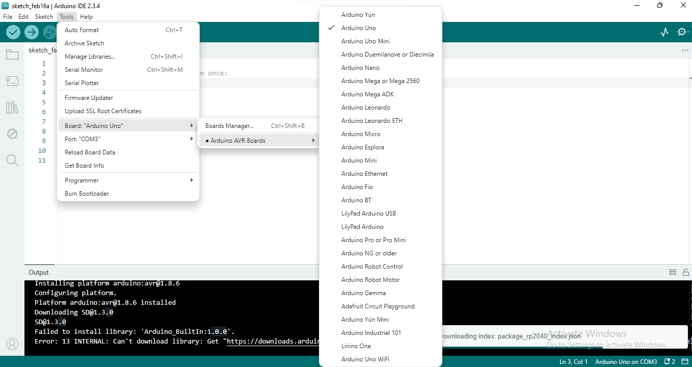
| STEP 4: Next, go to the 'Tools' menu, select the 'Board' option, and choose your Arduino. |
 |
|
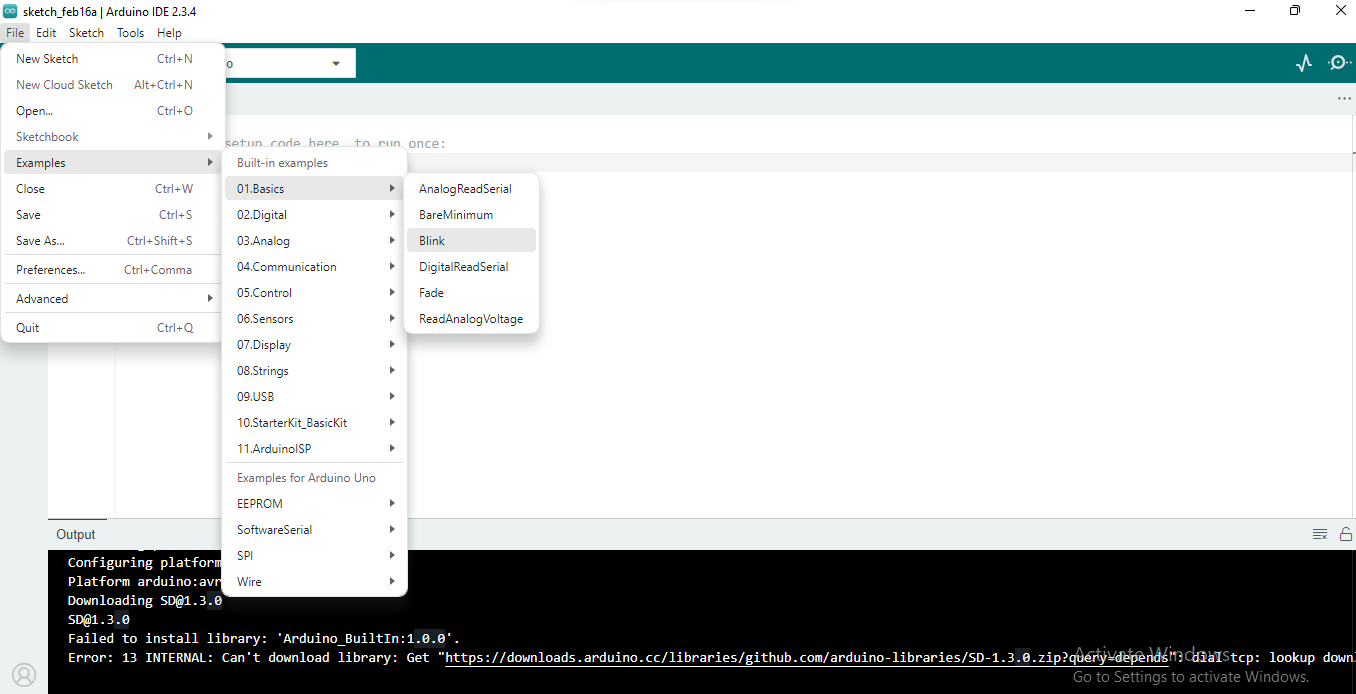
| STEP 5: Now, go to the 'File' menu, select the 'Examples' option, click on 'Basics,' and choose 'Blink |
 |
|
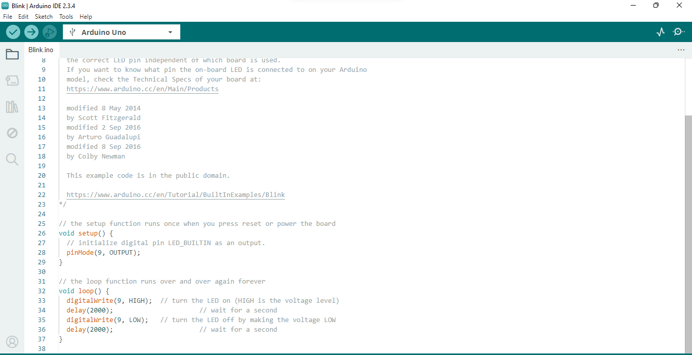
| STEP 6: After clicking on the 'Blink' option, the LED blinking code will open, which you now need to upload to the Arduino. |
| STEP 7: After completing all these steps, the LED blinking will finally begin. |
Exploring Altrasonic sensor with Arduino
 |
|
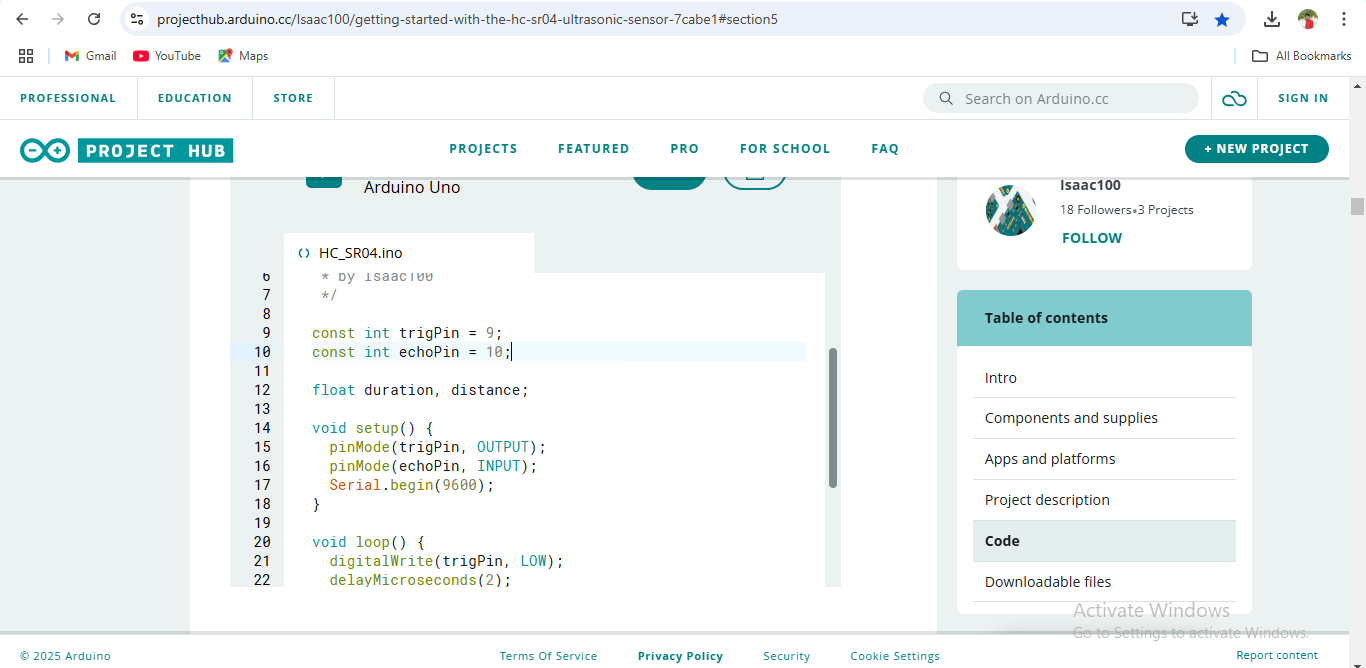
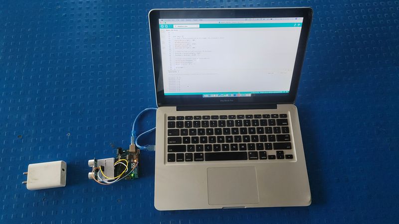
| STEP 1: First, I copied the distance code for the ultrasonic sensor from the "projecthub.arduino.cc" website. |
 |
|
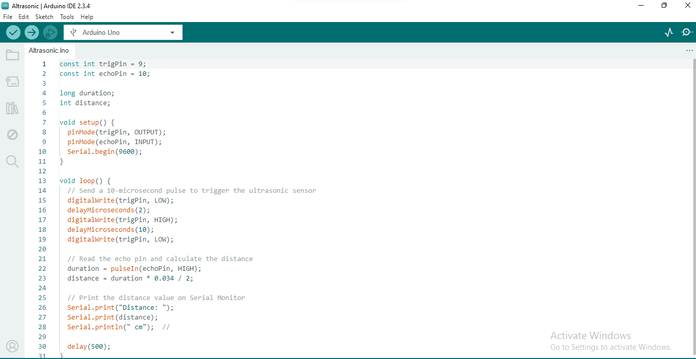
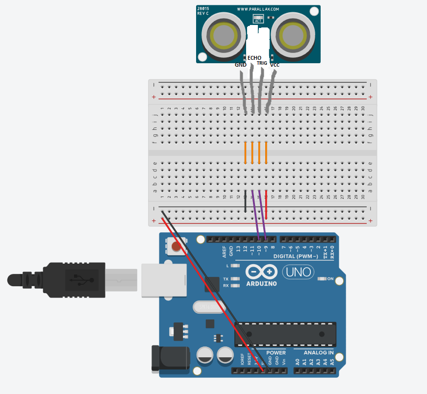
| STEP 2: Then, I putted the ultrasonic sensor to the Arduino and connected the Arduino to the device. |
 |
|
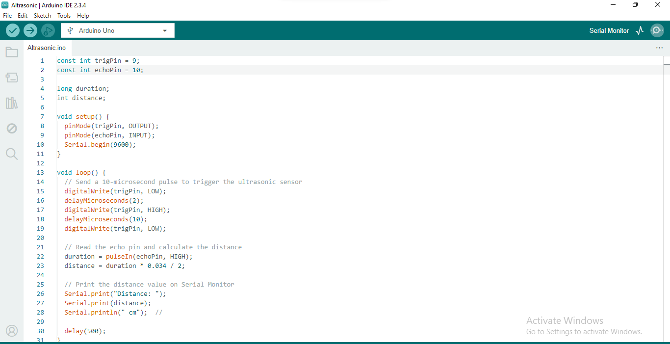
| STEP 3: After that, I pasted the copied code into the Arduino and uploaded it. |
 |
|
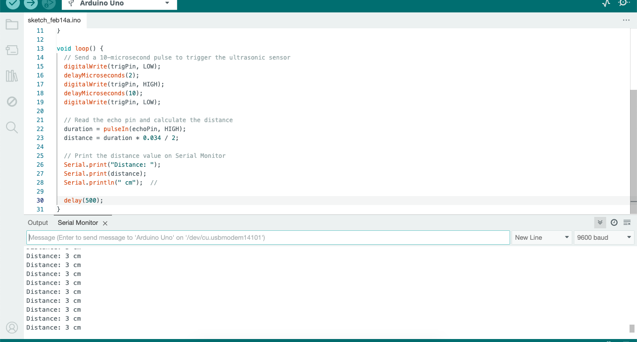
| STEP 4: After uploading the code, I clicked on the "Serial Monitor" option to view the output. |
 |
|
| STEP 5: Finally, the distance reading started displaying, and the data was received. |
 |
|
| Diagram |
Explanation of the Ultrasonic Sensor Code
As I mentioned above, I took the ultrasonic sensor code from the website projecthub.arduino.cc. In addition to that, I also explored and studied the code myself. Below, I am providing a detailed explanation of how the code works.
const int trigPin = 9;
( Trig pin Connected to arduino pin 9)
const int echoPin = 10;
( echo pin connected to arduino pin 10)
long duration;
( For masure eco signal)
int distance;
( To store distance in centimeter)
void setup() {
pinMode(trigPin, OUTPUT);
( Trig pin set as in output mode)
pinMode(echoPin, INPUT);
( echo pin set as in input mode)
Serial.begin(9600);
( started serial moniter so we can see the destance ) }
void loop() {
digitalWrite(trigPin, LOW);
( To clear any old signal)
digitalWrite(trigPin, HIGH);
( TrigPin high because sensor can send data like - sound)
delayMicroseconds(10);
digitalWrite(trigPin, LOW);
duration = pulseIn(echoPin, HIGH);
( We can masure the time taken for high signal to come at the echo pin)
distance = duration * 0.034 / 2;
( This is the formula for masureing time, distance)
Serial.print("Distance: ");
( to print distance on serial monitor)
Serial.print(distance);
Serial.println(" cm");
( To print distance in centimeter)
delay(500); }
( 500 delay because sensor can't masure every time)
Download Original File's
LED blinking Code here
Ultrasonic Sensor Distance Code here