
Computer Controlled Cutting
brief Insight of this week
This week, our main task was Computer Controlled Cutting, which included both group and individual tasks. The objective of this assignment was to properly document our work and use machines to print designs. We were required to print parametric designs using the laser cutter and vector designs using the vinyl cutter. Our goal was not only to use these machines correctly but also to document the entire process properly so that this technology can be effectively and accurately used in the future. During this, we also learned how to create a precise balance between design and printing, and we gained knowledge about machine setup, operation, and safety standards.
About Computer Controlled Cutting
Overview: - Computer Controlled Cutting refers to using a computer to operate cutting tools or machines. These machines can cut, shape, or carve materials like metal, wood, plastic, or fabric based on digital designs or instructions. It works by sending commands from a computer to a machine like a CNC (Computer Numerical Control) cutter or laser cutter. The machine then follows the computer’s instructions to make precise cuts with high accuracy, reducing human error. This technology is widely used in manufacturing, engineering, and design.
Group Assignment
Throughout this week, our focus was on laser cutting and scanning technologies. We worked as a team and made an effort to deeply understand both of these techniques. The objective of this task was not only to use these machines correctly but also to comprehend their working principles, setup, and operation. The main objectives of this task were as follows:
Individual Assignment
Parametric Design in Fusion 360
 |
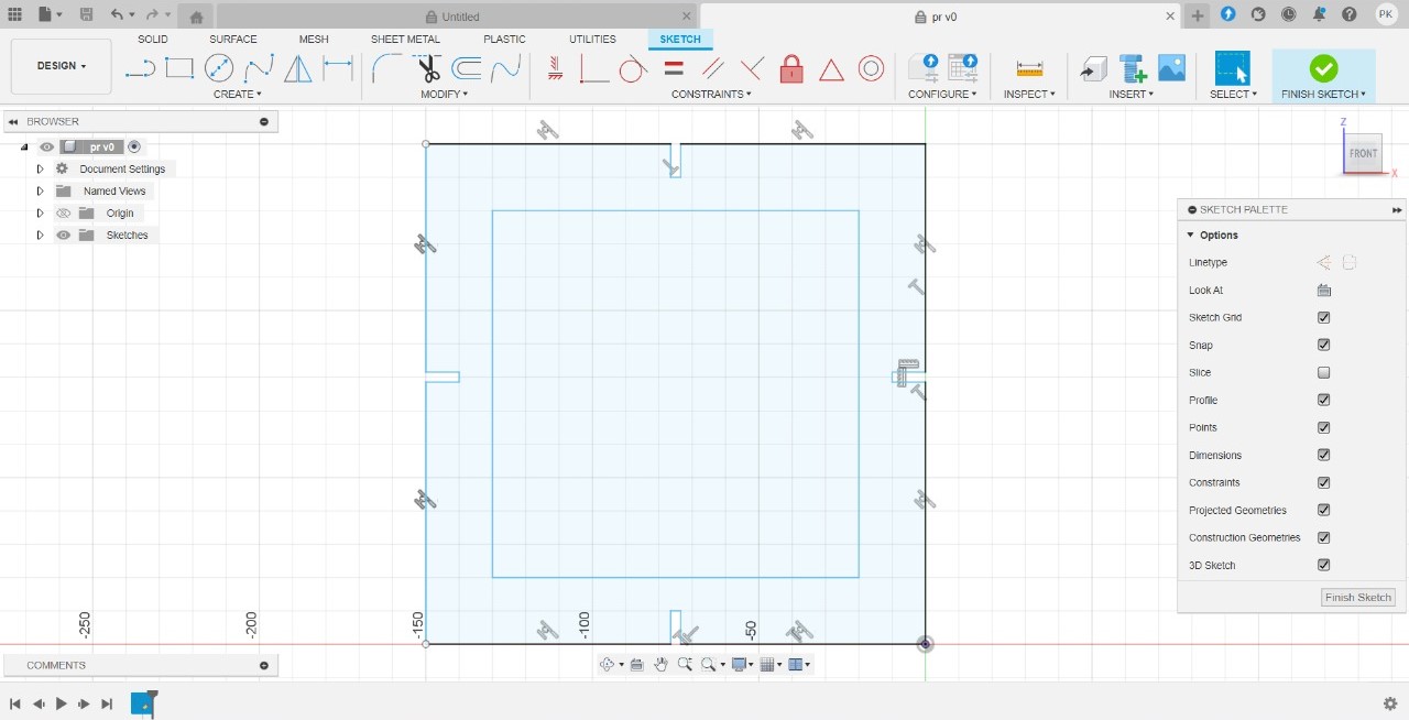 |
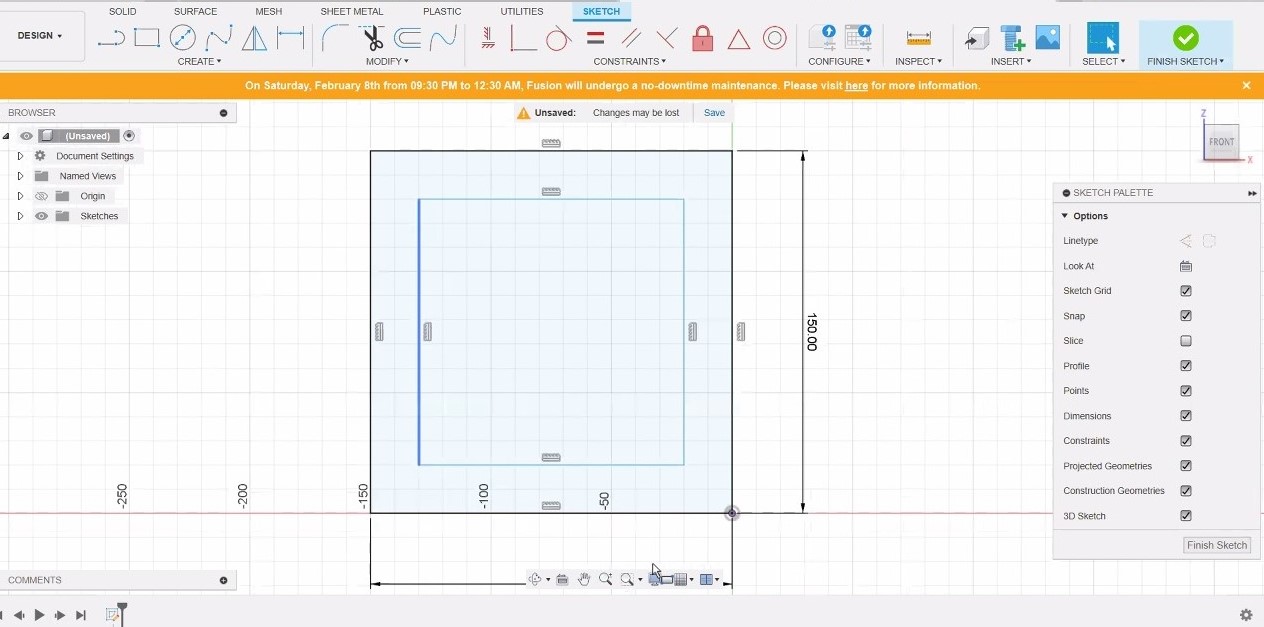
| STEP 1: Make a rectangle with dimensions 150 mm by 120 mm. |
STEP 2: A rectangle was made for the press feet with a width of 3 mm and a height of 10 mm, then trimmed to form four corners. |
 |
 |
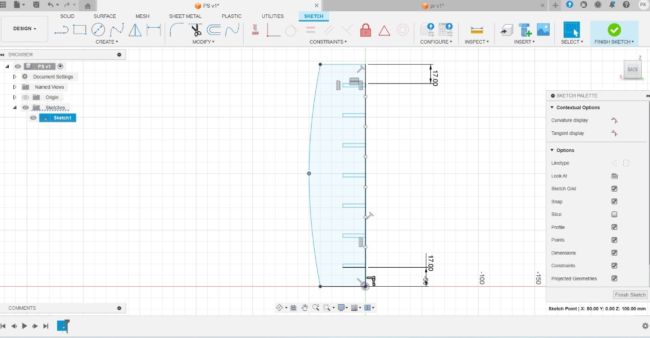
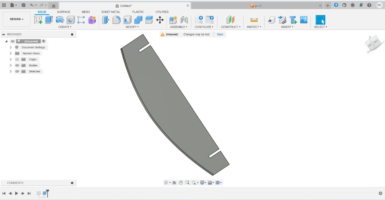
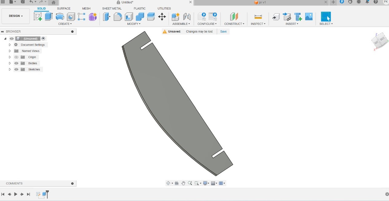
| STEP 3: A 200 mm rectangle was created, and a round shape was applied to the top. |
STEP 4: Then, a rectangle was created again for the press fit with a width of 3 mm and a height of 10 mm. |
 |
 |
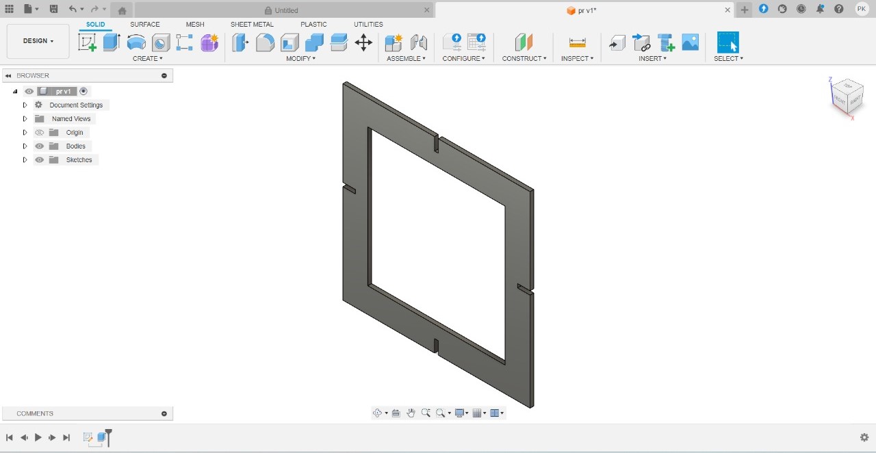
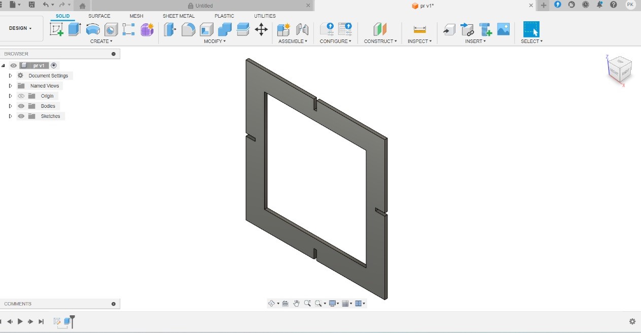
| STEP 5: The first design was extruded using the Boss-Extrude feature. |
STEP 6: Second design was extruded using the Boss-Extrude feature. |
Design Assembling in Fusion 360
 |
 |
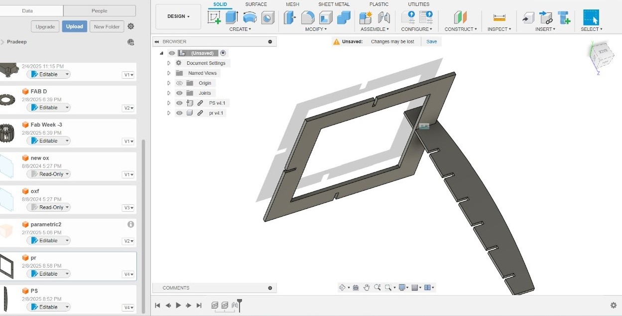
| STEP 1: A new page was created for design assembly, and the design was inserted. |
STEP 2: Eight parts were created for Design 1, and four parts were created for Design 2. |
 |
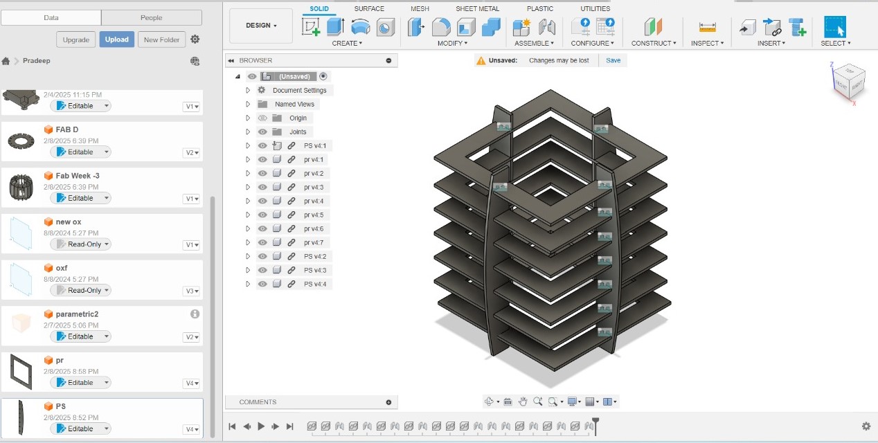 |
| STEP 3: Both designs were assembled together to ensure that they fit properly according to the measurements. |
STEP 4: The final design was assembled. |
Cardboard & Design Size and Kerf Measurement
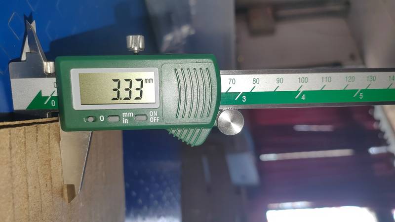
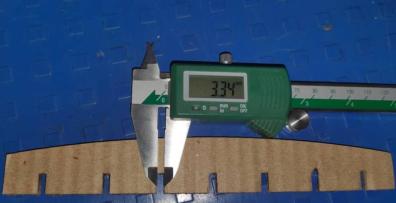
As we had explored in our group assignment during the speed pattern testing, we used a power setting of 70 and a speed of 30 on the laser cutter. This resulted in a clean and accurate cut, and we observed a kerf of 0.30 mm. Following the same pattern, I designed my individual assignment with a material thickness of 3 mm. However, I selected cardboard with an actual thickness of 3.33 mm to compensate for the 0.30 mm kerf expected during the laser cutting process. For my individual work, I again set the laser cutter to 70% power and 30 speed, and then initiated the cutting process.
 |
|
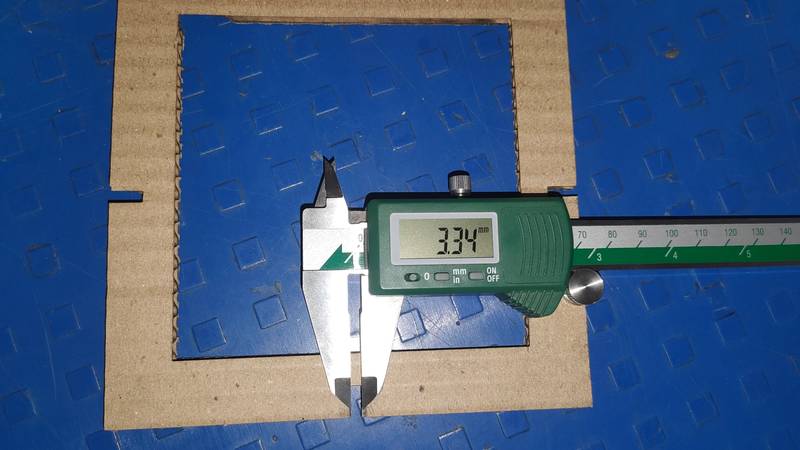
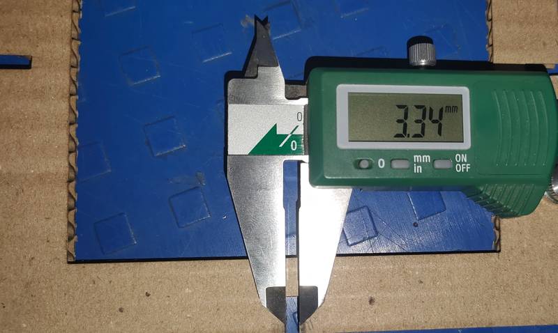
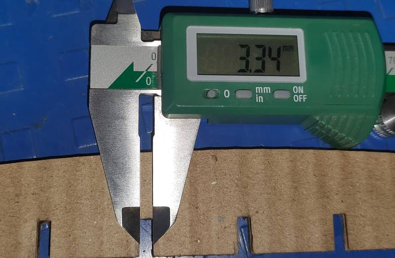
| Cardboard Size is 3.34mm |
Design Size is 3mm |
Kerf Calcuation
After completing the design cutting, I measured the cut section using a Vernier Caliper. Initially, I had designed the part to be 3 mm thick. However, after cutting, the measured thickness was showing 3.34 mm. This confirmed that we had already checked the cardboard thickness beforehand, which was 3.33 mm. Accordingly, I designed it to be 3 mm, taking the expected kerf into account. As you can see in the images below, the kerf appears to be approximately 0.34 mm — slightly more than the expected 0.30 mm.
 |
 |
|
|
|
 |
 |
|
|
|
Cutting and Jointing Together
.jpeg) |
.jpeg) |
| STEP 3: Both designs were assembled together to ensure that they fit properly according to the measurements. |
STEP 4: The final design was assembled. |
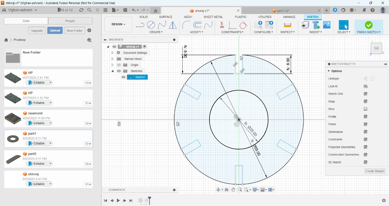
Parametric Design in Fusion 360
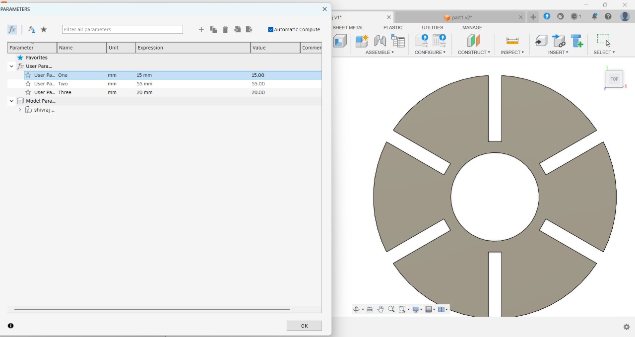
Parametric Design in Fusion 360 allows users to create models where dimensions and features are linked. Changes made to one part of the design automatically update the rest, offering flexibility and efficiency for complex projects. This approach ensures easy modifications and precise control over the design process.
 |
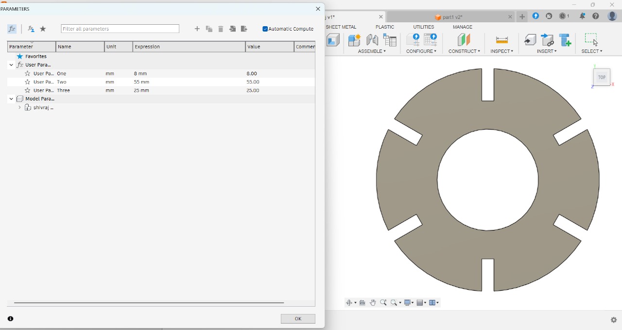 |
| First, a circle with a diameter of 55 mm was created, along with a smaller concentric circle of 25 mm. The dimensions were set using the "Sketch Dimension" tool (shortcut key: D). Then, the sketch was turned into a 3D model using the "Extrude" feature. | After using the Extrude feature, I used "Modify" menu and added user-defined parameters to make the design fully parametric and easily adjustable. |
 |
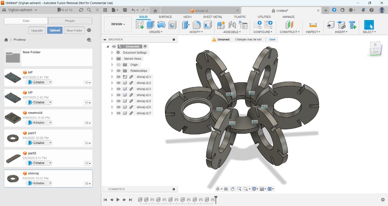 |
| After adding user parameters and assigning them to the dimensions in the design, now whenever I change the value of any user parameter, the entire design automatically updates accordingly. | After that, I assembled the design by arranging all the components together in the correct position. |
| Assembling video |
Vinyl Cutter
Key future of Vinyl Cutter
Understanding the Operation and Specifications of Vinyl cutter
 |
|
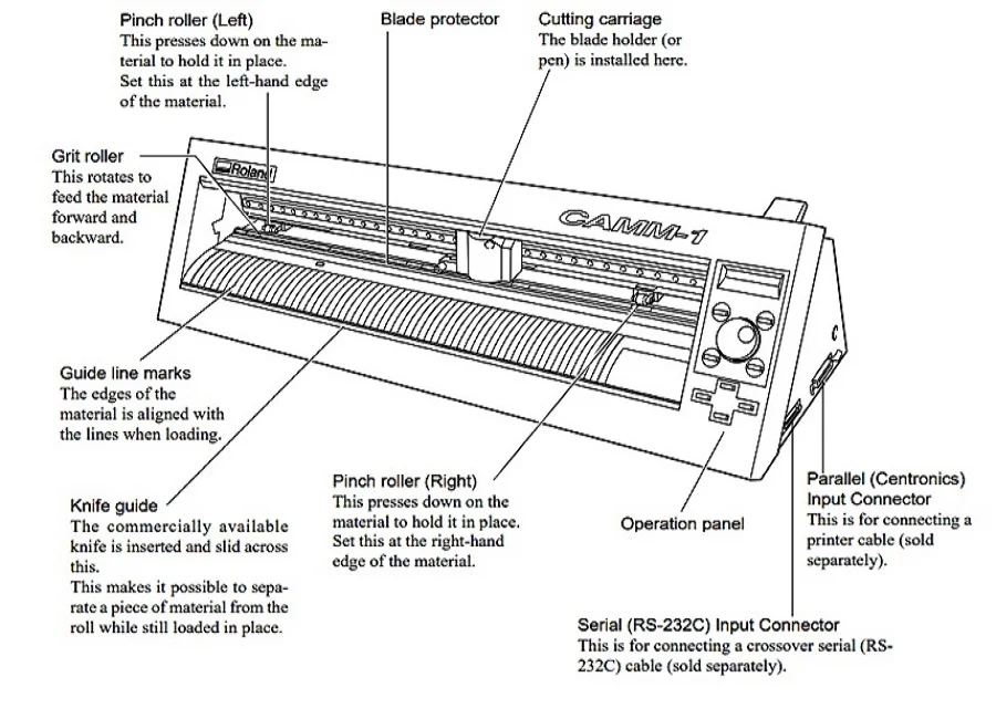
| Understanding the Operation of Vinyl cutter |
|
 |
|
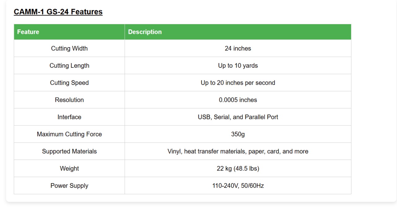
| Specifications Sheet |
|
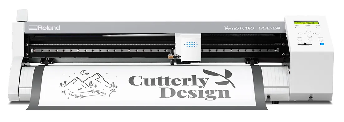 |
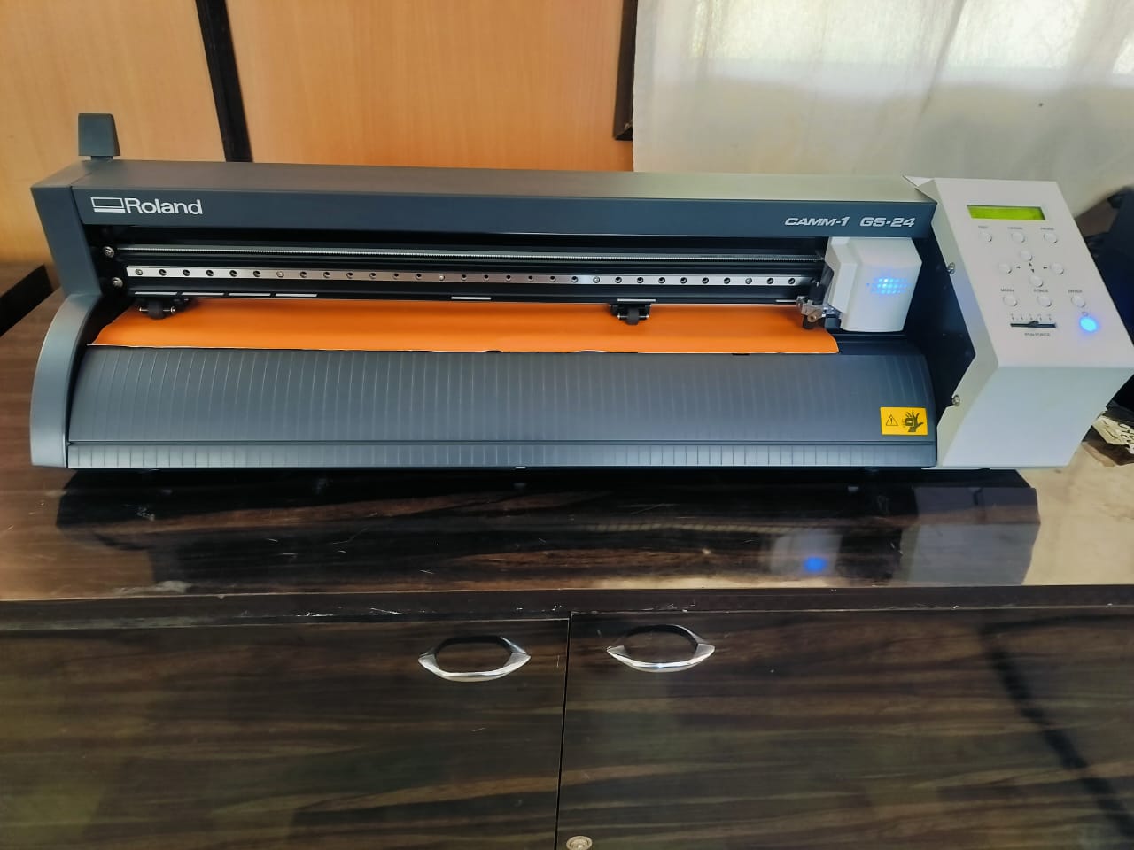
| Roland - VersaSTUDIO GS2-24 Vinyl cutter |
Vinyl Plotter Design, Creation and Cutting Process
 |
 |
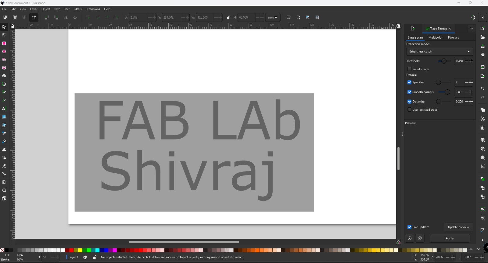
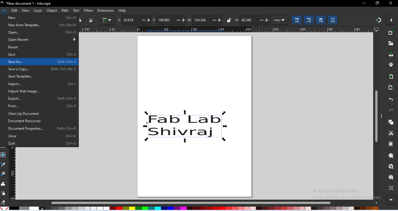
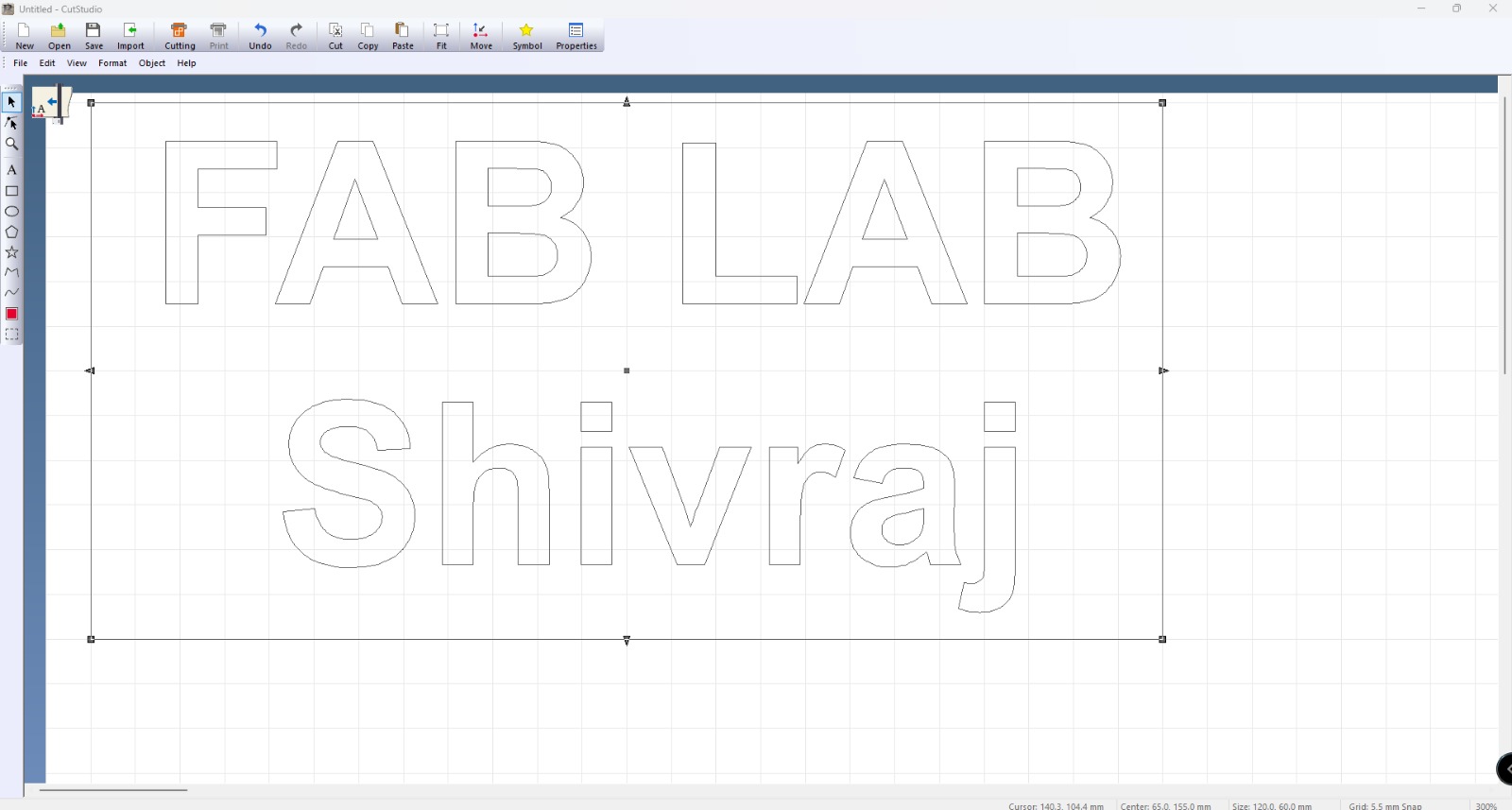
| STEP 1: First, I opened Inkscape, typed the name, and set its dimensions. |
STEP 2: Then, I went to the file menu, clicked on "Open New File," imported the logo into Inkscape, and set its dimensions. |
 |
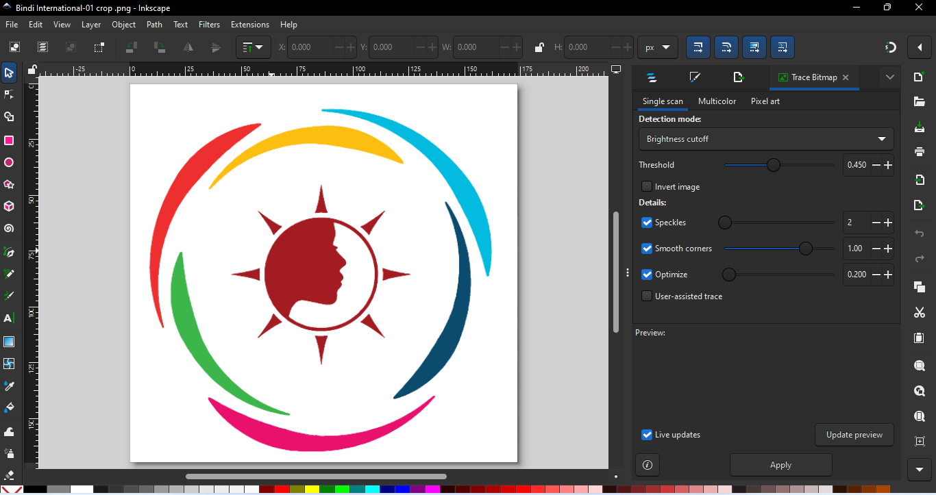 |
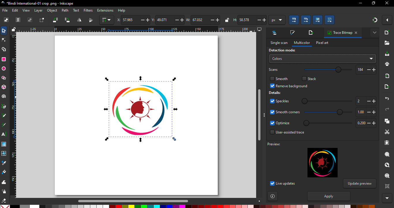
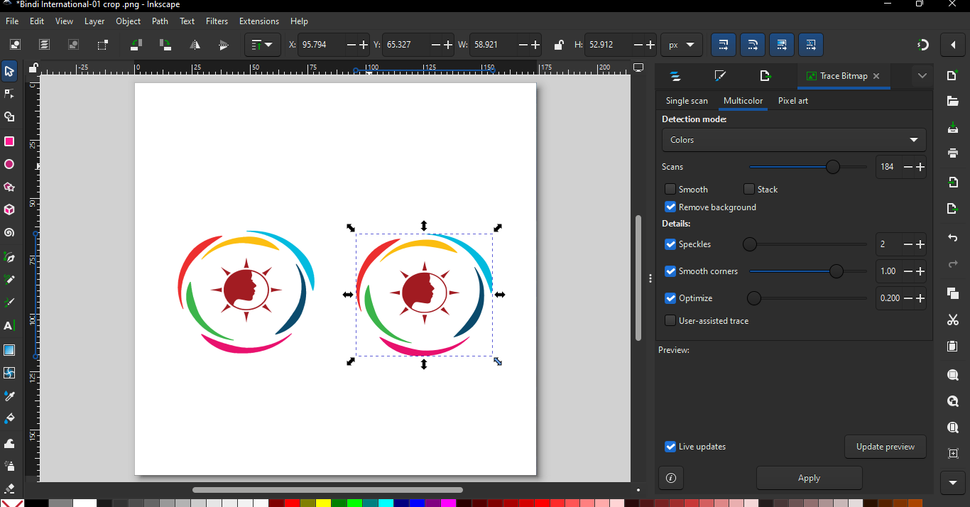
| STEP 3: Next, I used the "Trace Bitmap" tool to convert the logo's raster file into a vector format, resulting in a vector logo file. |
STEP 4: Afterward, I deleted the raster file and selected the final vector file. |
Exporting DFX file from inkscape.
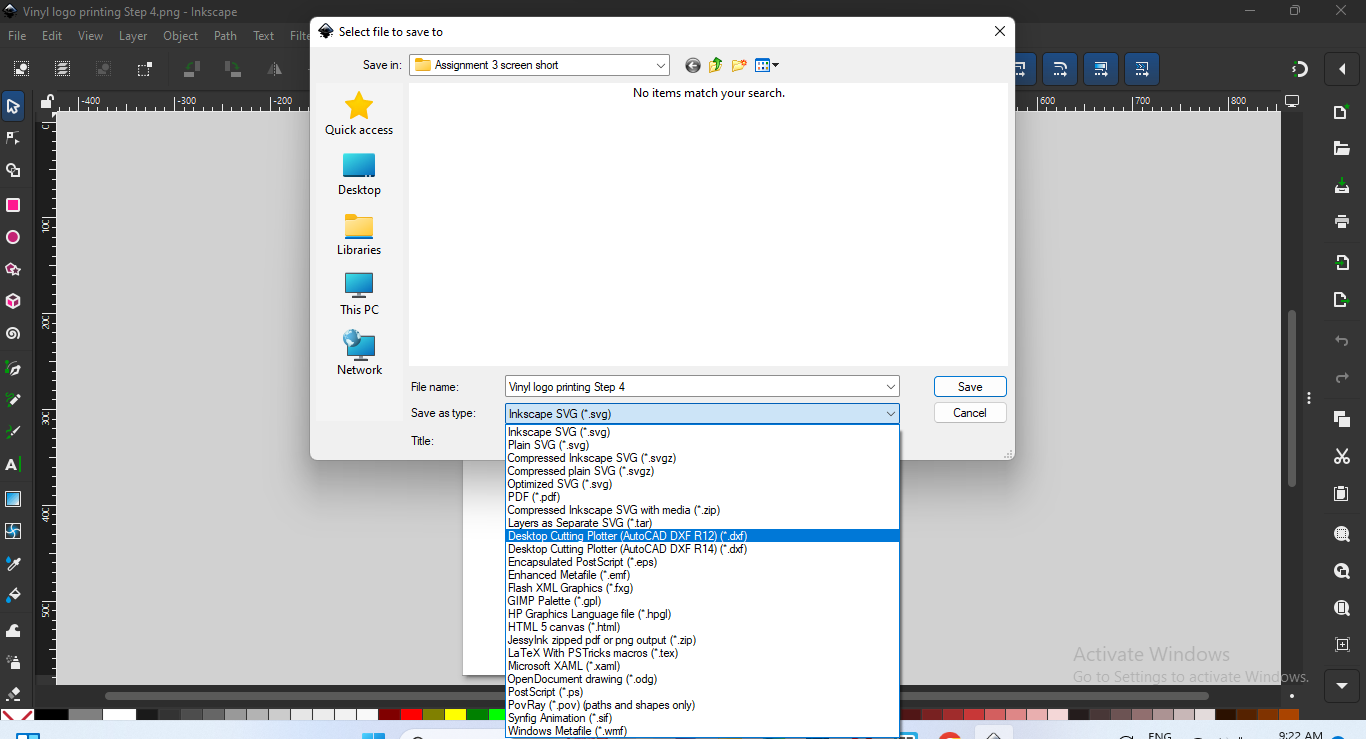
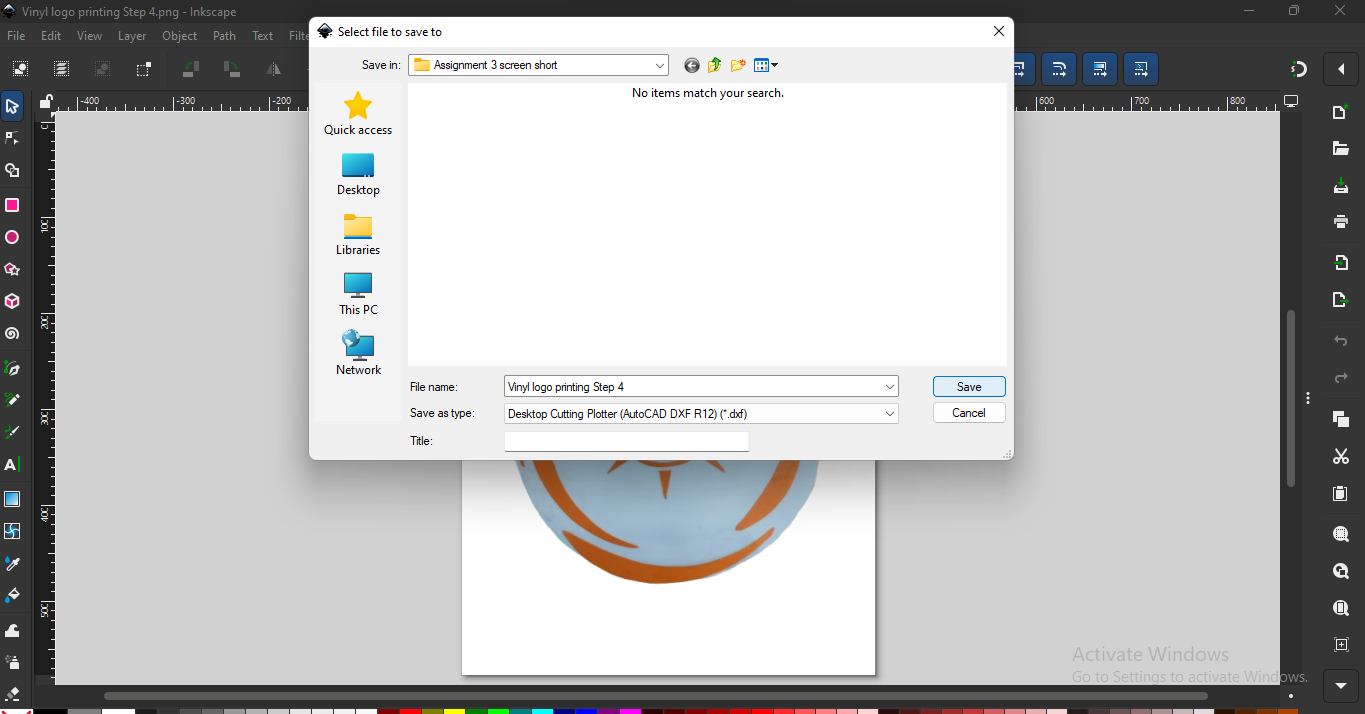
To ensure the file is compatible with the plotter machine’s cutting software, it needs to be in a specific format. I’ve exported the design as a DXF file, which is the preferred format for precise cutting and is fully supported by most plotter software.
Here is the process to download the file in DXF format from Inkscape.
 |
 |
|
|
|
 |
|
|
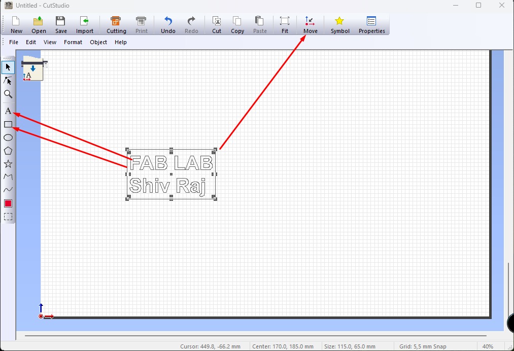
Importing dfx file into cut studo for macking new file which supprt to vinyl cutter
Here is the process of DXF file in CUT STUDIO
 |
 |
|
|
|
 |
|
|
Final Design cutting and printing Process
 |
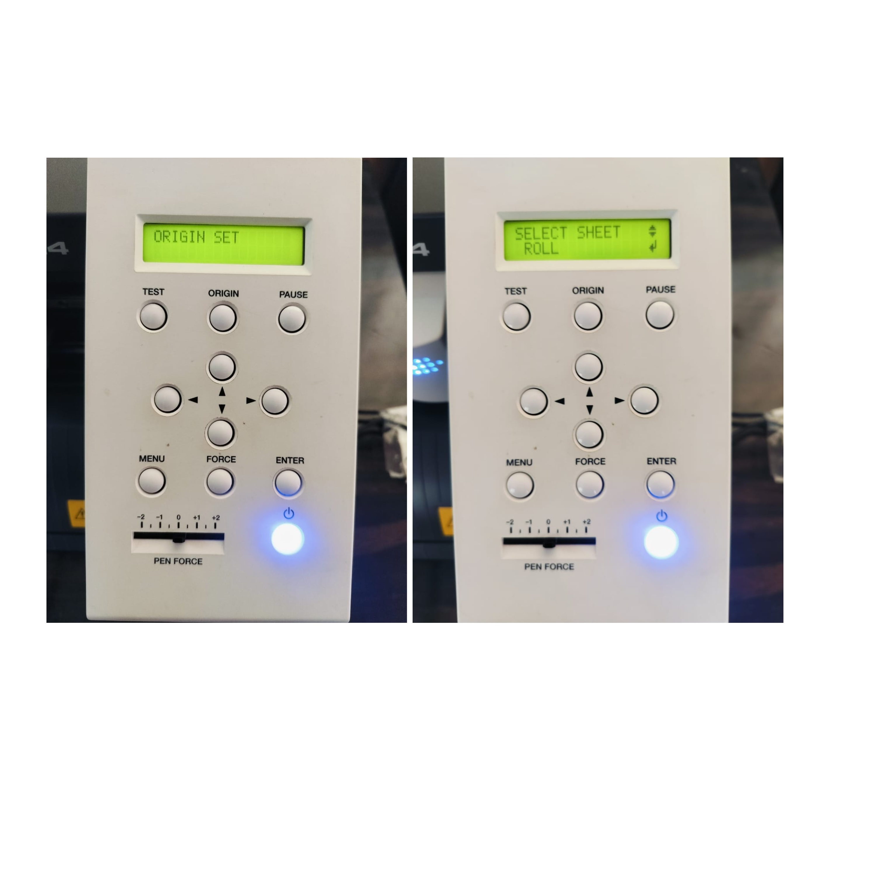 |
| STEP 1: First, the vinyl cutter was powered on, and waited until it was fully operational. Next, the vinyl paper was loaded into the vinyl cutter. |
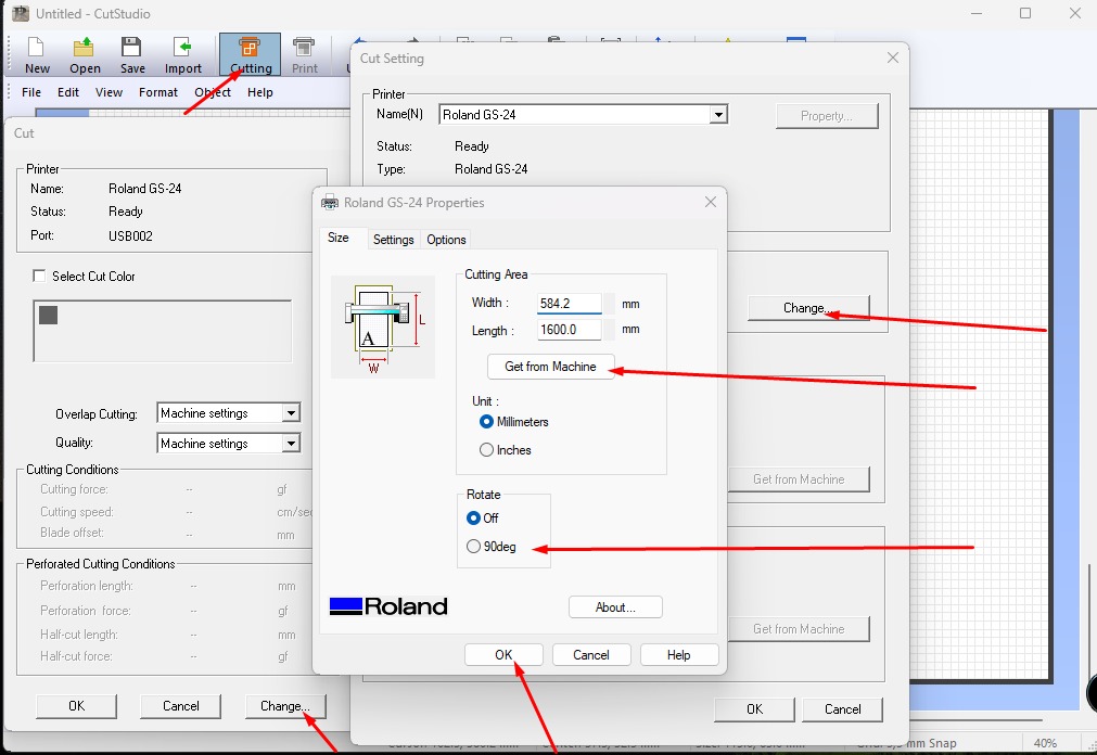
STEP 2: Afterward, the vinyl paper was adjusted using the settings, and the command for printing was set and started printing. |
 |
 |
| STEP 3: After giving the print command, the final design of the logo was created and then extracted. |
STEP 4: Next, the final design of the name was extracted. |
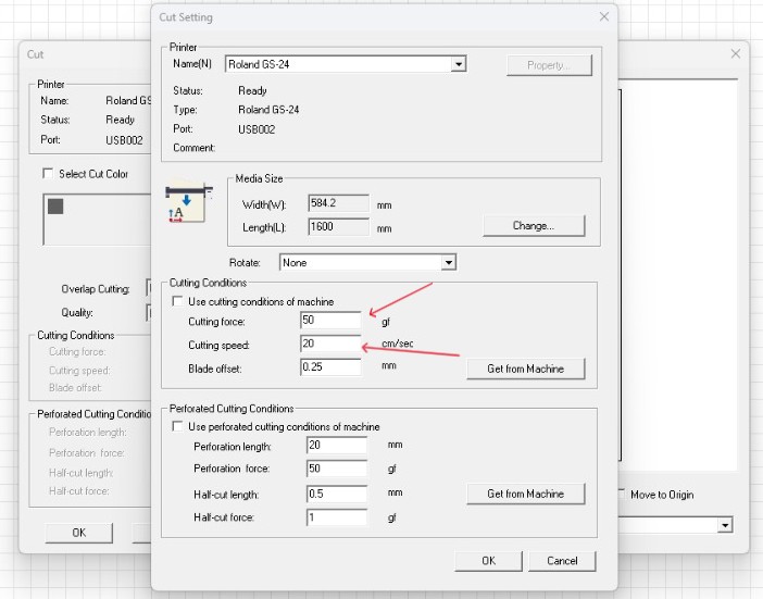
Vinyl Cutter software (Cut Studio) Cutting Speed and Force
I used Cut Studio software for the vinyl cutter. This software allows me to adjust cutting parameters such as cutting speed and cutting force, making it easier to get precise results depending on the material used.
Tools I used for this Assignments
Download Original File's
Fusion 360 Normal design
Fusion 360 Peramactric Design