
Interface and Application Programming
About this Week
This week focused on Interface and Application Programming. I created a mobile application using MIT App Inventor to control an RGB LED via Bluetooth. First, I visited the MIT App Inventor website and signed up for a new account. After logging in, I designed the user interface of the app and created the logic using block-based coding. Once the design and functionality were complete, I downloaded the APK file and installed the app on my mobile phone.
For the hardware part, I used the microcontroller setup that I had previously developed during the Input and Output Devices weeks. I programmed the microcontroller to receive commands via Bluetooth and control the RGB LED accordingly.
Next, I connected the app to the microcontroller using a Bluetooth module. Through the app, I was able to control the color of the RGB LED using on-screen buttons. This practical experience helped me understand how to design and develop a mobile app, how to establish communication between a mobile device and a microcontroller, and how to control physical components through a digital interface.
Overall, it was an exciting and valuable week where I learned how to bridge the gap between software (mobile apps) and hardware (microcontroller systems) to create an interactive system.
Heroshot of the Assignment
 |
 |
|
|
|
Objctive of the Assignment
1. Group Assignment -
2. Individual Assignment
Click here to visit our group assignment
Individual Assignment
Individual Assignment
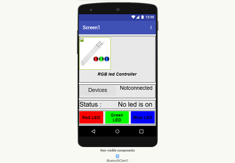
Interface and application programming with MIT APP
For the Interface and Application Programming week, I chose to work with MIT App Inventor because it is a beginner-friendly platform for creating Android applications. Its drag-and-drop, block-based coding environment makes it easy to design and develop apps without requiring prior experience in traditional programming languages. This made it an ideal choice for quickly building a functional app to interface with my hardware project.
The step-by-step process I followed is briefly explained below.
|
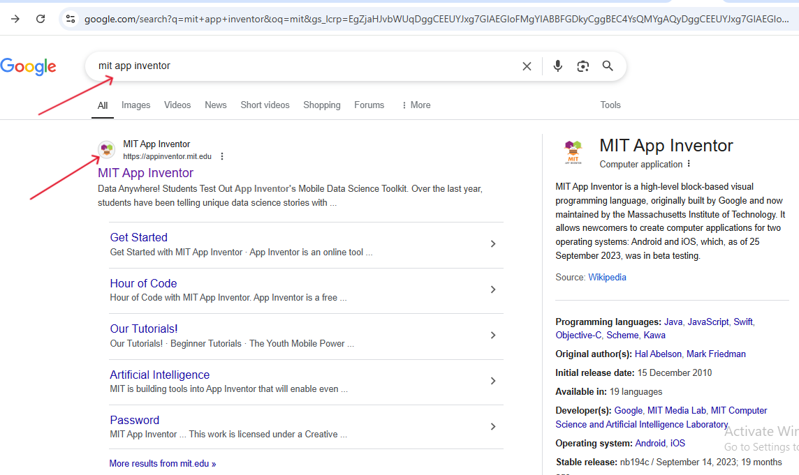
| First, I searched for "MIT App Inventor" on Google and clicked on the first link in the search results. This took me to the official MIT App Inventor website, as shown in the image. |
|
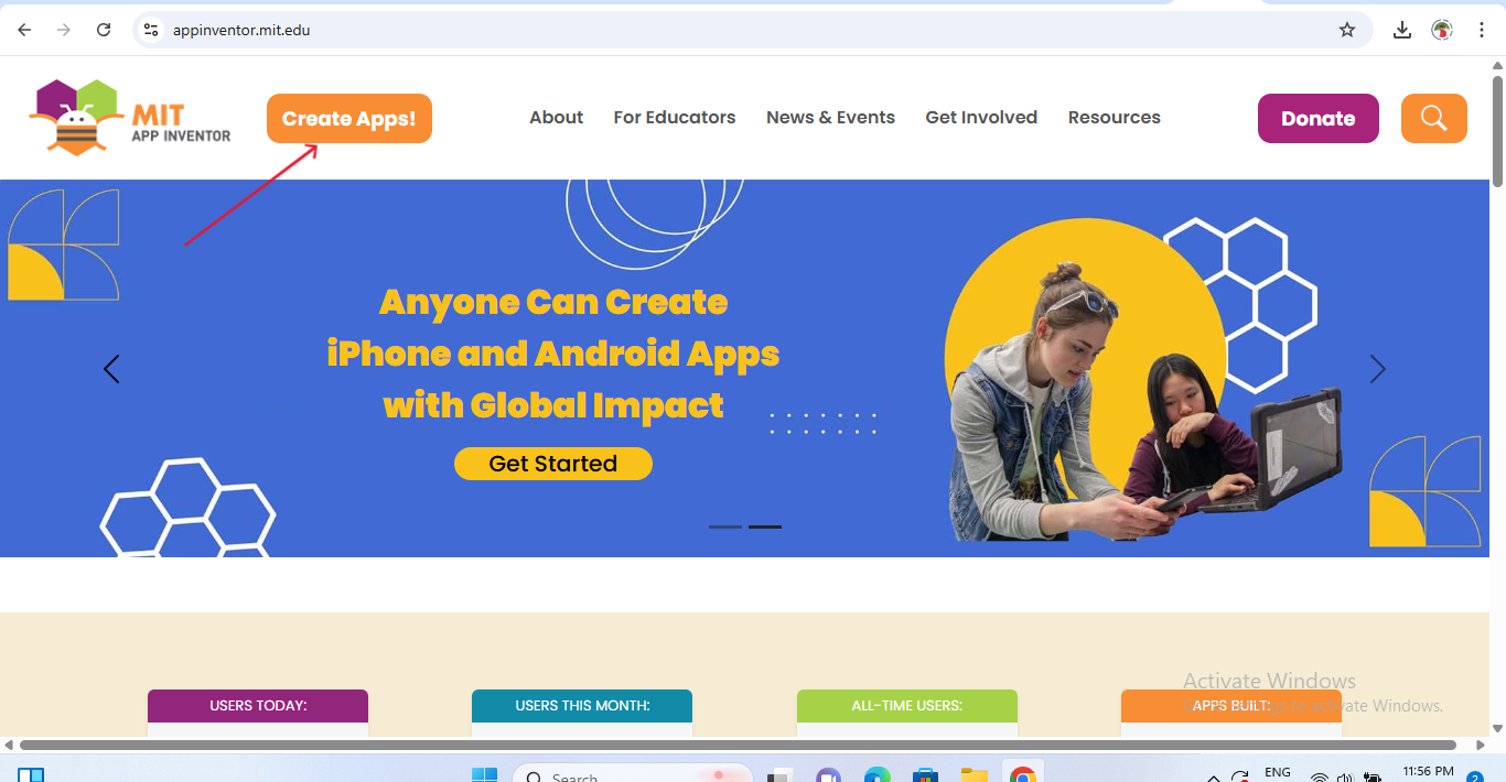
| Then, I clicked on the “Create Apps!” button on the homepage to start building my application. This redirected me to the login page where I signed in with my Google account to access the App Inventor workspace. |
|
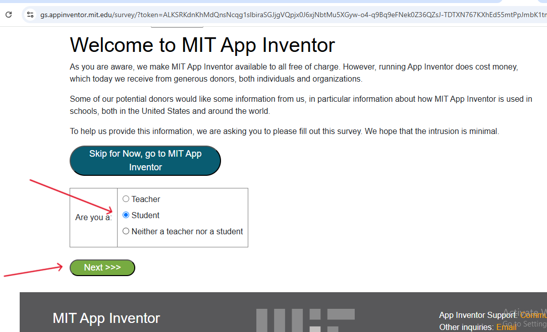
| After logging in with my account (as shown in the image), I completed the initial setup by selecting the appropriate user role. In my case, I chose "Student" from the available options. |
|
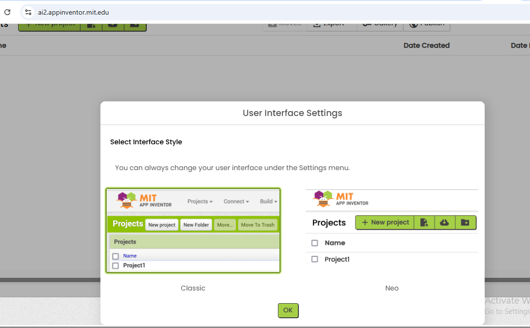
| Next, I selected the preferred interface layout for the App Inventor environment and clicked "OK" to confirm. |
|
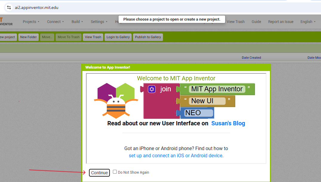
| Then clicked on "Continue" |
|
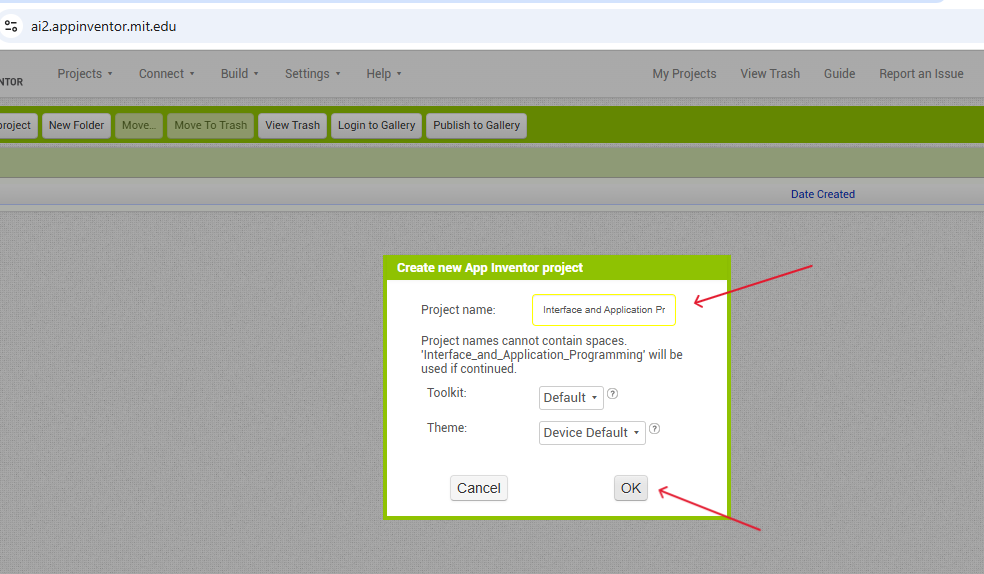
| After that, I named my project to identify it easily later, and then click "OK" to create the new project.This opened the project workspace where I could begin designing and programming my mobile application. |

|
| Workspace area |
|
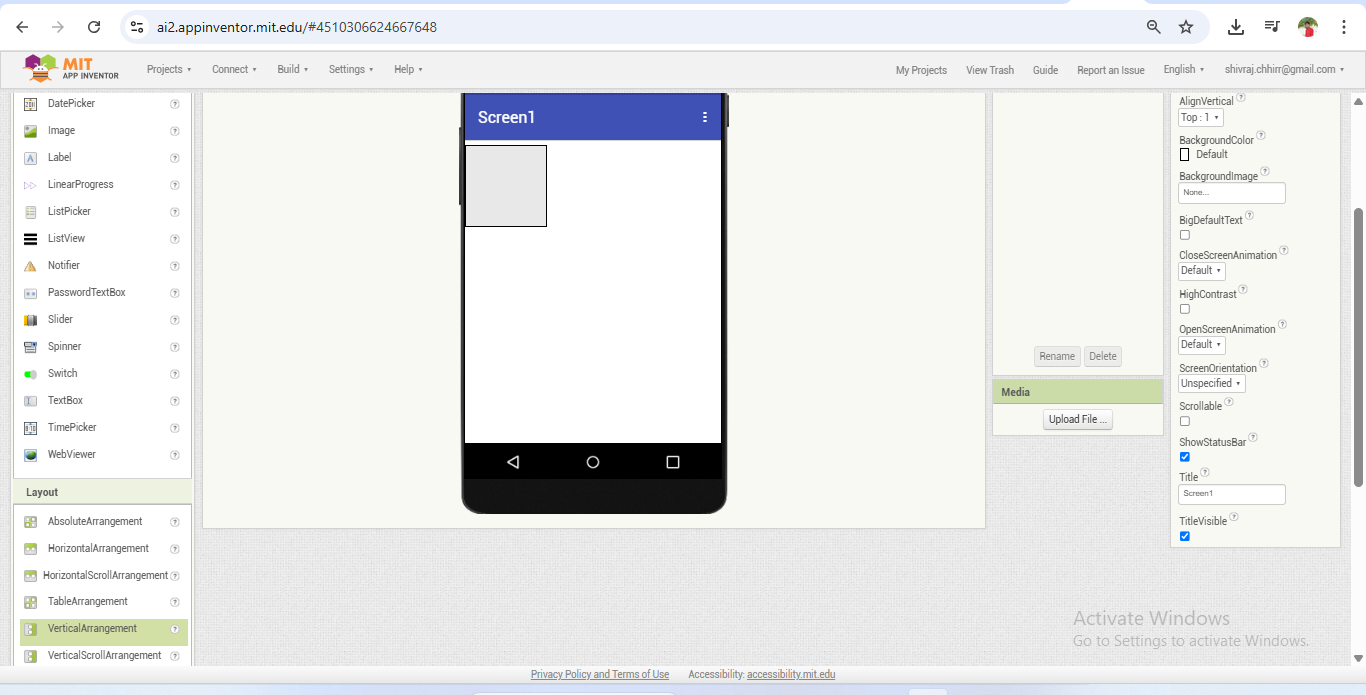
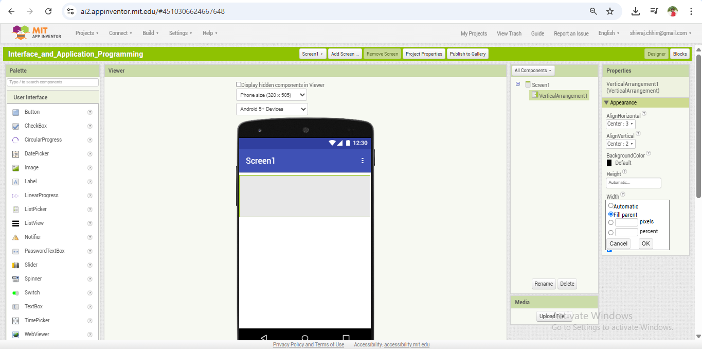
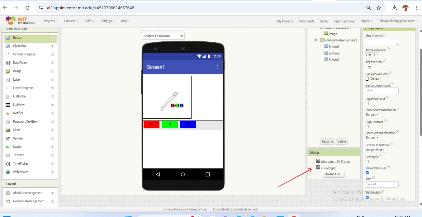
| To start designing the app, I used the options available in the left side panel of the Designer tab. I went to the Layout section and added a Vertical Arrangement component to the screen. This acted as a container or box to neatly organize other UI elements vertically within the app interface. |
|
| Next, I adjusted the height and width of the vertical arrangement box using the properties panel on the right side of the screen. |
|
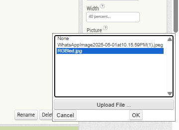
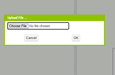
| After that, I added an image inside the layout box. To do this, I selected the box first Then, using the properties panel on the right side, I clicked on the image upload option and selected an image file from my computer to display in the app. |
|
| Once the file was chosen, the image was successfully uploaded and displayed in the workspace area |
|
| Now, the image has been successfully uploaded and is displayed inside the layout box, as shown in the reference image. |
|
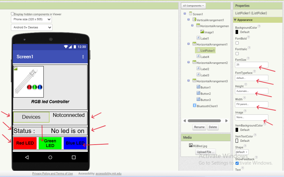
| Next, I used the options available in the left-side panel to add Buttons and Labels to the layout. I customized their dimensions, such as height and width, using the properties panel on the right to fit the app design properly. After setting up the interface components, I navigated to the Connectivity section and added the Bluetooth Client component. |
|
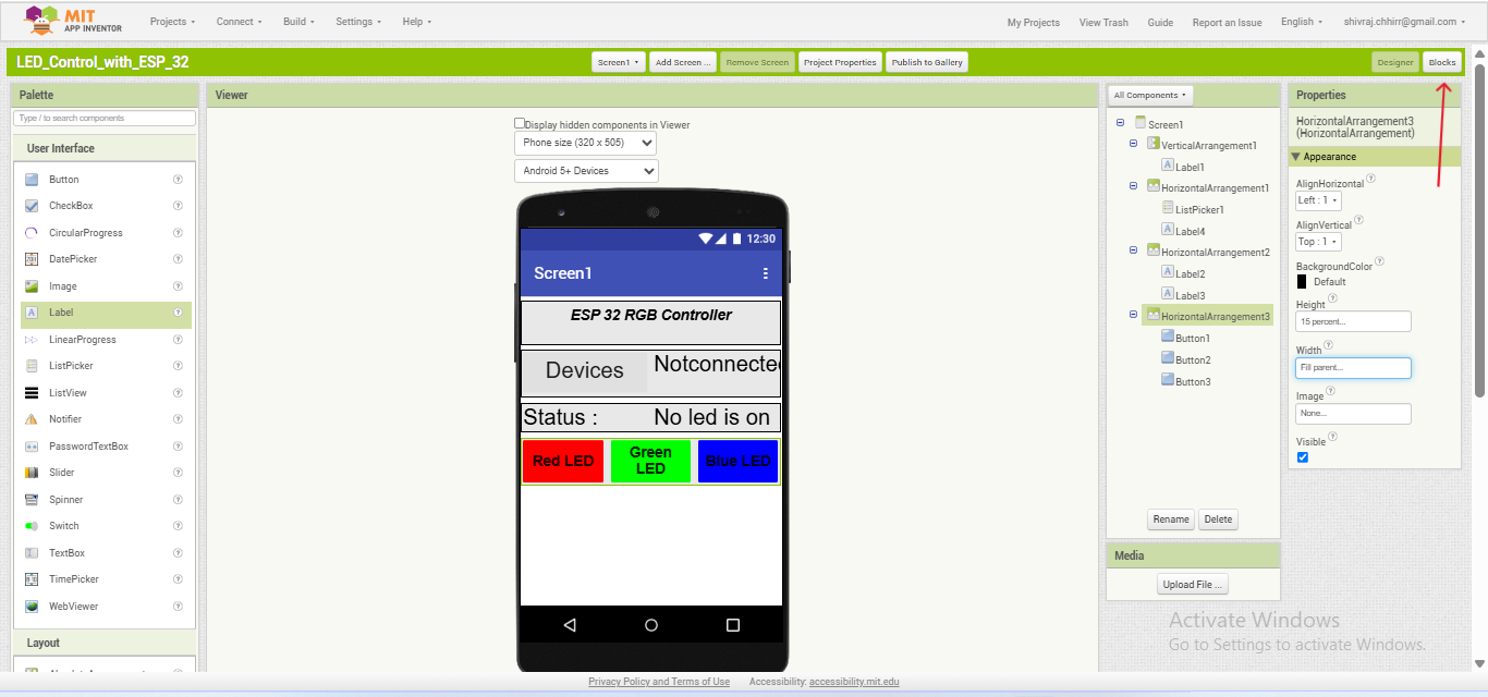
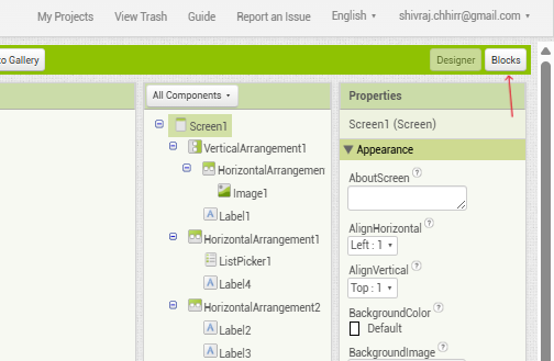
| After adding all the required components in the Designer tab, I clicked on the Blocks option to start programming the logic of the app. |
|
| The Blocks option is located at the top-right corner of the MIT App Inventor interface. By clicking on it, I accessed the block-based programming area. |
|
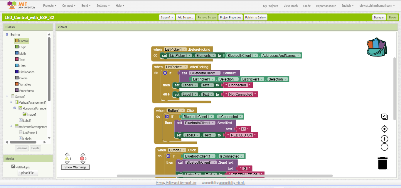
| Now, the block coding area was open. I began programming by using the available components listed in the left-side panel. By dragging and connecting the relevant blocks, I created the code for my project. |
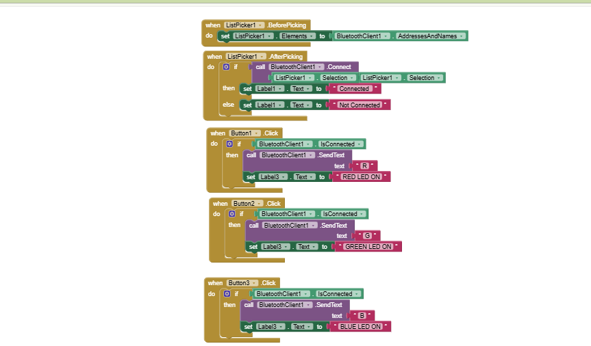
|
| This is the final block-based coding for my project. I created this logic to control an RGB LED through the mobile app, allowing it to be turned on and off color-wise using buttons. For the hardware, I used the ATtiny microcontroller, which receives the Bluetooth commands sent from the app and controls the LED accordingly |
|
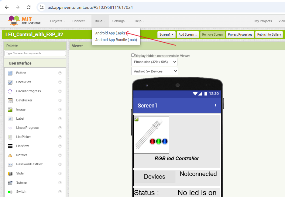
| After completing the final block coding and app design, I returned to the Designer section. Then, I clicked on the Build option in the top menu and selected Android App (.apk). |
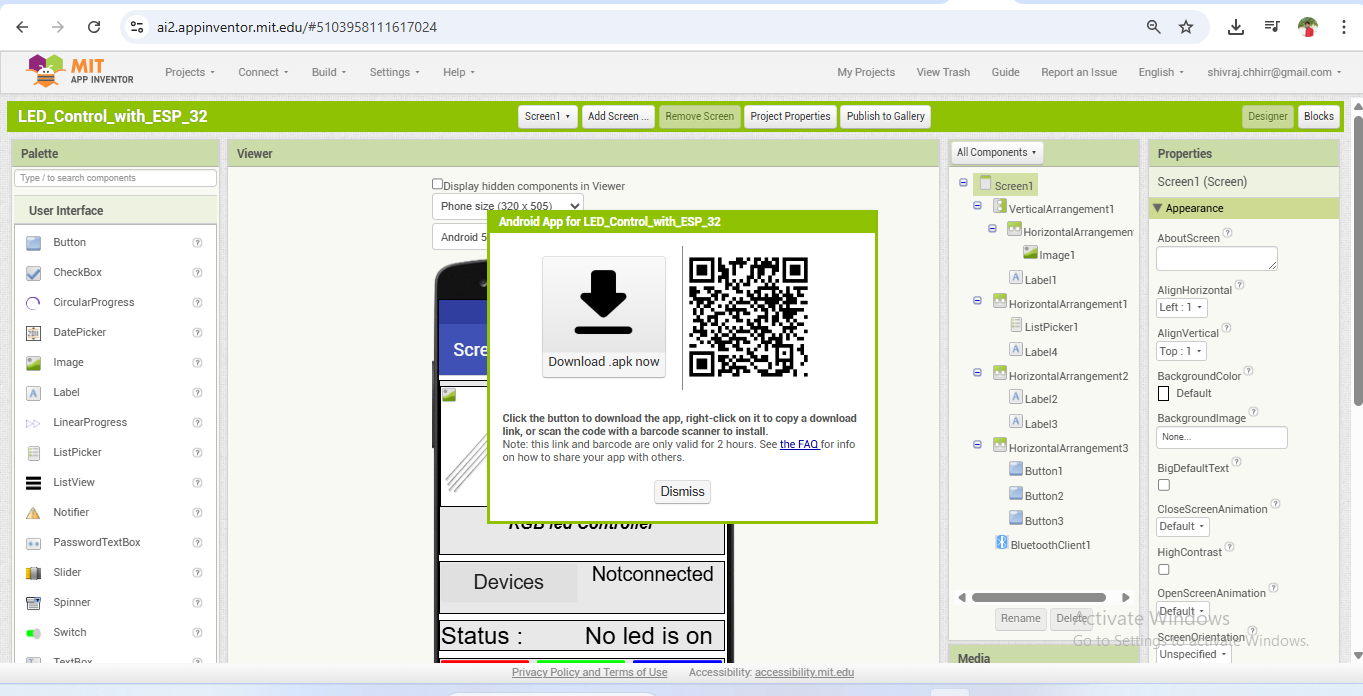
|
| After that, a download option appeared for the Android app. I downloaded the .apk file and then transferred it to my smartphone and installed it. |
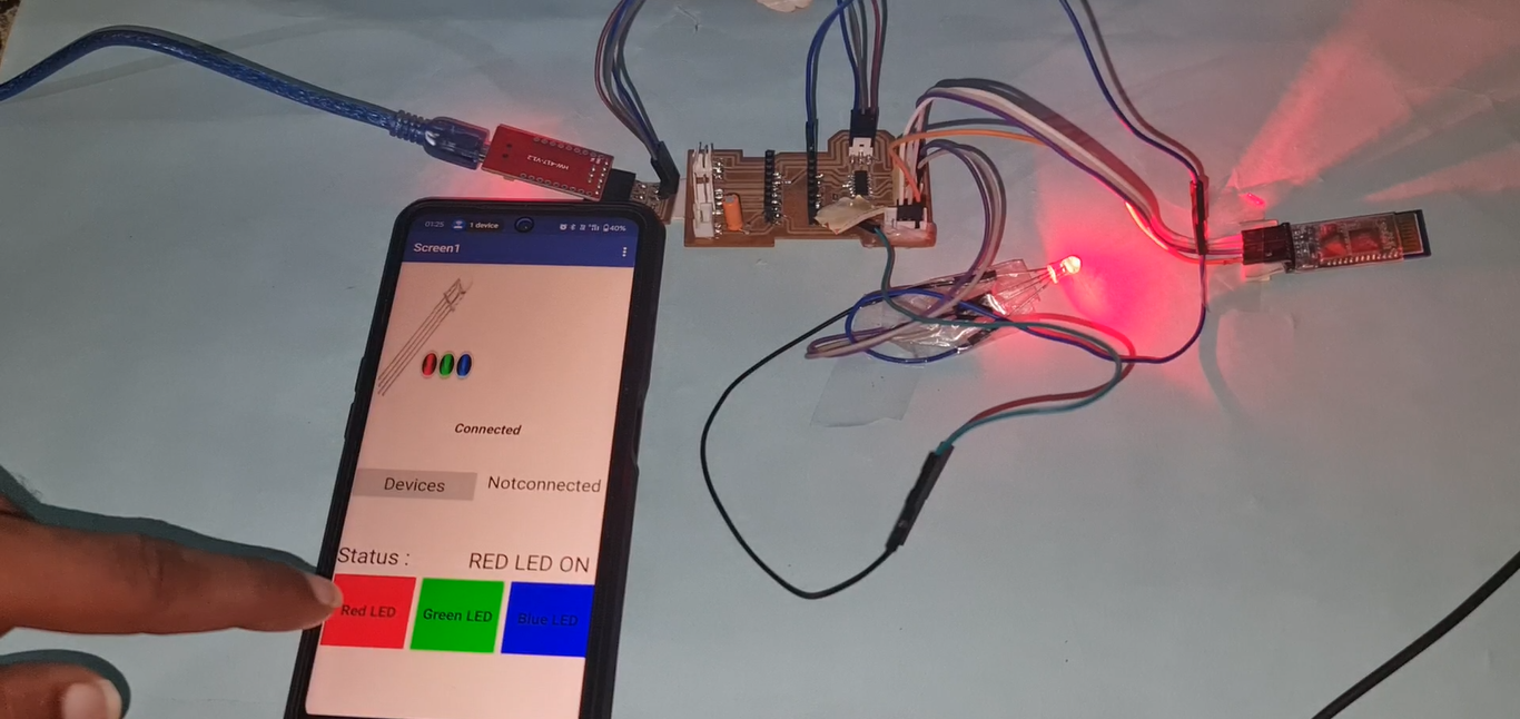
| In the video, you can see how the LED responds to the button clicks from the MIT app interface, with each color (Red, Green, Blue) turning on as the corresponding button is pressed. |
Interface and application programming with Processing
For Interface and Application Programming, I also used Processing, as it is a powerful and flexible platform for creating visual applications that can interact with hardware. Processing is especially useful for beginners and allows easy integration with microcontrollers through serial communication. I used it to create a simple graphical user interface (GUI) that could send commands to the microcontroller, providing an alternative way to control the RGB LED besides the mobile app.
The step-by-step process I followed is briefly explained below.
%20Assignment%2014.png)
|
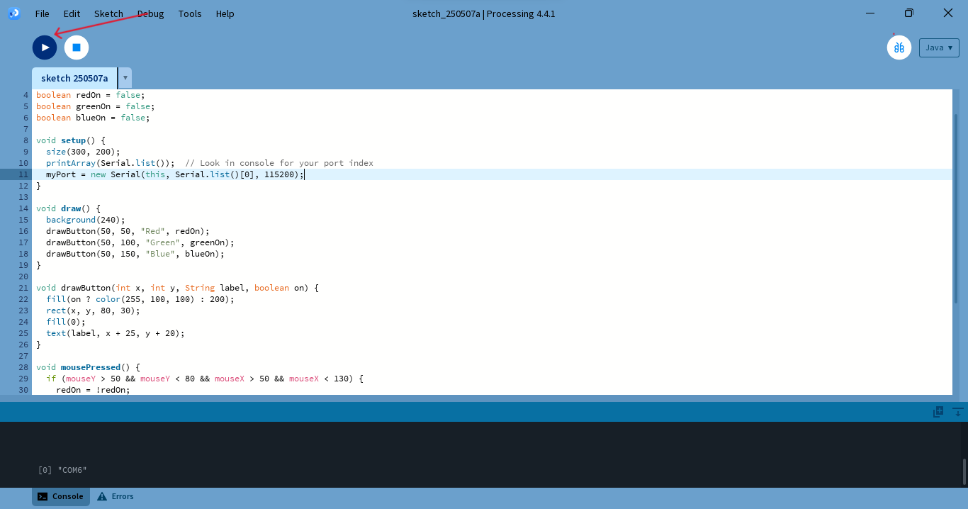
| To control the RGB LED using Processing, I first programmed the Xiao ESP32-C3 microcontroller using the Arduino IDE. In the Arduino code, I enabled serial communication, which allowed the Processing software and the microcontroller to communicate with each other. This setup made it possible for commands sent from the Processing interface to be received by the ESP32-C3, enabling real-time control of the RGB LED. |
|
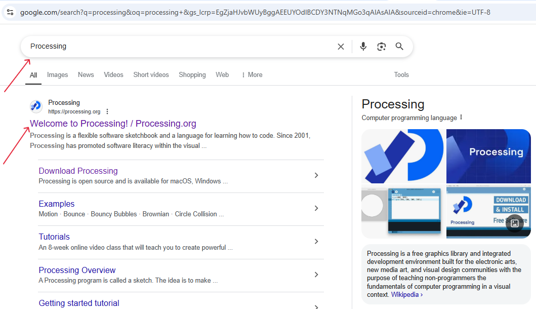
| First, I searched for "Processing" on Google and clicked on the first link in the search results. This took me to the official processing website, as shown in the image. |
|
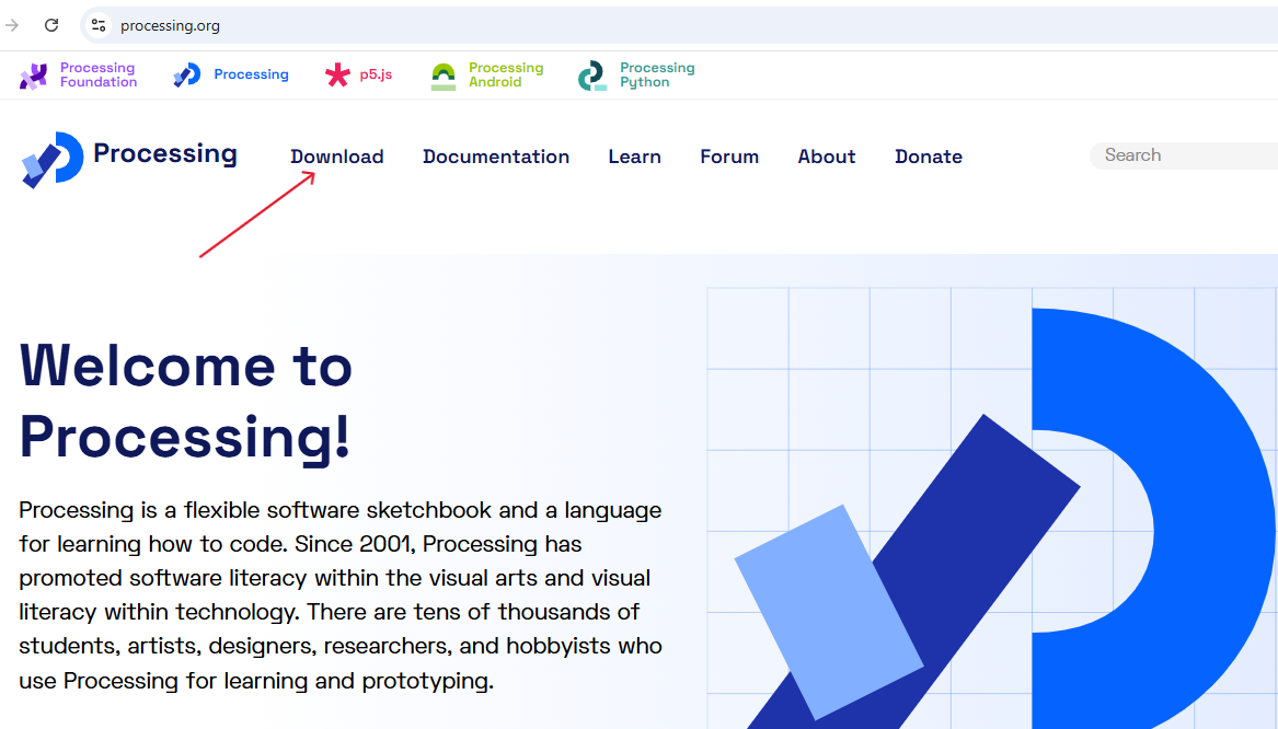
| Then clicked on the Download. |

|
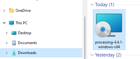
| To get started, I clicked on the Download Processing button and downloaded the software |
|
| Processing donwloaded in the device. |
|
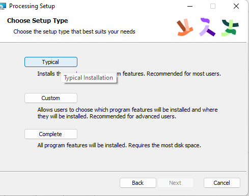
| During the installation process, I configured the necessary settings by choosing from the available options such as Typical, Custom, and Complete installation. |
|
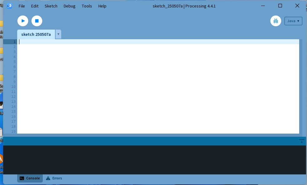
| After the installation complete, the Processing software interface opened and looked like this (as shown in the image). The interface includes a code editor area, a toolbar at the top, and a console at the bottom for displaying messages and debugging information. This environment is where I wrote and ran my code to control the RGB LED. |
|
| I created a new sketch and began writing the code to design a simple graphical user interface (GUI). This interface included buttons to send commands (like "RED", "GREEN", "BLUE") over the serial port to the Xiao ESP32-C3 microcontroller. These commands were interpreted by the microcontroller to turn the RGB LED on and off based on the color.After writing the code, I clicked on the Run button. |
|
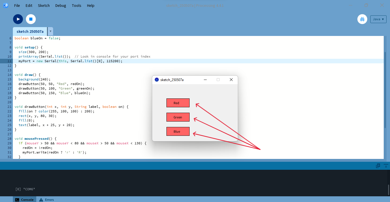
| After running the code in Processing, three buttons appeared on the interface—Red, Green, and Blue—each designed to control the corresponding color of the RGB LED. I then powered on the Xiao ESP32-C3 microcontroller, and by clicking these buttons in the Processing interface, I was able to successfully operate the RGB LED color-wise. |
| In the video, you can see how the LED responds to the button clicks from the Processing interface, with each color (Red, Green, Blue) turning on as the corresponding button is pressed. |
Original File's Given Below -
Interface and Application programming with "MIT APP" code
Interfaceing and Progrraming with "Processing" code
Summary
In this week's assignment on Interfacing and Application Programming, I worked on creating applications to control an RGB LED using two different platforms: MIT App Inventor and Processing.
First, I used MIT App Inventor to design a mobile application. I created the user interface using layout tools and added functionality using block-based coding. After building the app, I installed it on my Android phone. I connected it to an ATtiny microcontroller with an external Bluetooth module, allowing me to control the RGB LED using buttons in the app for Red, Green, and Blue colors.
In addition to the mobile interface, I also explored Processing, a desktop-based programming environment. I created a graphical user interface with buttons and connected it to a Xiao ESP32-C3 microcontroller using serial communication. The ESP32-C3 was programmed via the Arduino IDE to receive commands from Processing and control the RGB LED accordingly.
Both platforms demonstrated successful interfacing between software applications and microcontroller-based hardware.
Conclusion
This assignment helped me gain hands-on experience in building user interfaces and interfacing them with hardware. Using MIT App Inventor, I learned how to design mobile apps and communicate with microcontrollers via Bluetooth. Through Processing, I learned how to build a GUI on a PC and send commands over serial to control devices.
Overall, the project was successful and gave me practical knowledge of how to integrate software applications with embedded hardware systems, a key concept in IoT and embedded systems development.