
About this week
This week, we explored the fundamentals of networking and communication between microcontrollers. The primary objective was to understand how two microcontrollers can exchange data with each other using different communication methods.
To begin with, we used two microcontrollers and experimented with wired communication protocols such as I2C. Once we successfully established communication through physical connections, we moved on to wireless communication using Wi-Fi (via ESP32 modules), which allowed the devices to interact without any physical connection.
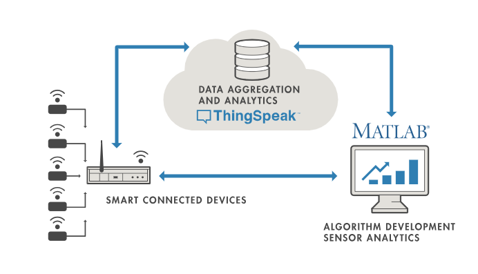
As a final step, we explored cloud-based communication using ThingSpeak, an IoT analytics platform. This enabled one microcontroller to send sensor data to the cloud, while the other microcontroller fetched that data and triggered an output action accordingly.
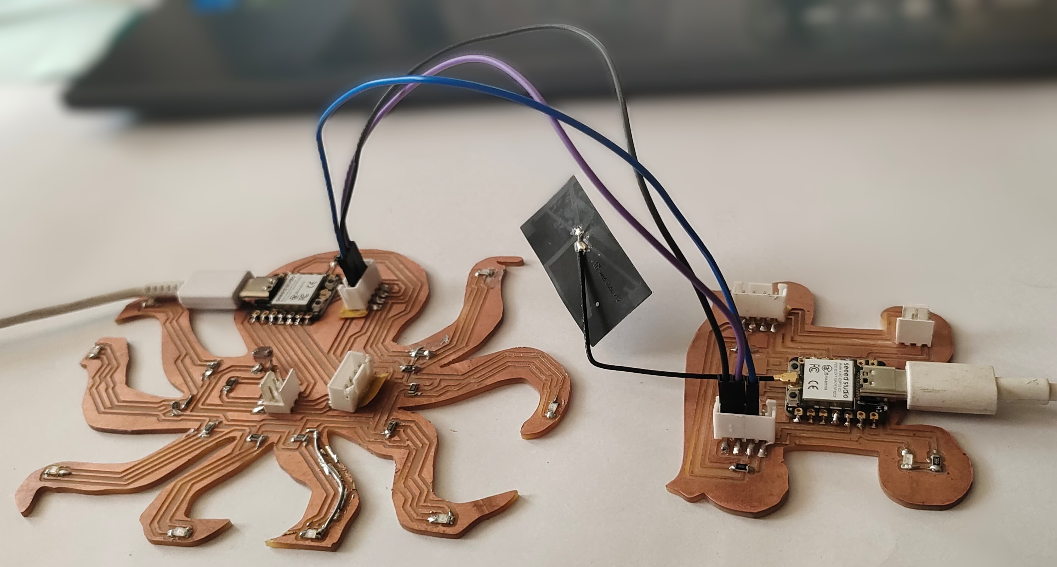
In our setup, we configured one microcontroller as the input node, connected to various sensors (e.g., IR sensor, Smoke sensor, Sound sensor sensors), and the second microcontroller as the output node, which was connected to output devices like RGB LED, Normal LED, OLED display and LCD display . The communication was implemented in a one-way direction, where data flowed from the input device to the output device.
Through this assignment, I learned how different types of communication protocols work. Also gained practical experience in data handling, real-time interaction, and remote control using IoT.
Heroshot of the Assignment
 |
 |
|
|
|
 |
 |
|
|
|
Objctive of the Assignment
1.Group Assignment -
2. Indivisual Assignment -
What is Networking and Communications ?
When two or more microcontrollers are connected to each other—whether through wired connections, wireless methods like Wi-Fi, or via the cloud—and are able to exchange data, this process is known as Networking and Communication.
In such a setup, we can use sensors as input devices, such as temperature sensors, motion sensors, or light sensors, to collect data from the environment. This data can then be sent to another microcontroller that has various output devices connected to it, such as servo motors, OLED displays, LEDs, RGB LEDs, or speakers.
For example, one microcontroller can be connected to a sensor (like a temputare sensor ) that collects real-time data. This microcontroller then sends the data to a second microcontroller using wired communication (like I2C protocall), wireless communication (like Wi-Fi or Bluetooth), or even through a cloud platform (like ThingSpeak).
On the receiving end, the second microcontroller interprets the incoming data and responds using an output device. For instance, if the temperature crosses a certain threshold, an OLED display can show the value, or an LED can turn on as an alert.
This kind of setup helps demonstrate one-way communication, where one device only sends data (transmitter) and the other only receives and acts on it (receiver). It's a practical example of how IoT (Internet of Things) systems function, where multiple devices communicate and work together in a smart, interconnected way.
Website Reference here
What is a protocol in microcontrollers
In microcontrollers, a protocol defines a set of rules. It acts as a guideline that ensures both microcontrollers use the same language during communication, so there is no interruption and both controllers can understand each other's messages clearly.
Type of protocol
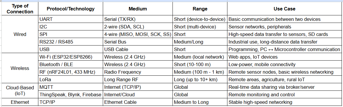
Wireless Protocols
Cloud/IOT Protocos
Wired Protocols
Modulation
Modulation is the process of converting data into radio waves by adding information to an electronic or optical carrier signal. A carrier signal is one with a steady waveform (a constant amplitude and frequency).
The modulation device typically applies modulation to electromagnetic signals. Common examples include radio waves, lasers and optics, and computer networks. However, other modulation applications exist.
Type of Modulation
Website Reference here
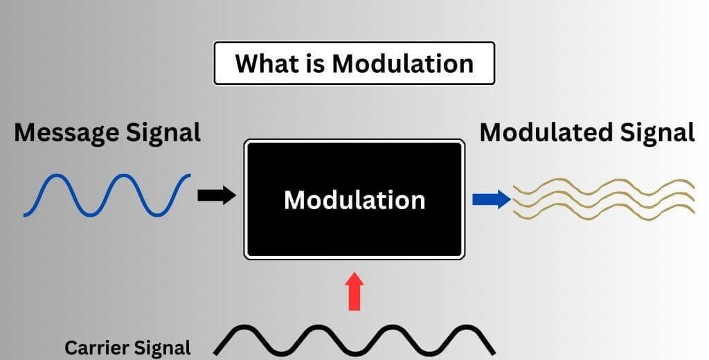
Photo Reference here
Individual Assignment
design, build, and connect wired or wireless node(s)with network or bus addresses and local input &/or output device(s)
In the individual assignment, I explored three types of one way communication with XIAO ESP32C3 :- wired, wireless, and cloud.
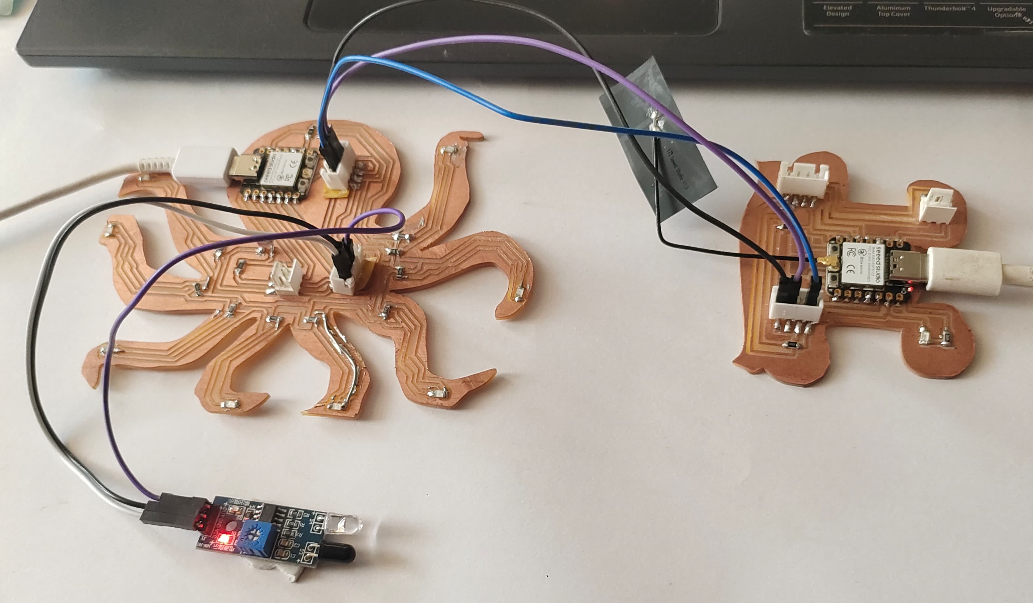
Wired Communication - IR sensor with LED
| |
|
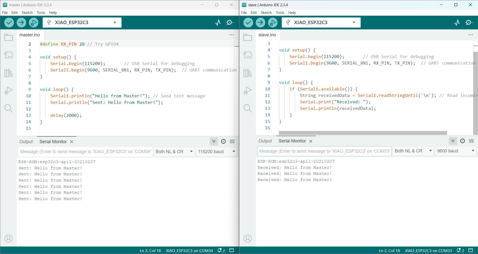
| Two microcontrollers are connected using their RX and TX pins for wired serial communication. |
|
 |
|
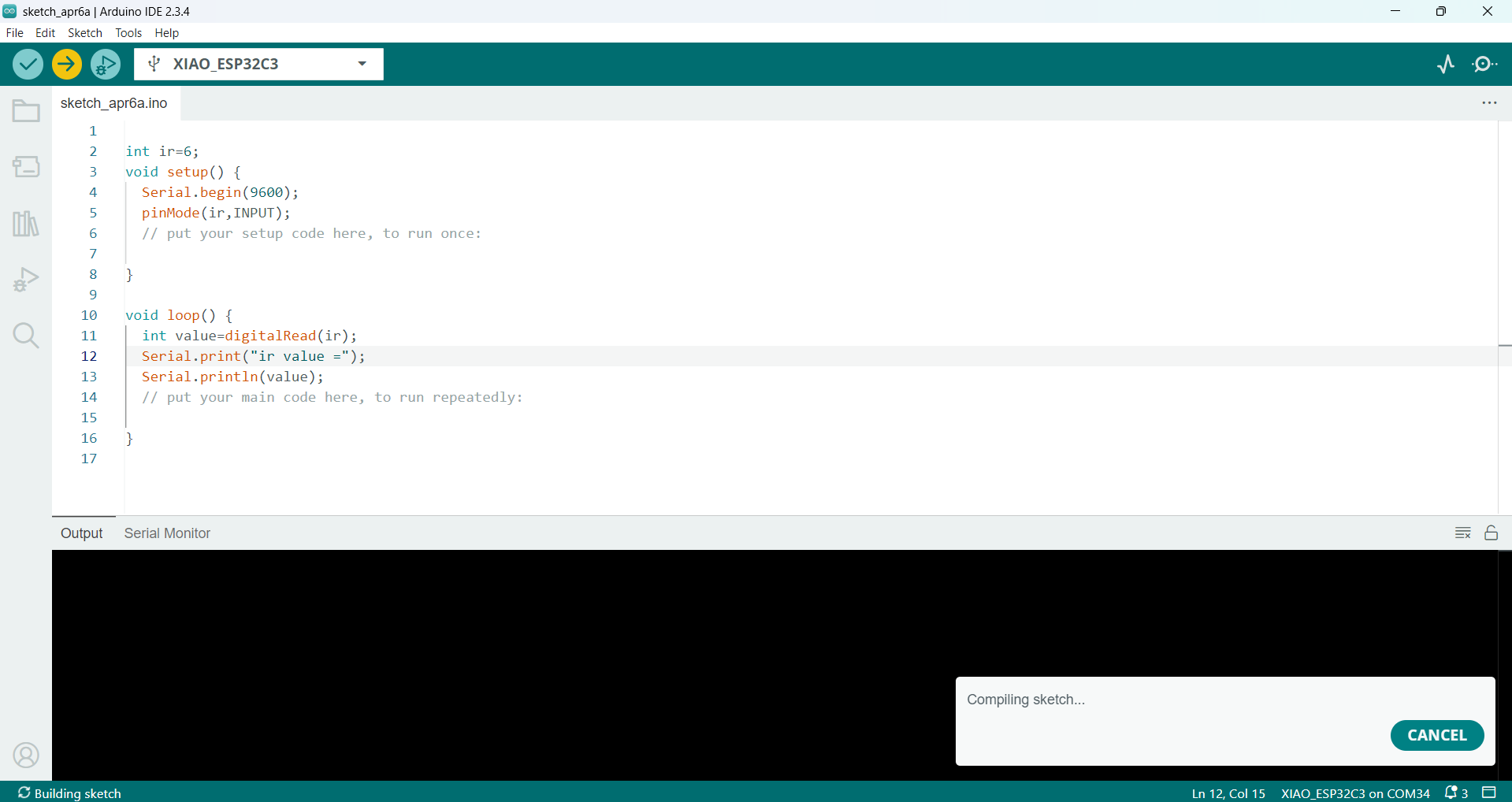
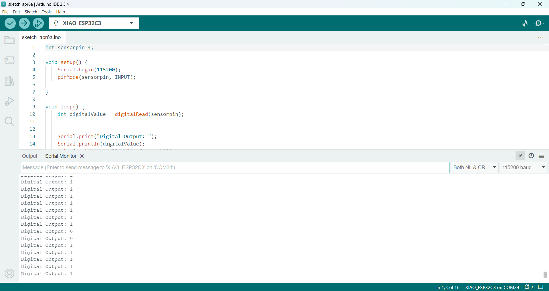
| The IR sensor is connected to one of the microcontrollers. |
|
 |
|
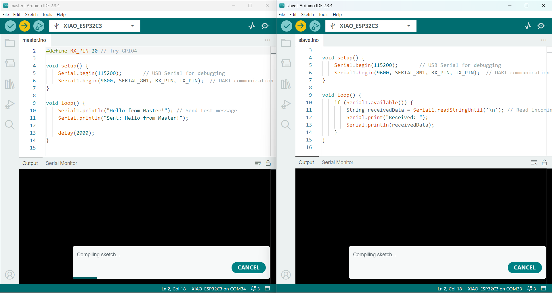
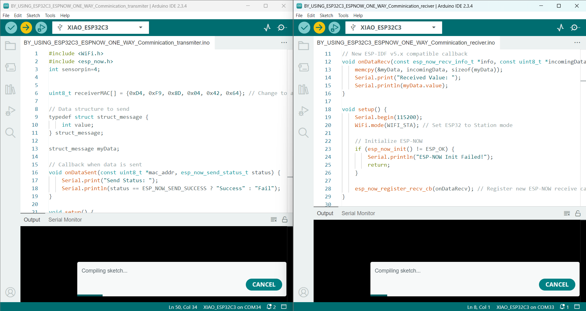
| Programming both microcontrollers for one-way communication. |
|
 |
|
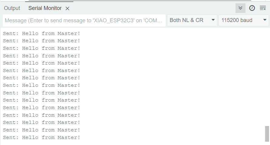
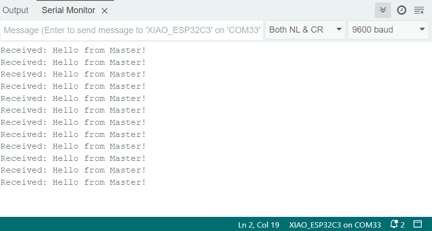
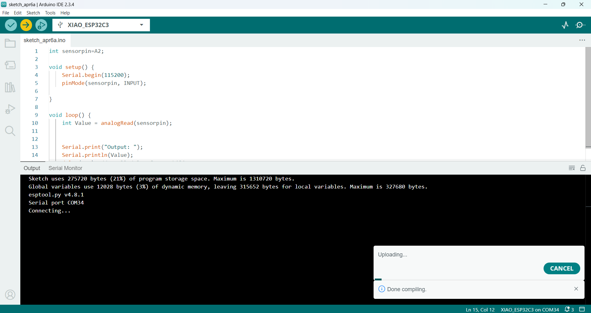
| Data is displayed on the Serial Monitor, indicating successful communication. |
|
 |
|
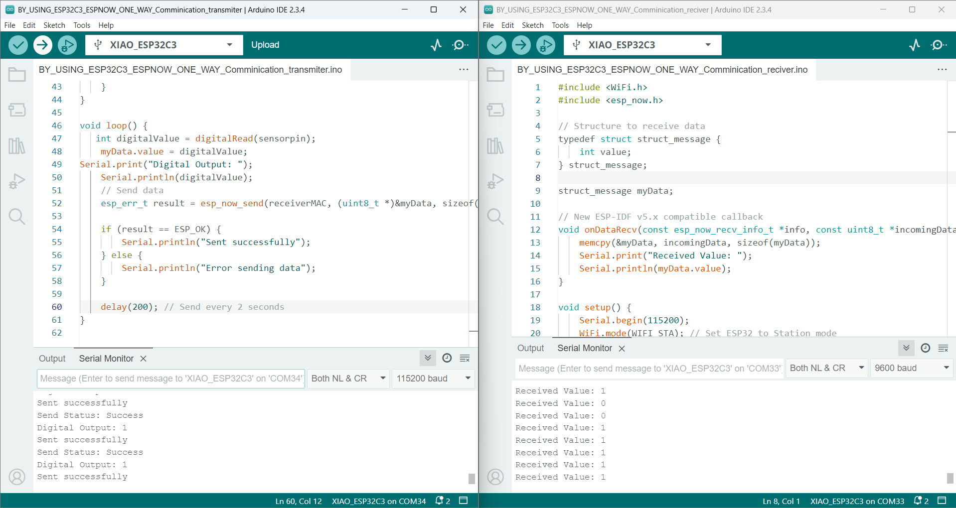
| Data is transmitted from one microcontroller. |
|
 |
|
| Data is received by the other microcontroller. |
|
 |
|
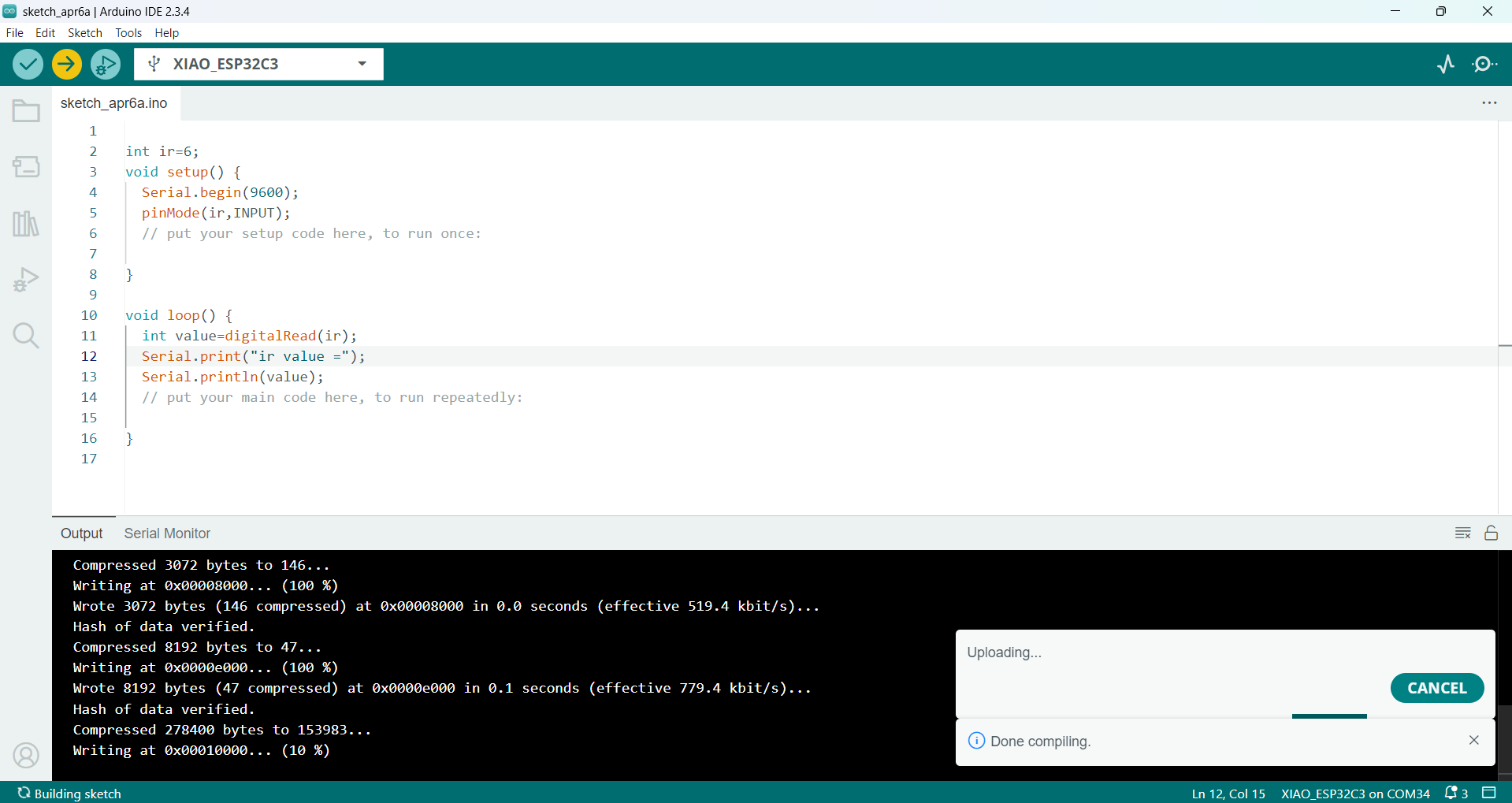
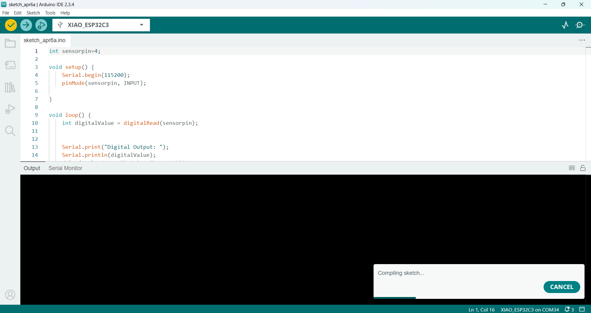
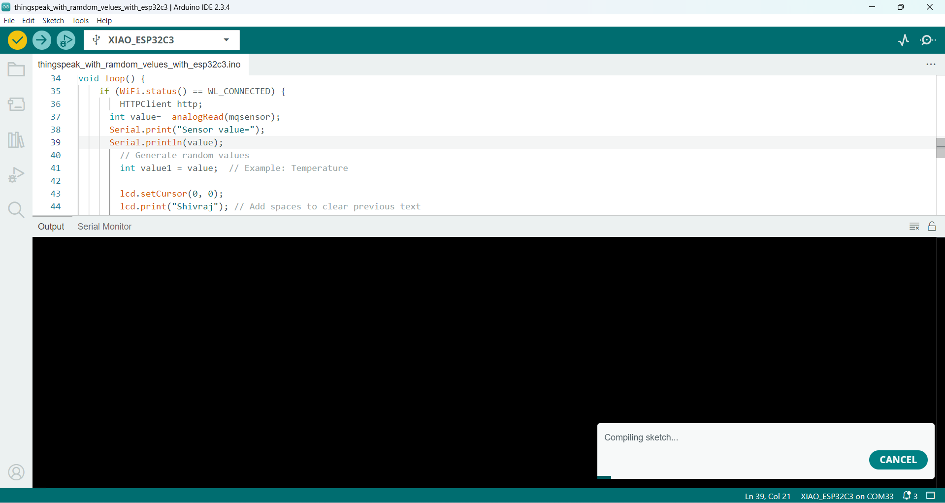
| Final code is compiling. |
|
 |
|
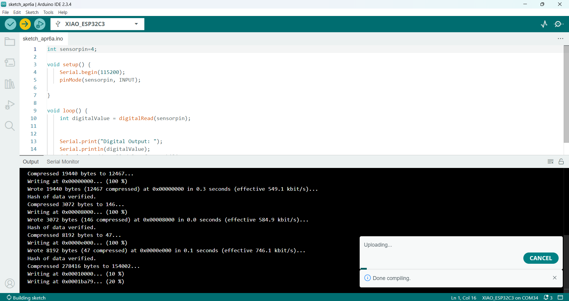
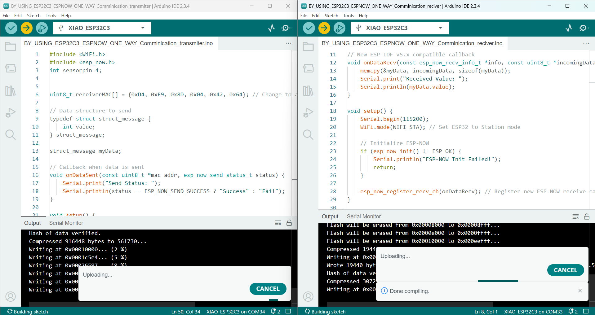
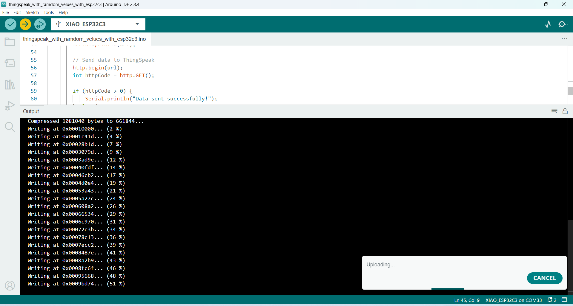
| Uploading final code to the microcontroller. |
|
 |
|
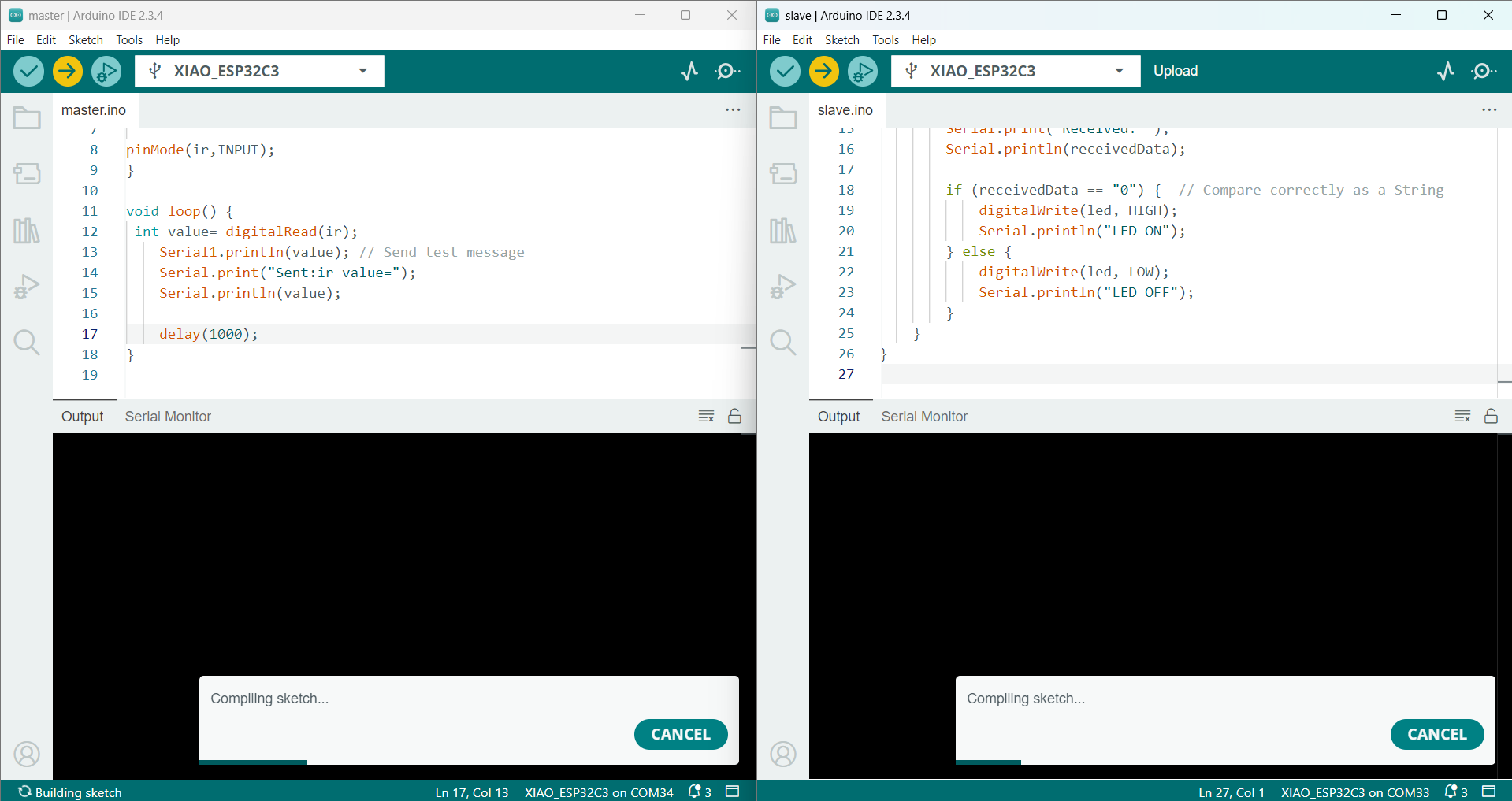
| Compiling and uploading the final code for both microntrollers. |
|
 |
|
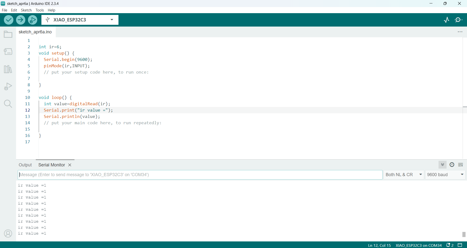
| Data is displayed on the Serial Monitor, indicating successful communication. |
|
| > | |
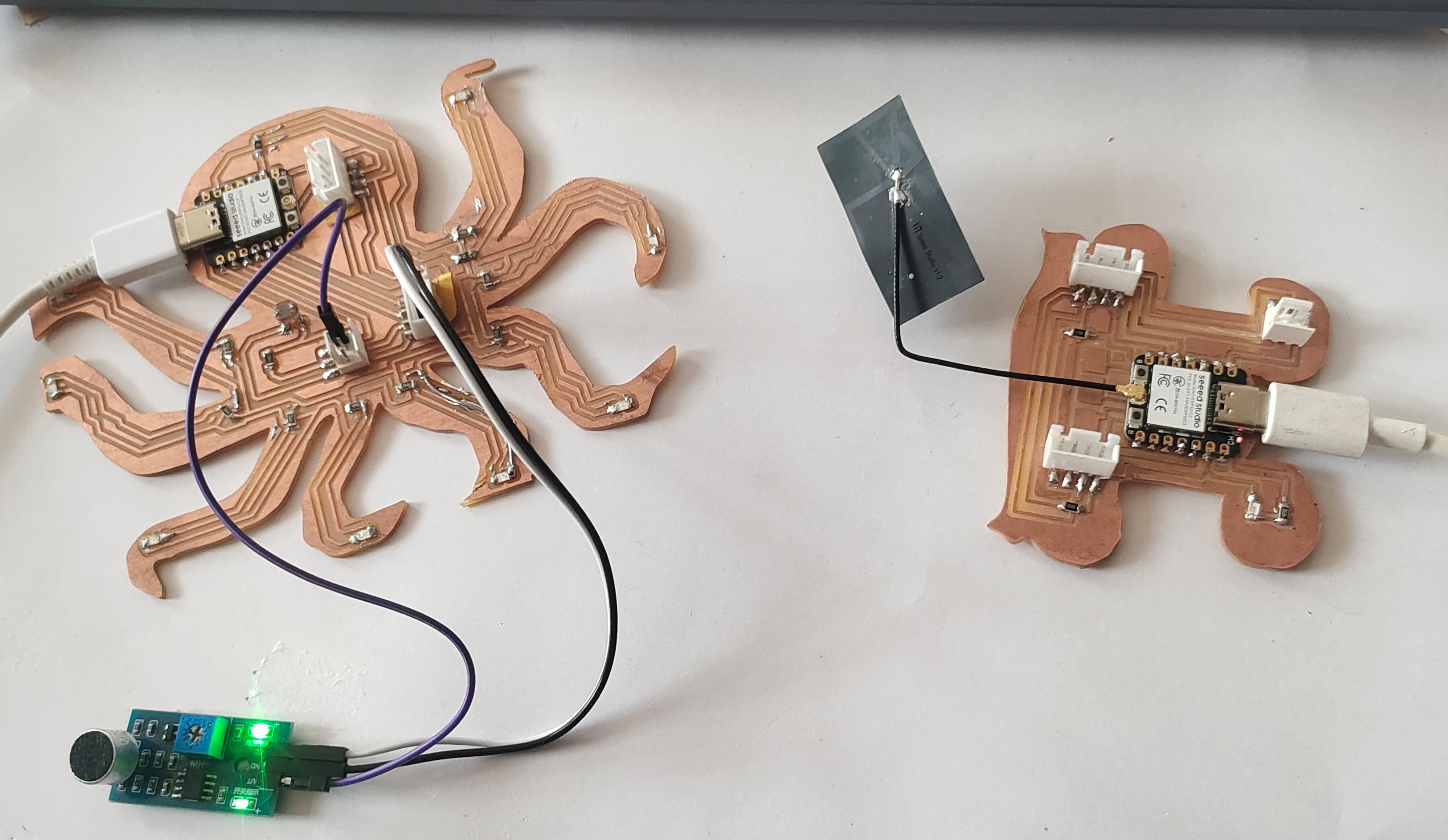
| Wired communication using IR sensor and LED has been successfully completed, and the result here. |
|
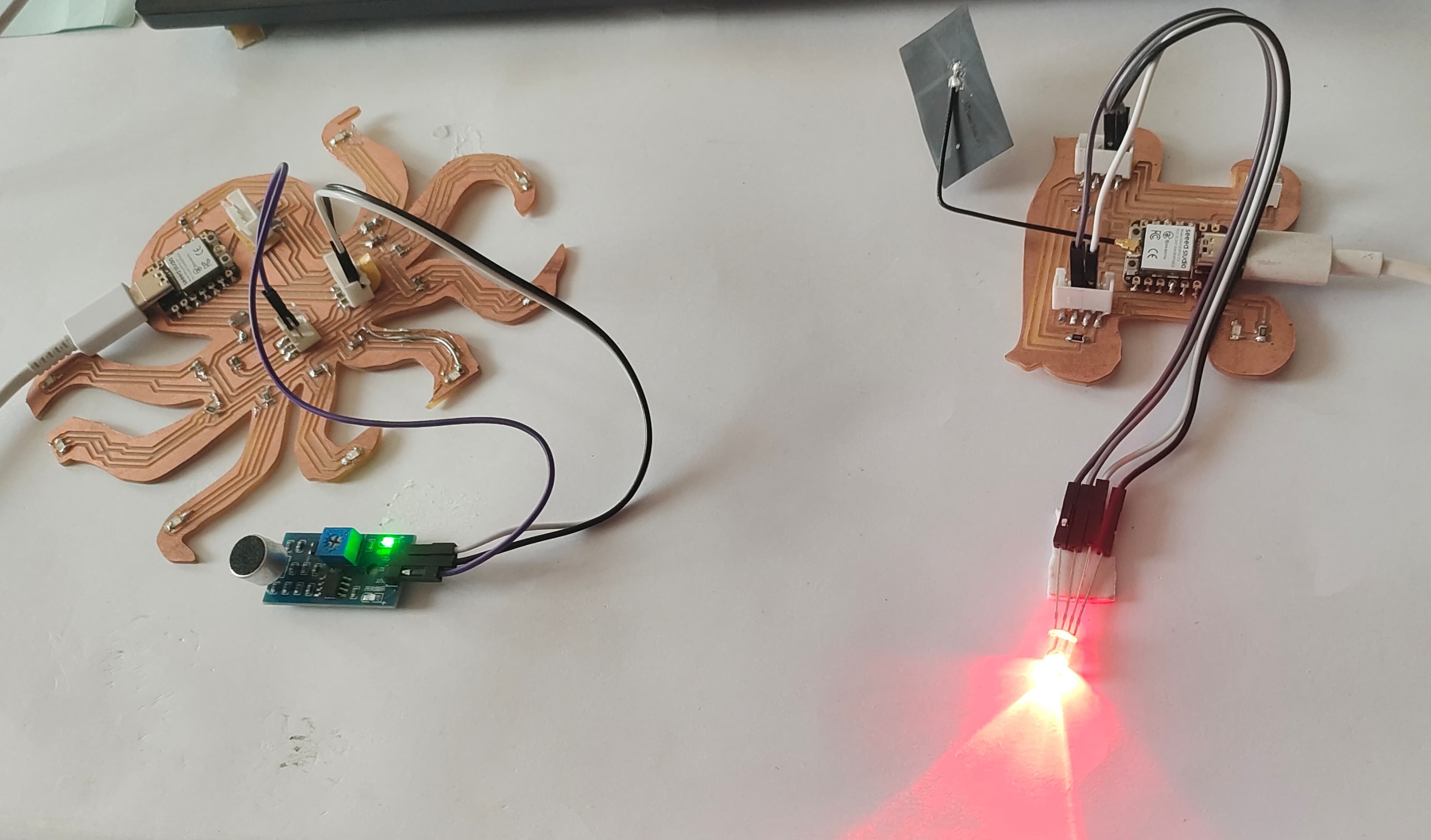
Wireless Communication - Sound Dedction sensor with RGB LED
 |
|
| Two microcontrollers are connected through Wi-Fi for wireless communication. |
|
 |
|
| Uploading the sensor testing code separately. |
|
 |
|
| Uploading in process. |
|
 |
|
| Uploading testing code for Sound sensor and RGB LED |
|
 |
|
| Uploading in process. |
|
 |
|
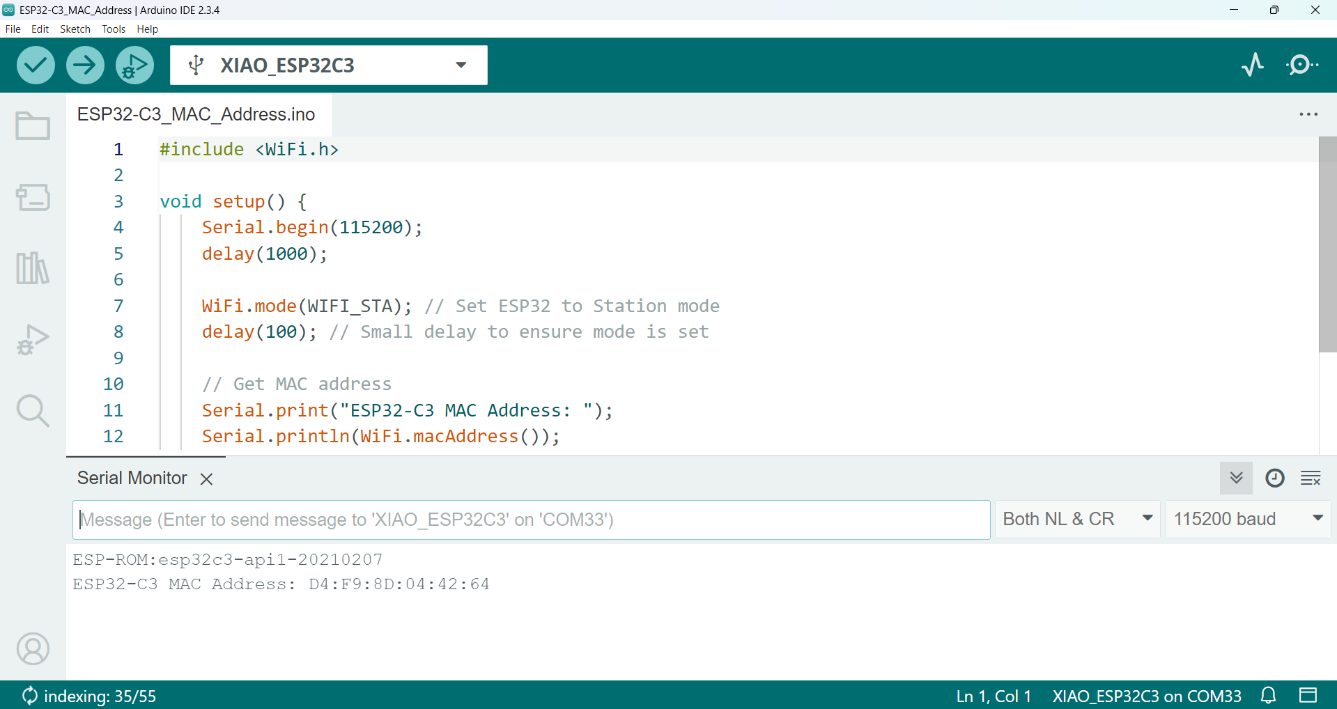
| MAC address finding. |
|
 |
|
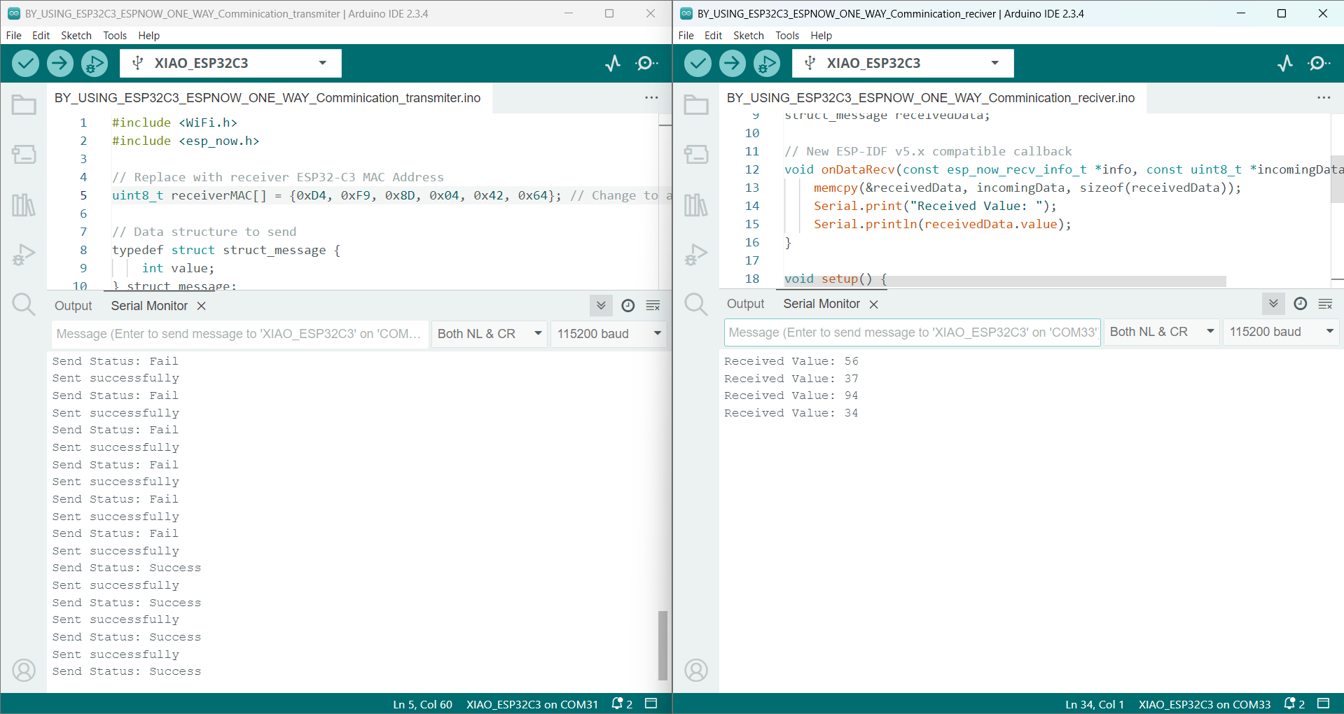
| Microntrollers connected with each other and sending deta. |
|
 |
|
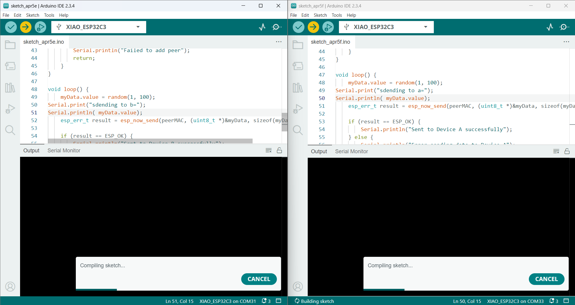
| Now compling final code for sensor |
|
 |
|
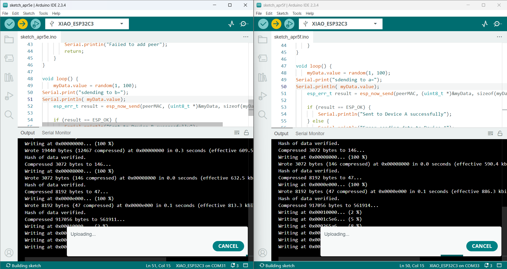
| Uploading final code for sensor |
|
 |
|
| Code uploaded successfully, and data is now visible on the Serial Monitor. |
|
 |
|
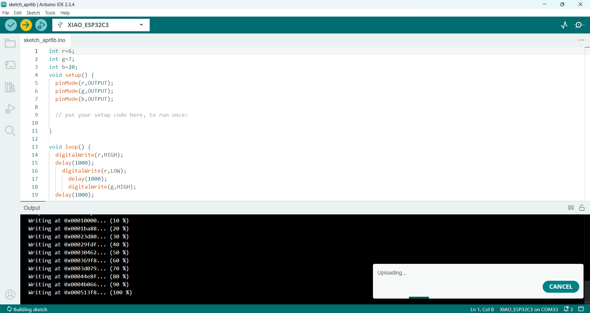
| Now compling final code for both Sound sensor and RGB LED. |
|
 |
|
| Uploading final code for both Sound sensor and RGB LED. LED. |
|
 |
|
| Code uploaded successfully, and data is now visible on the Serial Monitor. |
|
| |
|
| The RGB LED is functioning in response to the sound sensor through wireless communication. |
|
| Wireless communication using sound sensor and RGB LED has been successfully completed, and the result here. |
|
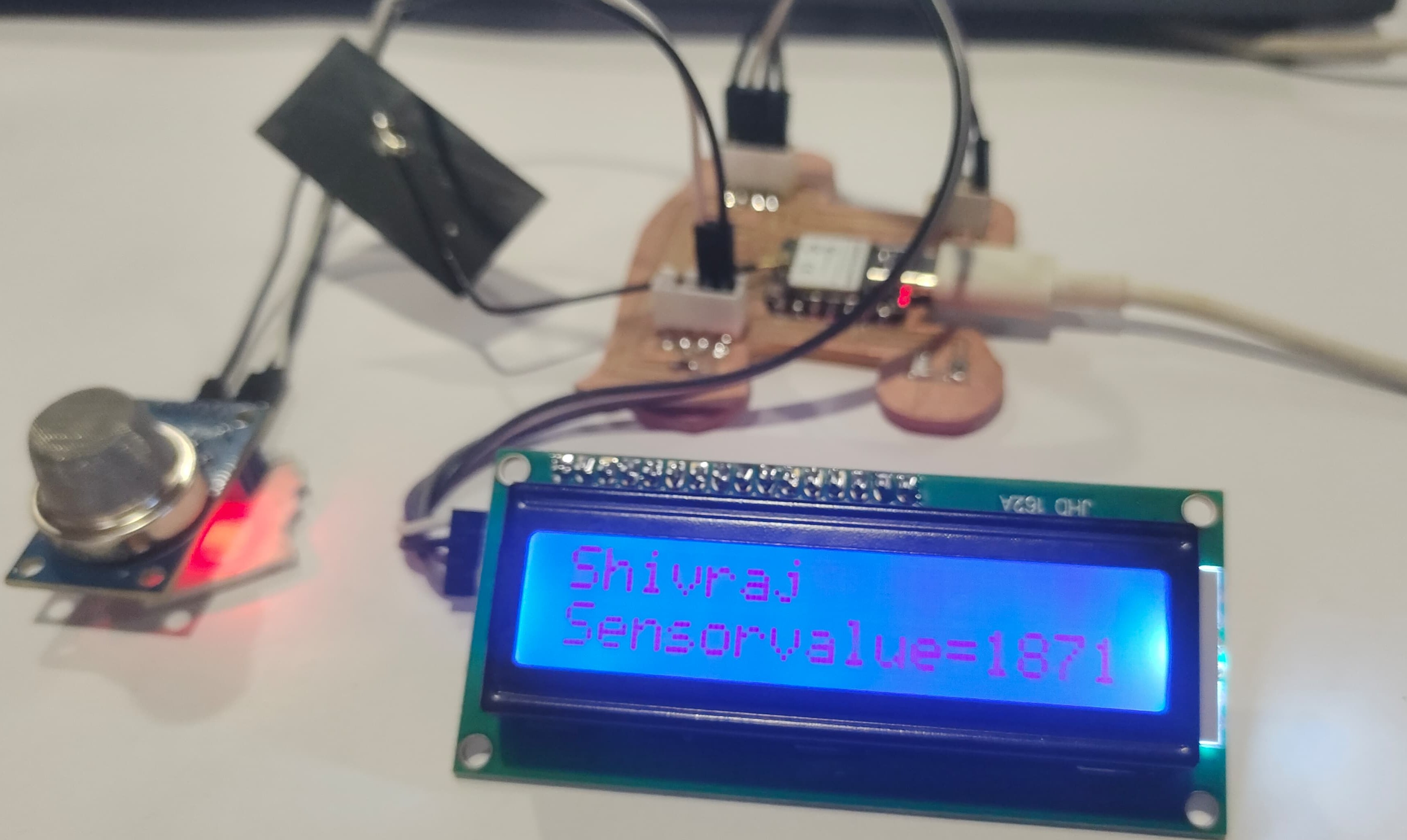
Cloud Communication - Smoke dedction sensor with LCD Display
 |
|
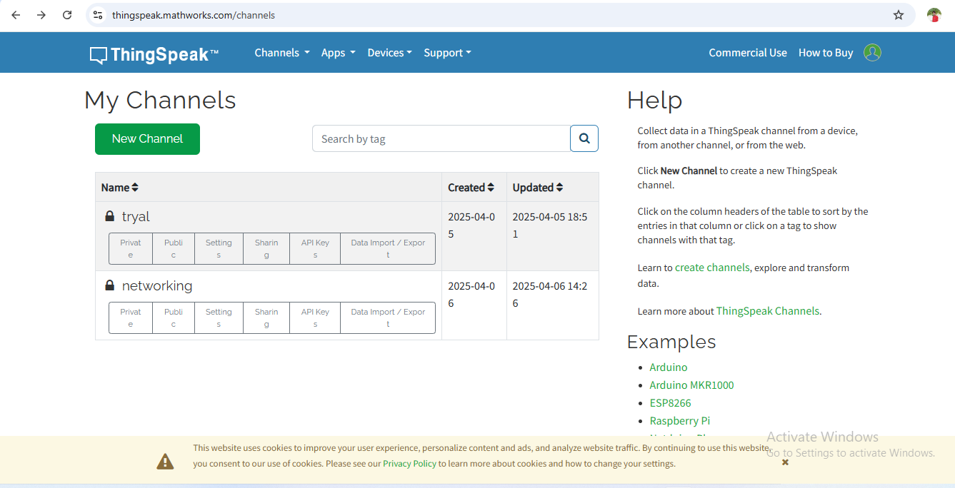
| First download Thingspeak software and create an account for login. |
|
 |
|
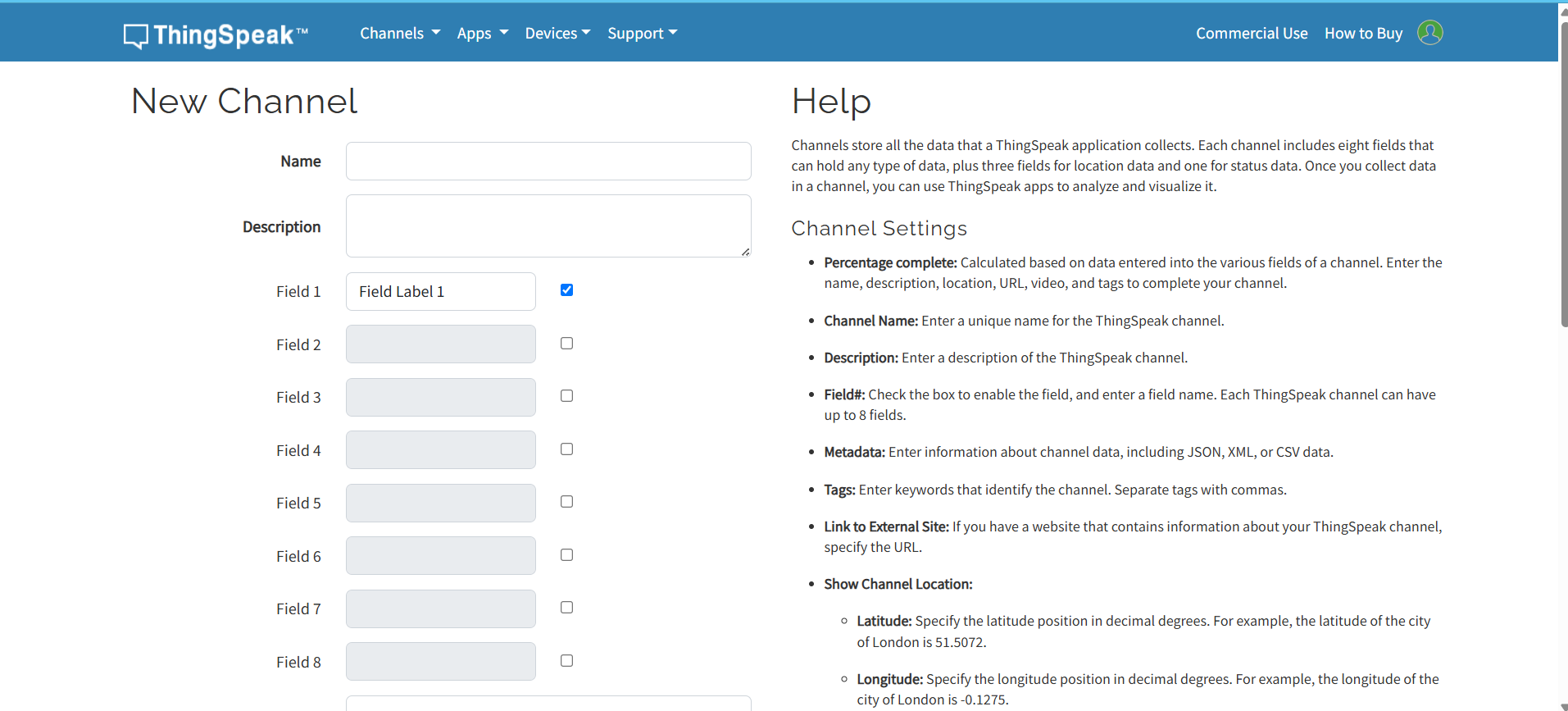
| Now click to new channel and make for showing real time data on thingspeak. |
|
 |
|
| Fill the information in the sections like channel name. |
|
 |
|
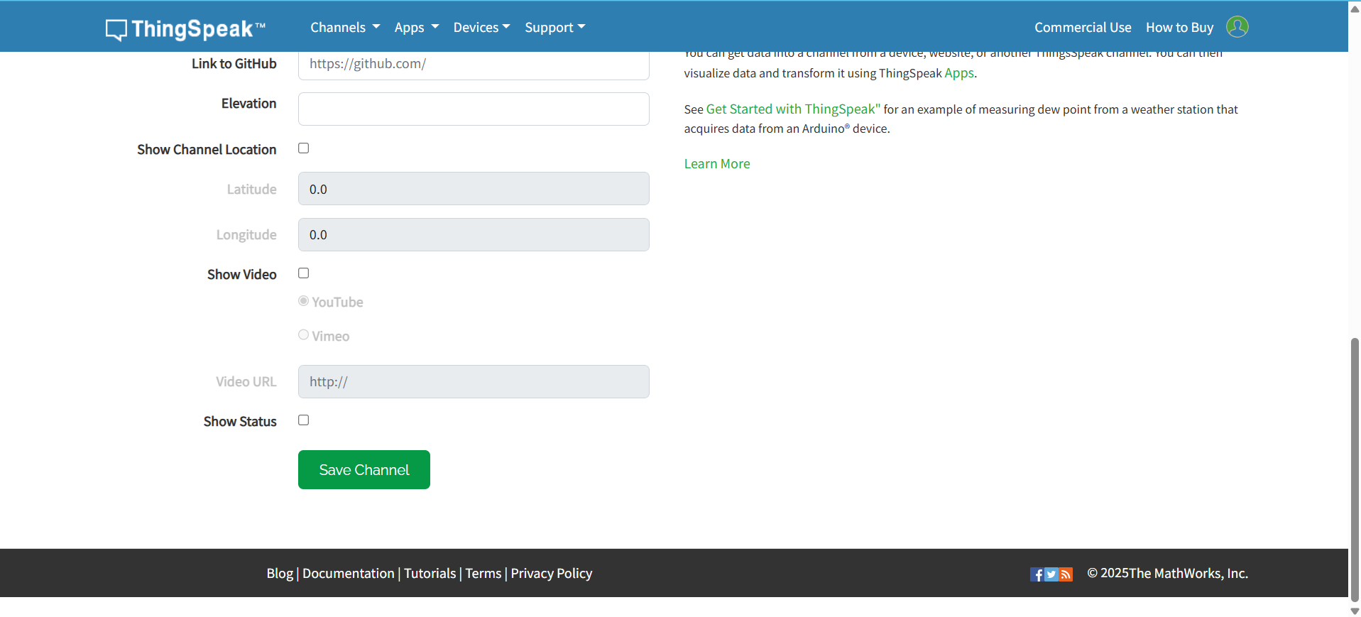
| And save the channel |
|
 |
|
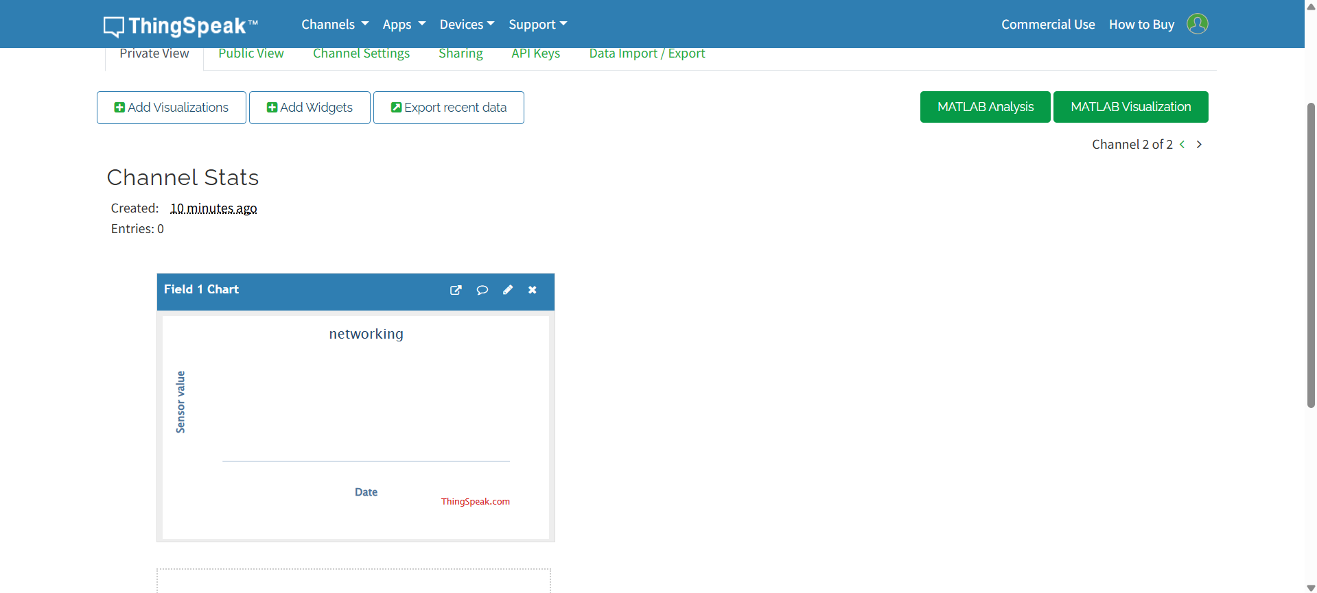
| The channel has been successfully created and is now visible on the portal. |
|
| |
|
| Smoke sensor and LCD display connected with microntroller |
|
 |
|
| Now compling the code for testing |
|
 |
|
| Uploading the code for testing |
|
 |
|
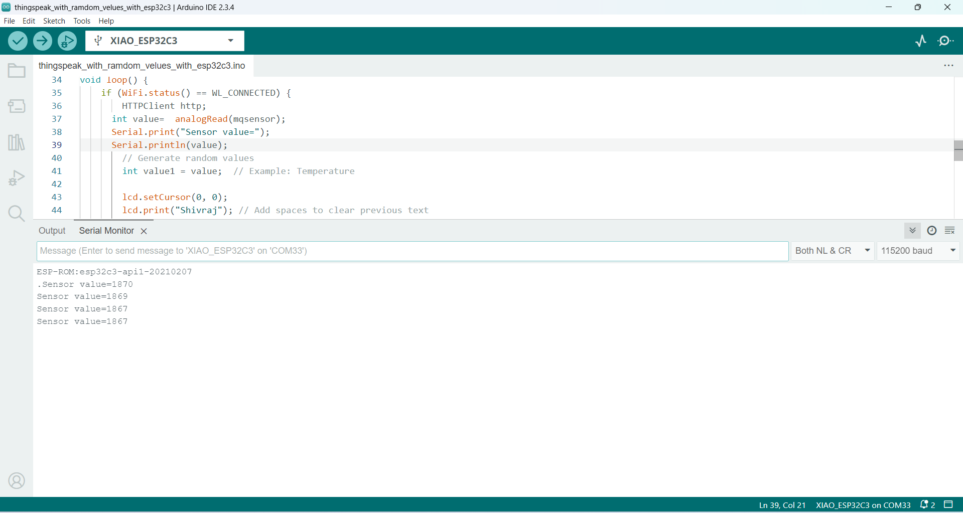
| Code uploaded and data showing on serial monitor. |
|
 |
|
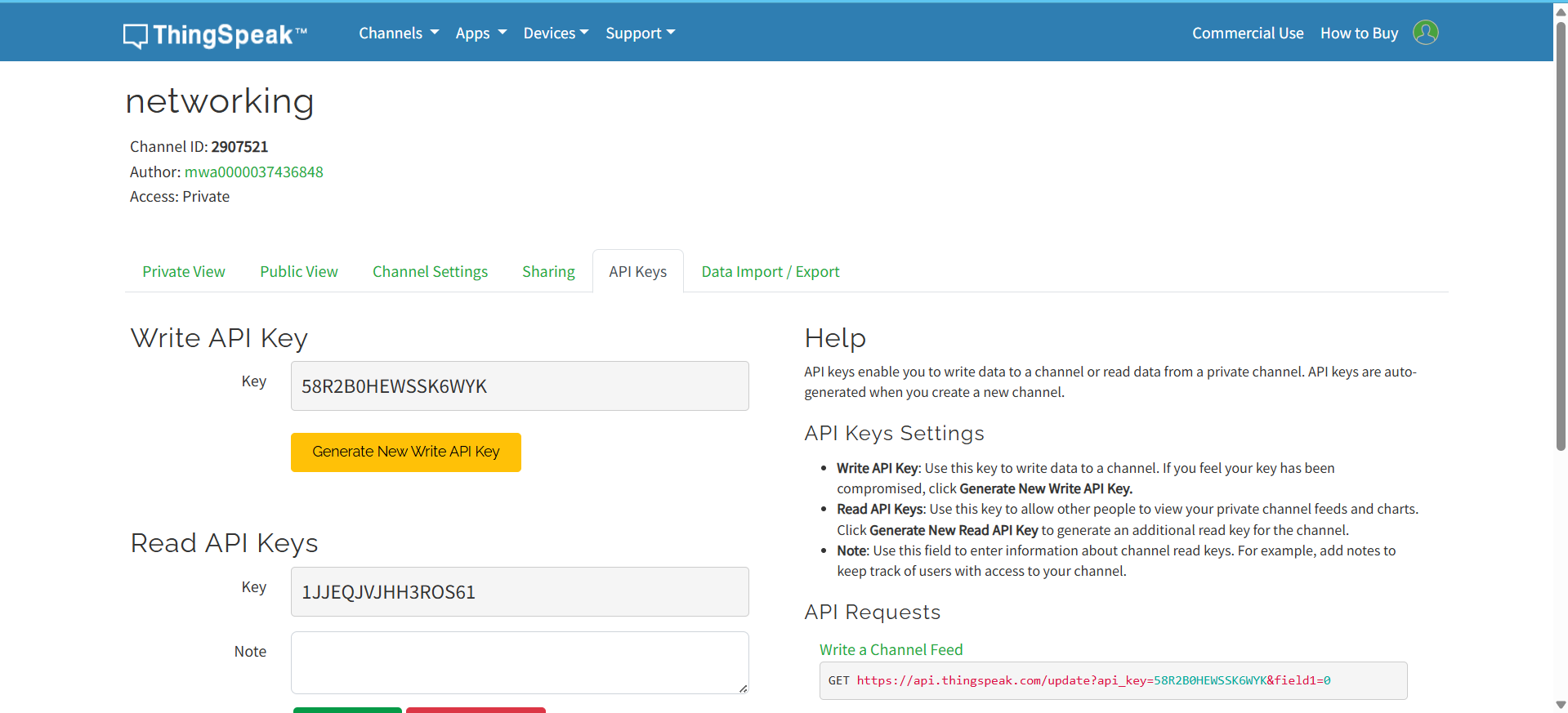
| KPI key is used for establishing a connection with cloud communication. |
|
 |
|
| Uploading the code with the KPI key to establish a connection with the cloud. |
|
 |
|
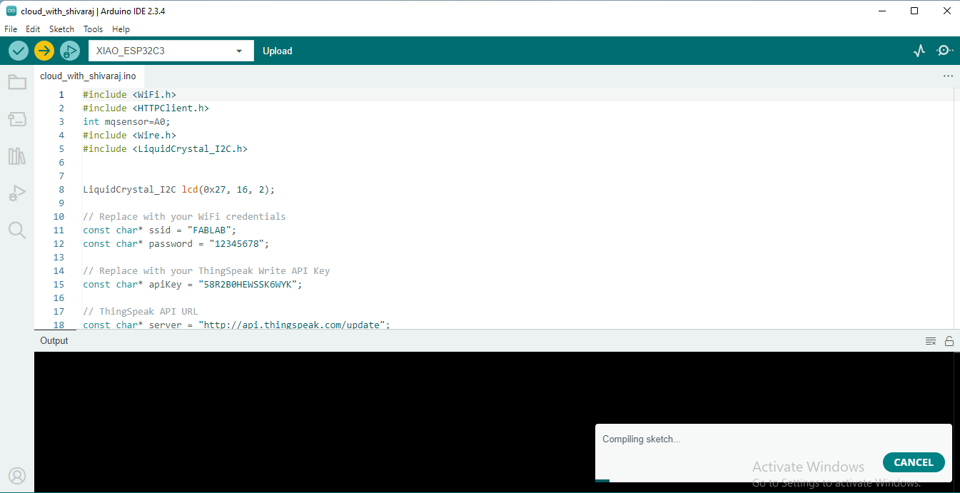
| Compiling and uploading the final code for smoke sensor and RGB LED |
|
 |
|
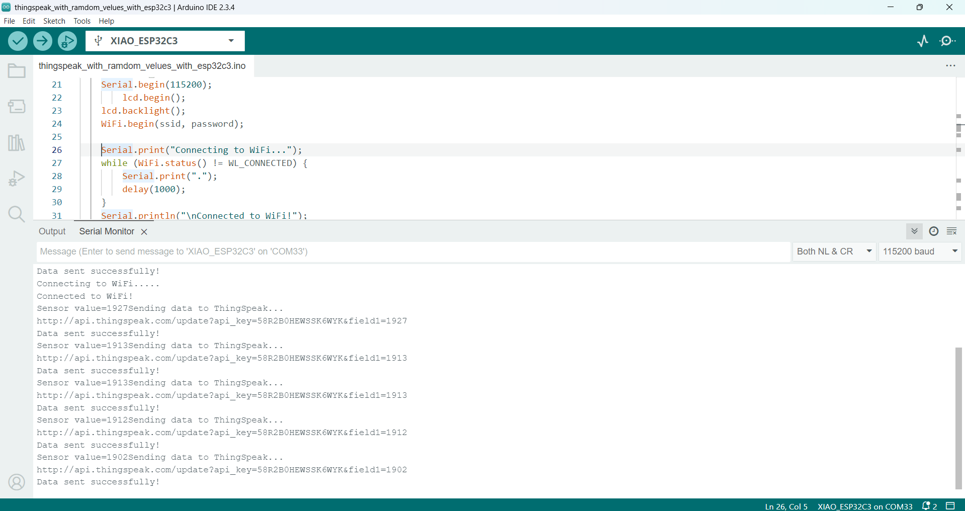
| Data has been successfully sent to the cloud, and the connection has been established. |
|
 |
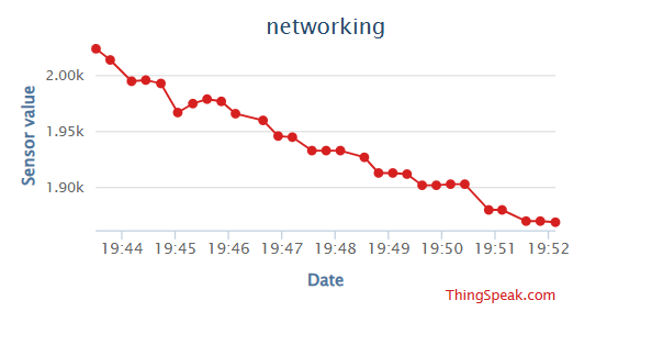 |
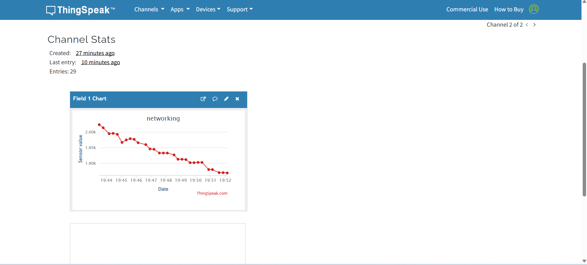
| Now the data is being displayed on ThingSpeak in a real-time graph. |
|
| Cloud communication using smoke sensor and LCD display has been successfully completed, and the result here. |
|
Original File Given Below -
Testing Code
Wired Communications Testing Code
Wireless Communications Testing Code
Cloud Communications Testing Code
Final Code
Wired Communication - IR sensor with LED
Wireless (WiFi) Communication - Sound Dedction sensor with RGB LED
Cloud Communication - Smoke detection sensor with LCD Display
Summary
This week, I learned how to do communication between multiple microcontrollers using different methods. I explored three types of communication: wired, wireless (Wi-Fi), and cloud-based communication.
All these examples demonstrated one-way communication, where data flows from one microcontroller to another in a single direction.
In the group assignment, we further extended our learning by implementing two-way communication between two microcontrollers, allowing both to send and receive data from each other in real time.
Conclusion
Through these hands-on experiments, I gained a solid understanding of how microcontrollers communicate using various protocols and mediums. It enhanced my practical knowledge of real-world applications in IoT systems, and strengthened my ability to design efficient communication systems using wired, wireless, and cloud technologies.