
About this week
This week, we explored output devices and learned how to integrate them with a microcontroller. We worked with servo motors, OLED displays, LCDs, and DC motors, successfully interfacing them with the microcontroller.
To validate their functionality, we monitored real-time data using the serial monitor and analyzed the readings. Additionally, we utilized graphical representations to visualize the data, allowing us to better understand the behavior and fluctuations of the output devices over time.
This hands-on experience strengthened our skills in output device interfacing, data acquisition, and visualization techniques, improving our ability to analyze and interpret system performance.
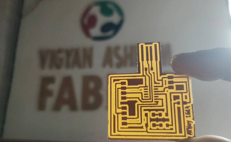
Heroshot of the Assignment
 |
 |
|
|
|
|
|
|
Objctive of the Assignment
1.Group Assignment -
2. Indivisual Assignment -
What is Output Device ?
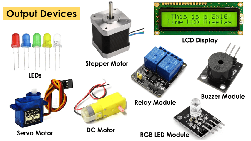
Output devices include components such as LEDs, buzzers, LCD displays, speakers, motors (DC, servo, and stepper), and relays. When these devices are connected to a microcontroller, they receive signals from it and perform specific actions, such as displaying information, producing sound, or controlling movement. This is why they are classified as output devices.
Type of Output Device
Website Reference here
Output Device
An output device is an electronic component that receives signals from a microcontroller or system and performs a specific action, such as displaying information, producing sound, generating motion, or controlling external devices. These devices are used in various applications, including automation, robotics, communication systems, and electronic devices.
 |
|
|
|
|
Individual Assignment
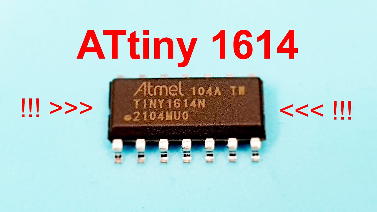
ATtiny 1614
ATtiny1614 is a low-power, high-performance 8-bit microcontroller from the AVR family, designed for embedded applications. It features tinyAVR architecture and is well-suited for small-scale projects requiring efficiency and minimal power consumption.
I used Attiny for my microcontroller.
 |
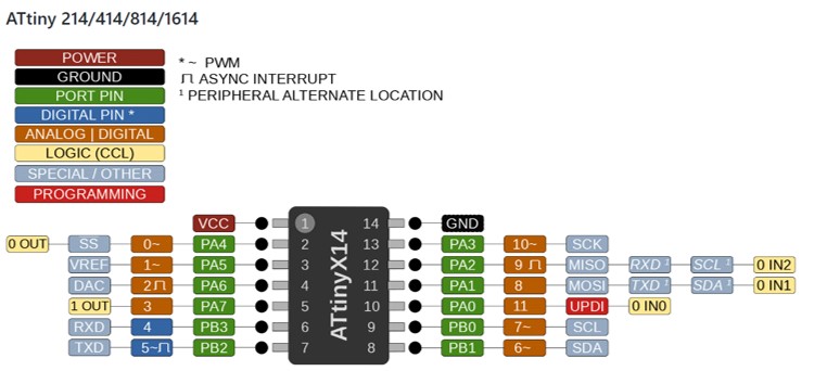 |
| ATtiny 1614 |
Pinout |
Website reference here
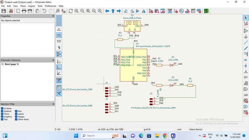
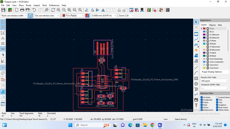
Designing a PCB for Output device in KiCad.
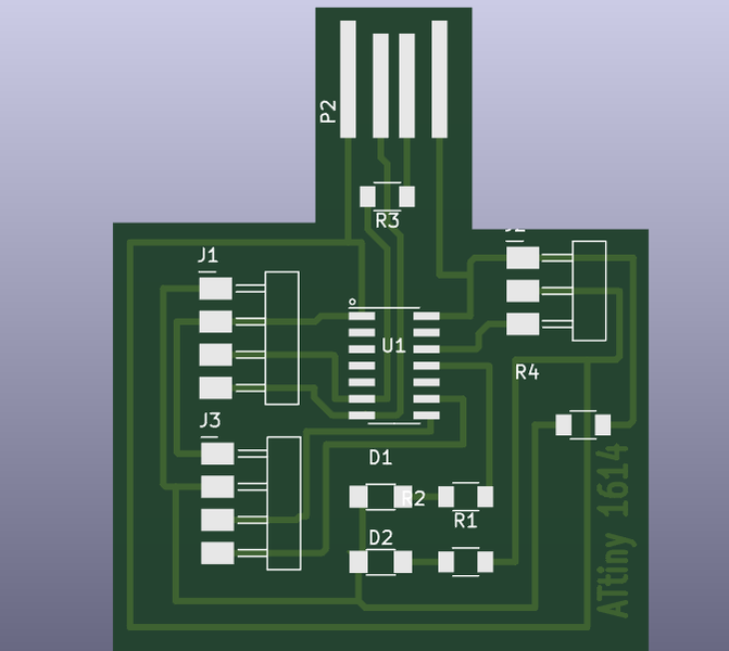
PCB - ATtiny 1614
 |
 |
| Creating the schematic design of the PCB. |
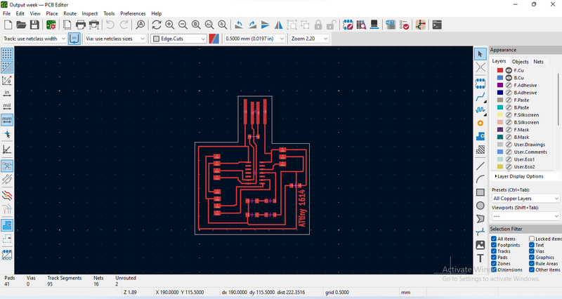
Tracing, edge cutting, and other such as component placement, routing, via optimization, and layer management. |
 |
 |
| edge cut completed |
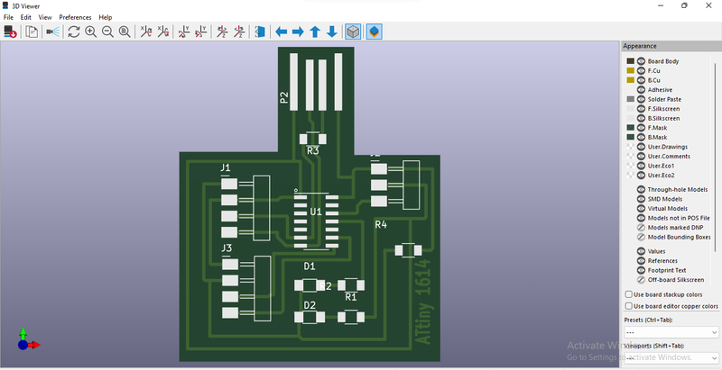
The PCB design is finally complete, and here is the 3D view. |
To see the entire process for designing, go through this assignments.
PCB Milling With SRM20
 |
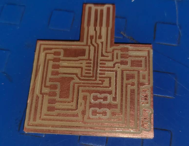 |
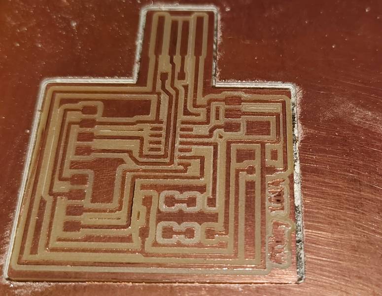
| PCB Milling Completed. |
Removed the PCB from Milling Machine |
To see the entire process for Milling PCB, tool path generate, go through this assignments.
Components Used
Output Device explored
 |
 |
| RGB LED |
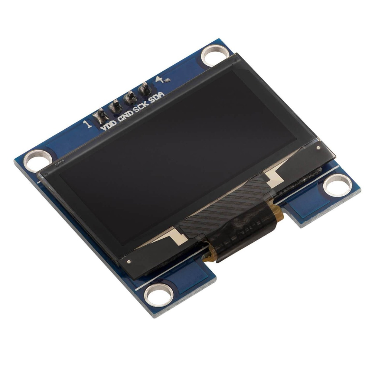
OLED Display |
RGB LED
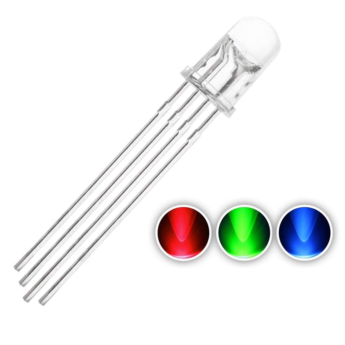
RGB LED - (Red, Green, Blue Light Emitting Diode) is a special type of LED that can produce a wide range of colors by combining different intensities of red, green, and blue light. It is commonly used in decorative lighting, displays, and indicator systems.
Type of RGB LED
Uses of RGB LED
Pinout of RGB LED
OLED Display
OLED (Organic Light Emitting Diode) is a self-emissive display technology that produces light without the need for a backlight. It provides high contrast, low power consumption, and excellent color quality, making it ideal for compact electronic displays.
Type of OLED
Uses
Pinout
Reference Website here
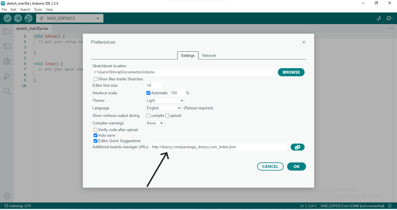
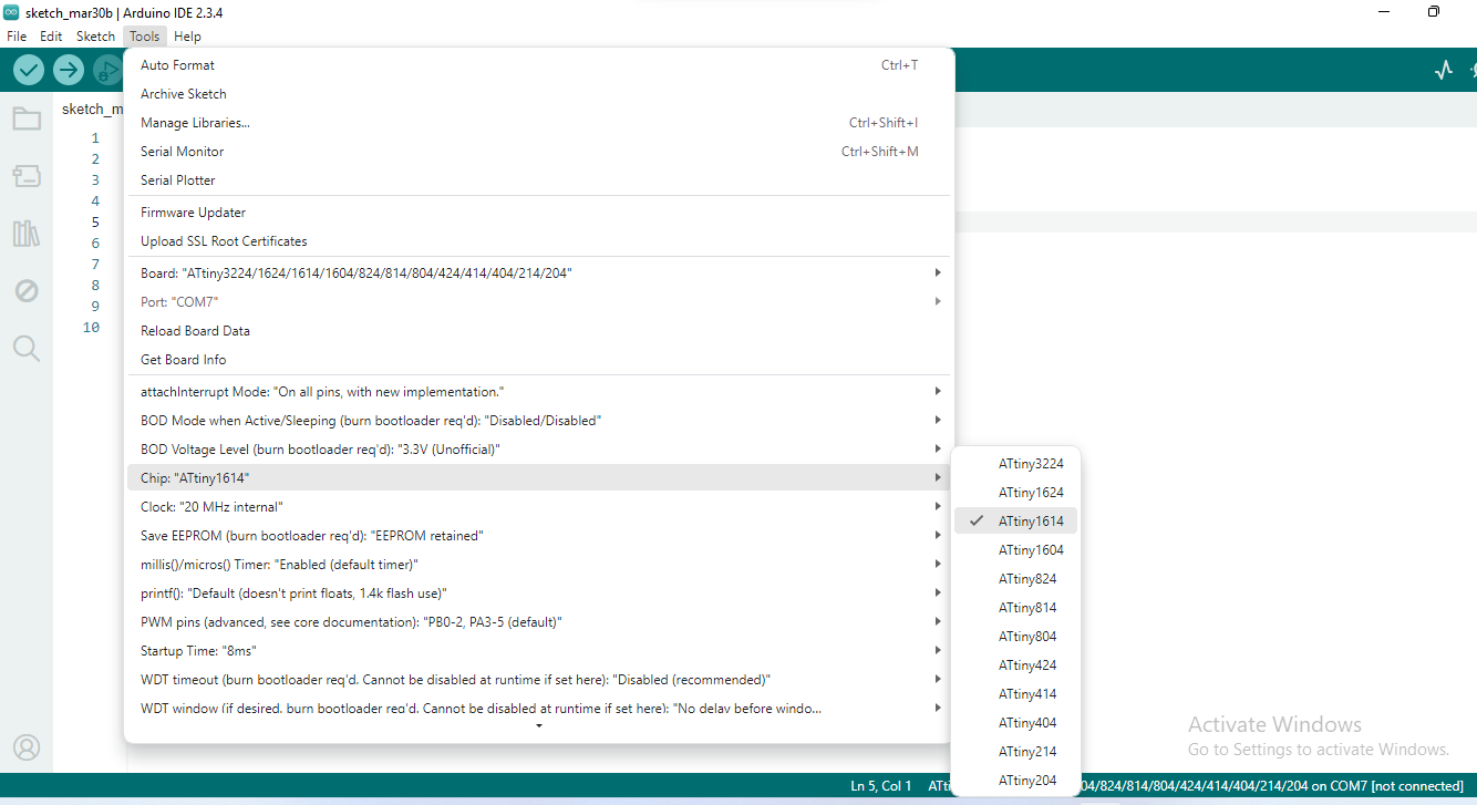
ATTiny 1614 installation process
 |
|
| First open Arduino , go to file and select the references. After that put this URL- "http://drazzy.com/package_drazzy.com_index.json" in additional boards manager |
|
 |
|
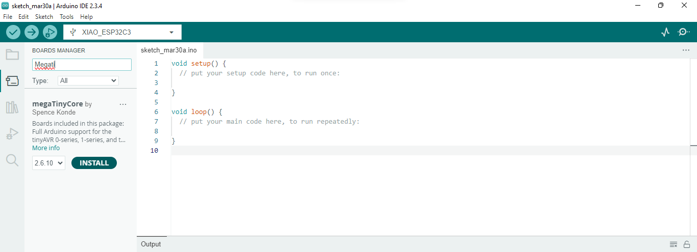
| Now click on board managar and search - megaTinyCore and install it. |
|
 |
|
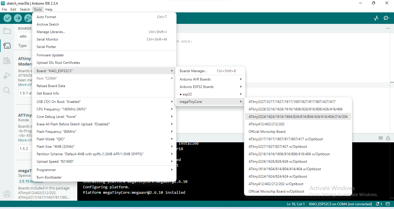
| After installing the MegaTinyCore, go to Tools > Board> MegaTinyCore, and then select ATtiny1614. |
|
 |
|
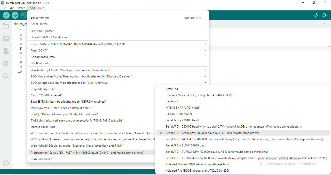
| Next, go to Tools > Chip - and select ATtiny1614. |
 |
|
| Then, go to Tools > Programmer, and select - Serial UPDI 4.5V - 460800 baud (CH340 or other compatible options). |
|
Programming the board
Step By Step Process
RGB LED
 |
|
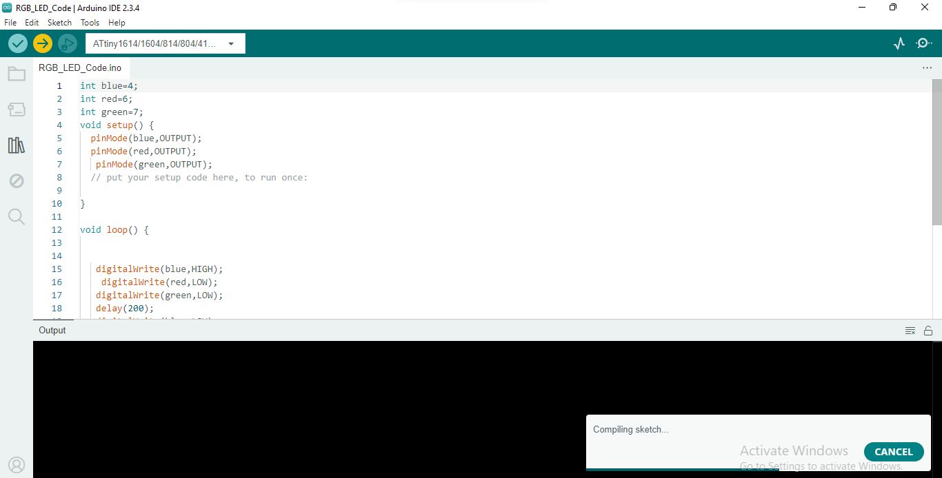
| Writing Code and Uploading |
| > | |
| RGB LED Working successfully |
OLED Display
 |
|
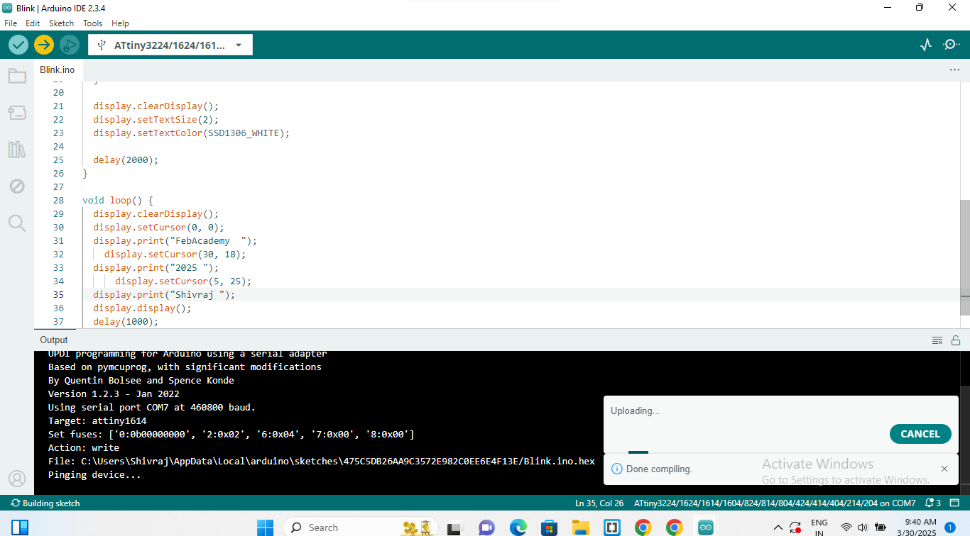
| Writing Code and Uploading |
| > | |
| OLED Working successfully |
Original File Here
RGB LED Code here
OLED Display Code here
Kicad PCB design File in PNG formet
Trace cut File here
Edge Cut File here
Kicad PCB design File in "rml" formet
Trace cut File here
Edge Cut File here
Conclusion
This week, we explored various output devices, including servo motors, relay modules, stepper motors, RGB LEDs, and OLED displays. These devices fall under the category of output components as they receive signals from a microcontroller to perform specific functions.
To understand their functionality, we connected them to a microcontroller, programmed them accordingly, and successfully tested their operation. I specifically used ATtiny1614 microcontroller to control an RGB LED and an OLED display, and both devices functioned perfectly as expected.
Through this hands-on experience, I gained valuable insights into interfacing and controlling output devices using microcontrollers, reinforcing my understanding of embedded systems and electronics.