Learning Experience
Wildcard Week provided me with a valuable opportunity to explore digital fabrication processes beyond those covered in other assignments. I chose to work with computerized embroidery using the Usha Janome Memory Craft 450E and CNC plasma cutting using FastCAM software—two very different digital fabrication tools. Both offered deep insights into the integration of design, software, and machine operation.
Task: Wildcard Week
Design and produce something with a digital process (incorporating computer aided design and manufacturing) not covered in another assignment, documenting the requirements that your assignment meets, and including everything necessary to reproduce it. Possibilities include but are not limited to
Designing in CorelDRAW
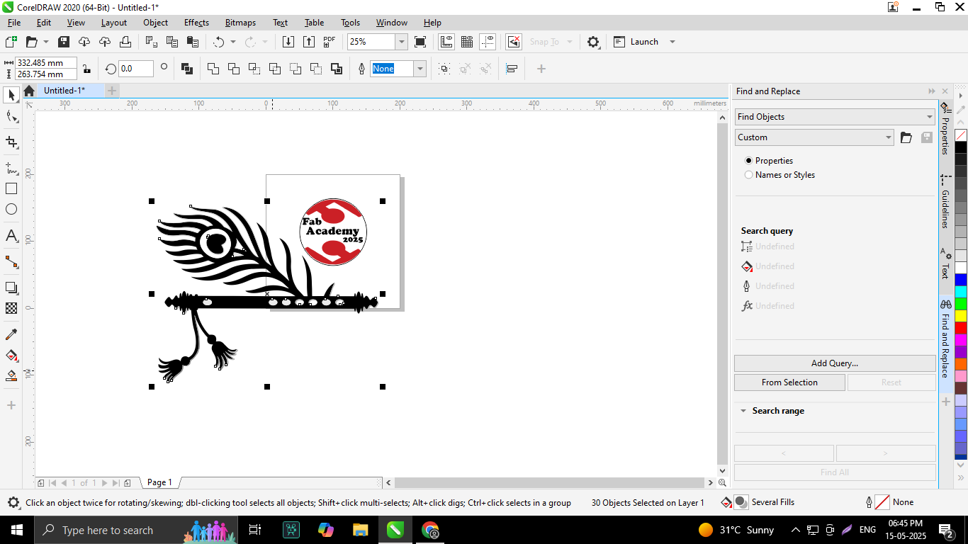
First, I created my design using CorelDRAW. I thought it would be better to modify the Fab Lab logo slightly and make a unique design of my own. This way, I could prepare the design accurately and use the sewing machine to bring it to life.
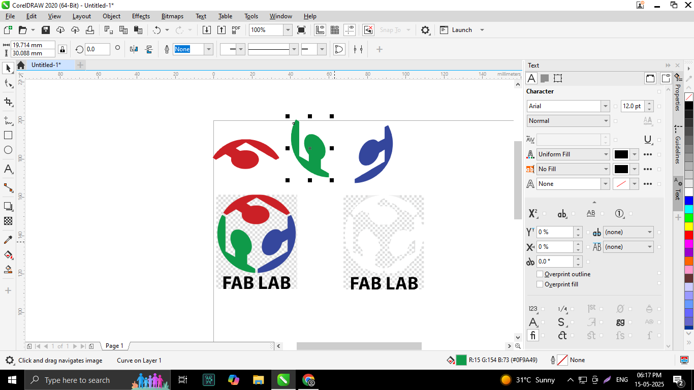
First, I imported the images into CorelDRAW and used the Bitmap Trace feature to convert the images into vector format. After tracing, I ungrouped the traced elements and grouped the required parts. This grouped graphic became the core component of my logo.
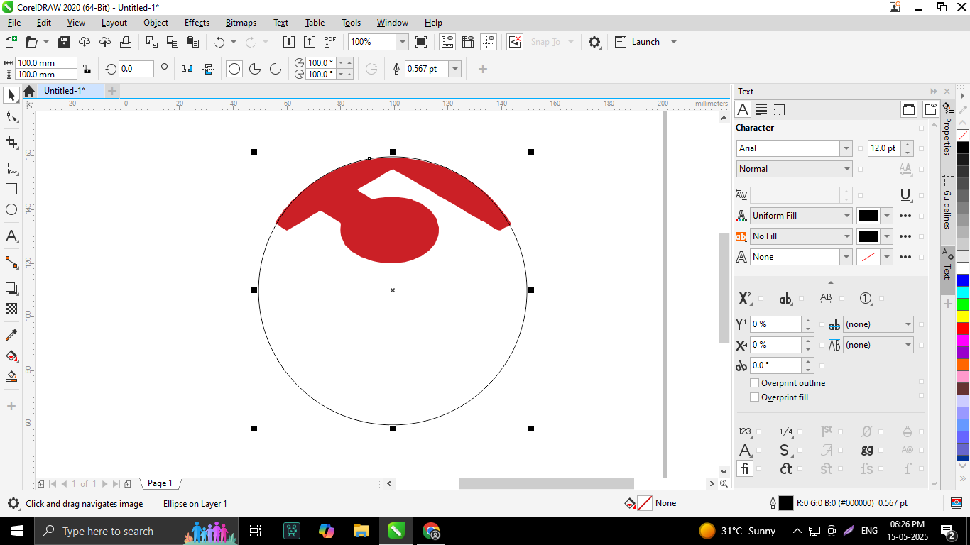
Then, I created a perfect circle around the grouped design elements. Inside this circle, I placed a text element at the top to enhance the overall design.
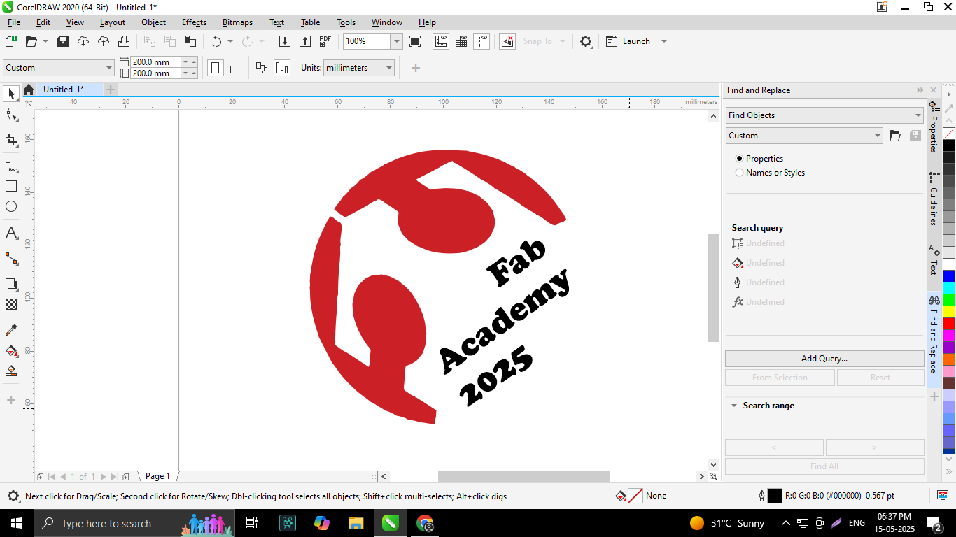
Next, I duplicated the text and edited it to read “Fab Academy 2025.” I aligned this text carefully with the graphic to ensure balance and clarity.
After that, I arranged the text layers by placing some text above and below, with “Fab Academy 2025” positioned in the center. This layering made the logo more visually appealing.
I then added a flute illustration beside the grouped design elements to incorporate an artistic and symbolic touch.
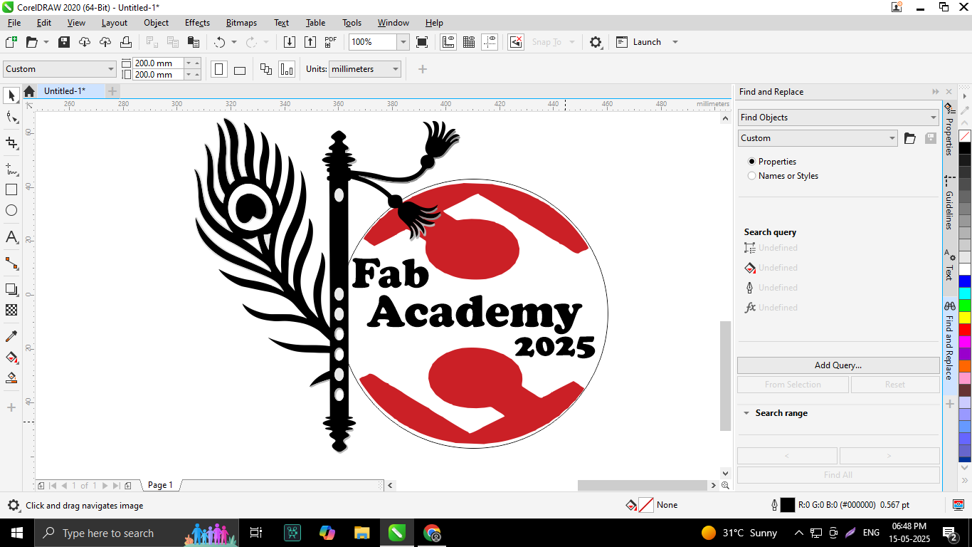
The flute was positioned standing upright on the left-hand side of the design elements, creating a harmonious and balanced composition.
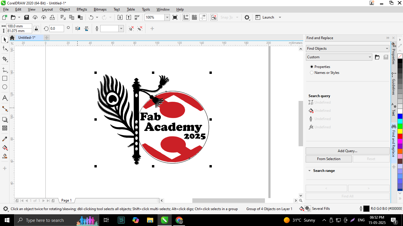
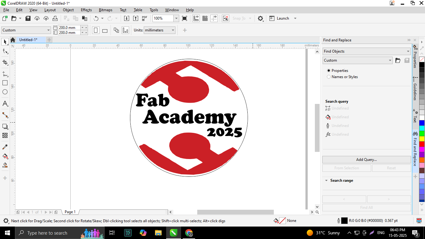
Finally, my logo design was complete, and I exported it in multiple formats including CDR, PDF, PNG, and JPG for flexible use across different platforms.
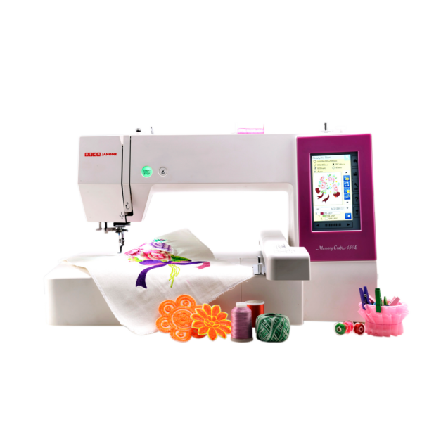
Designed for home business owners, embroidery aficionados, and creative professionals, the Usha Janome Memory Craft 450E is a high-performance computerized embroidery-only machine. The 450E offers both accuracy and simplicity with its large 200 x 280 mm embroidery area and cutting-edge features, including an automatic thread cutter, full-color LCD touchscreen, and USB import capability.
This machine lets customers easily customize their works with its 160 built-in embroidery designs and 6 monogramming fonts. Complete control over every design is provided by its user-friendly on-screen editing capabilities, which include rotate, resize, mirror, and color edit. Additionally, automatic thread sensors guarantee uninterrupted, seamless functioning.
The Memory Craft 450E blends creativity with user-friendliness, making it a great option for producing complex embroidery on clothing, home décor, and personalized gifts. It is perfect for both novice and expert users.
Usha Janome Memory Craft 450E – Specifications
| Category |
Details |
| Model Name |
Usha Janome Memory Craft 450E |
| Machine Type |
Computerized Embroidery Machine (Embroidery only) |
| Display |
Full-color LCD touchscreen |
| Embroidery Area |
200 mm x 280 mm (7.9” x 11”) |
| Built-in Designs |
160 embroidery designs |
| Built-in Fonts |
6 embroidery fonts for monogramming |
| Design Format |
.JEF (Janome Embroidery Format) |
| USB Port |
Yes (for importing embroidery designs) |
| Maximum Speed |
860 stitches per minute |
| Thread Cutter |
Automatic |
| Thread Sensor |
Yes – alerts for thread breakage |
| On-screen Editing |
Rotate, Resize, Combine, Drag & Drop, Flip, Arc Text, Color Edit |
| Hoop Sizes Supported |
RE28b, SQ20b, RE20b, SQ14b, and Free Arm hoops |
| Included Accessories |
Hoop, needles, bobbins, thread guide, power cord, USB cable |
| Bobbin Type |
Top-loading, full rotary hook |
| Lighting |
Bright LED lighting |
| Weight |
Approx. 11.5 kg |
| Warranty |
Usually 2 years (verify with dealer) |
Janome’s state-of-the-art embroidery software, Artistic Digitizer version 1.7, is designed to function seamlessly on both Windows and macOS platforms. This versatile program caters to users of all skill levels by offering an intuitive interface alongside a comprehensive suite of advanced tools that simplify the creation, editing, and customization of intricate embroidery designs.
Key Features of Artistic Digitizer v1.7
- Cross-Platform Support: Fully compatible with Windows operating systems from version 7 through 11, as well as macOS versions ranging from Mojave (10.14) to Sequoia (15.3), ensuring broad accessibility for diverse users.
- Versatile Design Tools: Equipped with powerful functions such as rotate, resize, combine, drag-and-drop, flip, arc text, and comprehensive color editing options that empower users to precisely tailor their embroidery creations.
- PaintStitch Technology: Transforms ordinary images into stunning embroidery designs by replicating a painted canvas effect, adding a unique artistic flair to the stitched output.
- Couching Technique: Enhances embroidery projects by securely stitching down threads or yarns onto fabric, creating added texture and dimensionality.
- Extensive Design Library: Provides an abundant collection of built-in designs and font styles, perfect for monogramming and personalizing projects with ease.
- On-Screen Editing Tools: Allows detailed adjustments and refinements directly within the software’s interface, streamlining the design workflow without the need for external tools.
I utilized this software to generate the precise G-code required for fabric designs, facilitating seamless integration with embroidery machines.
To begin my design process, I launched the Artistic Digitizer v1.7 software by clicking its icon, which initialized the program and prepared the workspace for new embroidery projects.
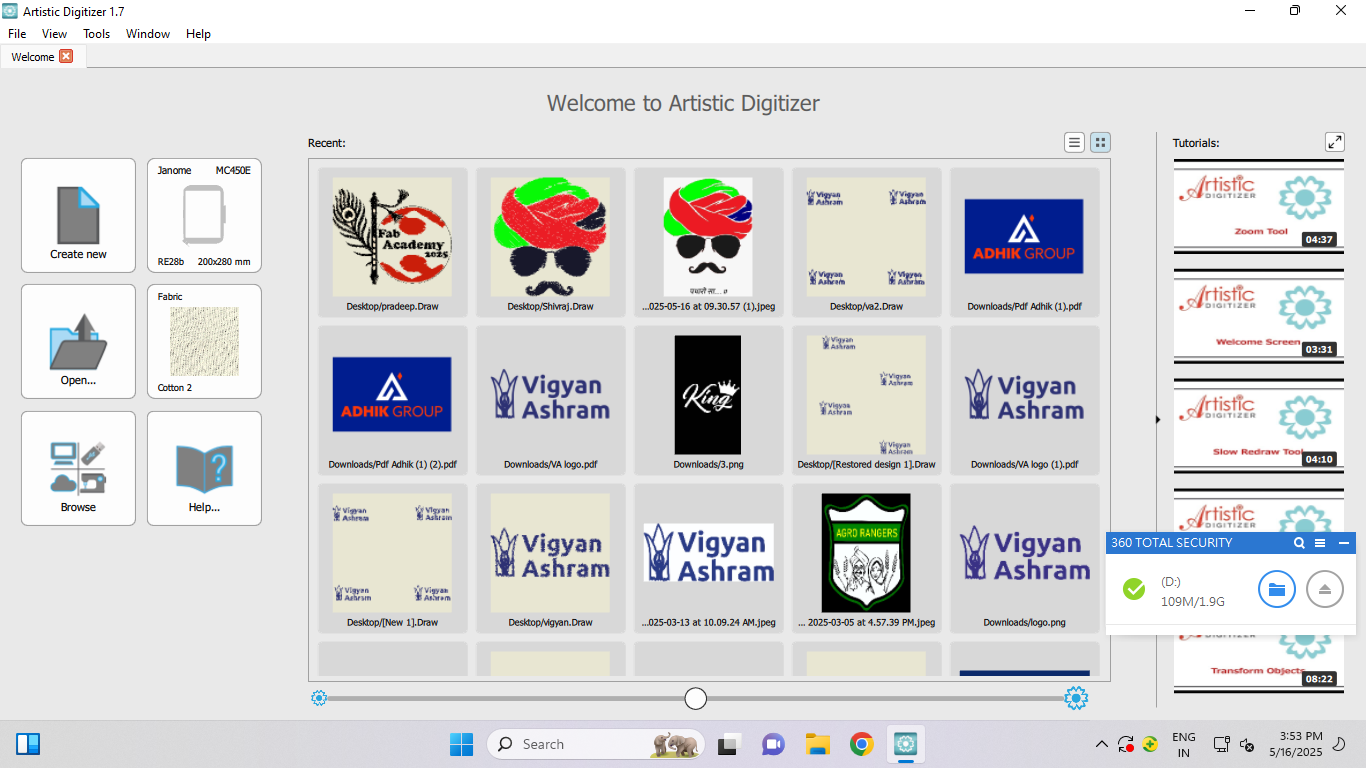
Upon opening the software, I selected the "Create New" option to initiate a fresh project, allowing me to start designing from a blank canvas.
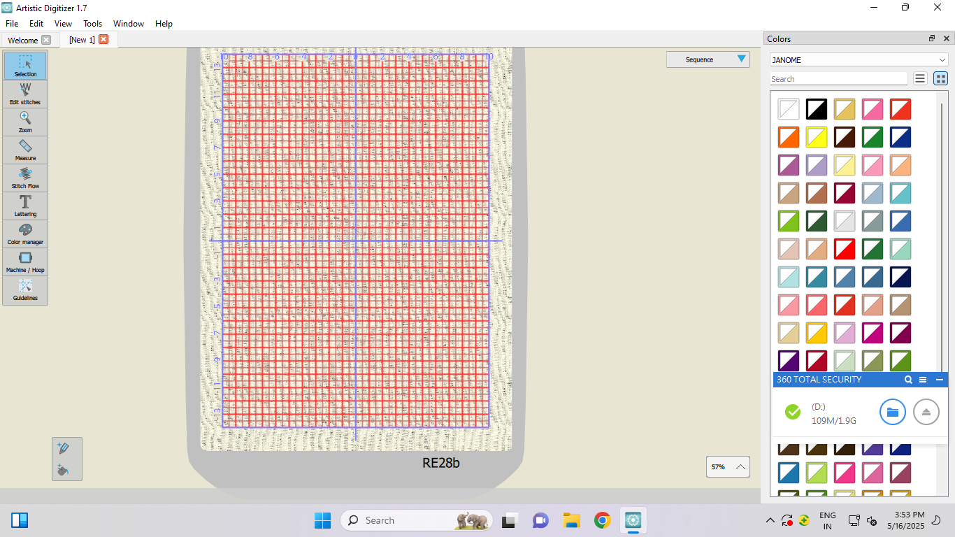
The main interface then appeared prominently, showcasing a user-friendly layout enriched with a broad spectrum of color palettes and customization features, making it easy to tailor designs according to specific requirements.
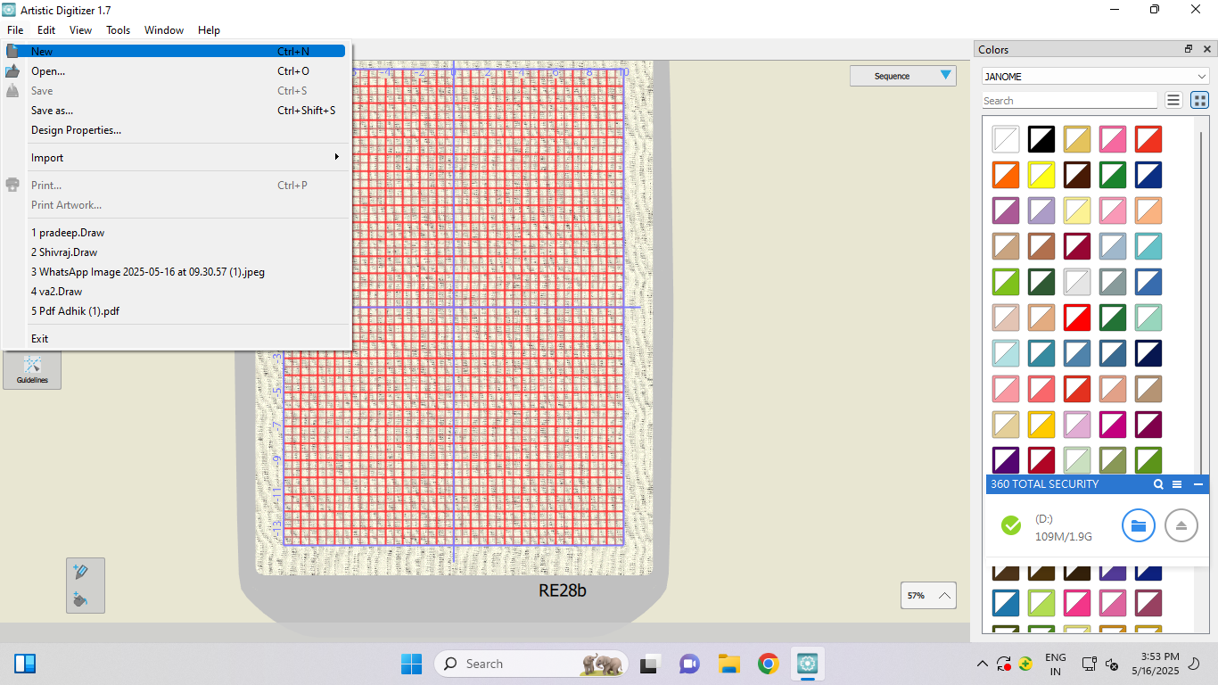
Next, I navigated to the "File" menu on the toolbar, which houses essential functions such as importing, saving, and exporting design files.
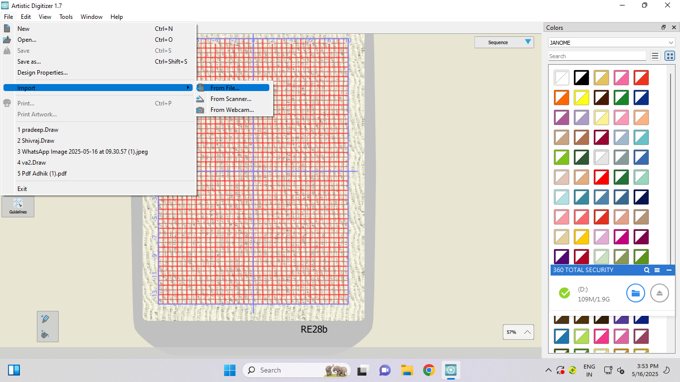
From the dropdown, I chose the "Import" option, specifically selecting "From File" to bring in an external design I had prepared earlier.
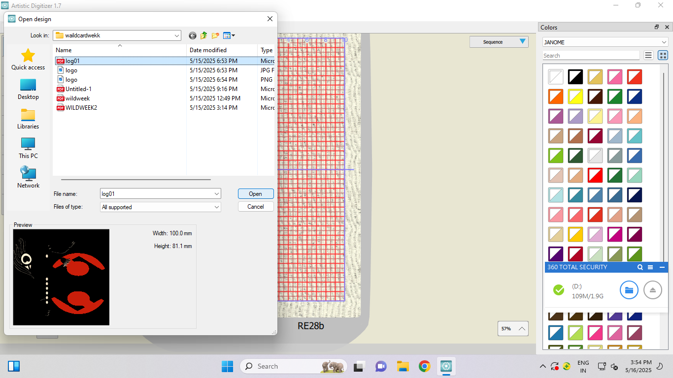
I then inserted my USB pen drive into the computer, accessed it via the file explorer window, and located the desired logo design saved in PDF format. Clicking on the PDF file and hitting "Open" imported the image into the software’s workspace.
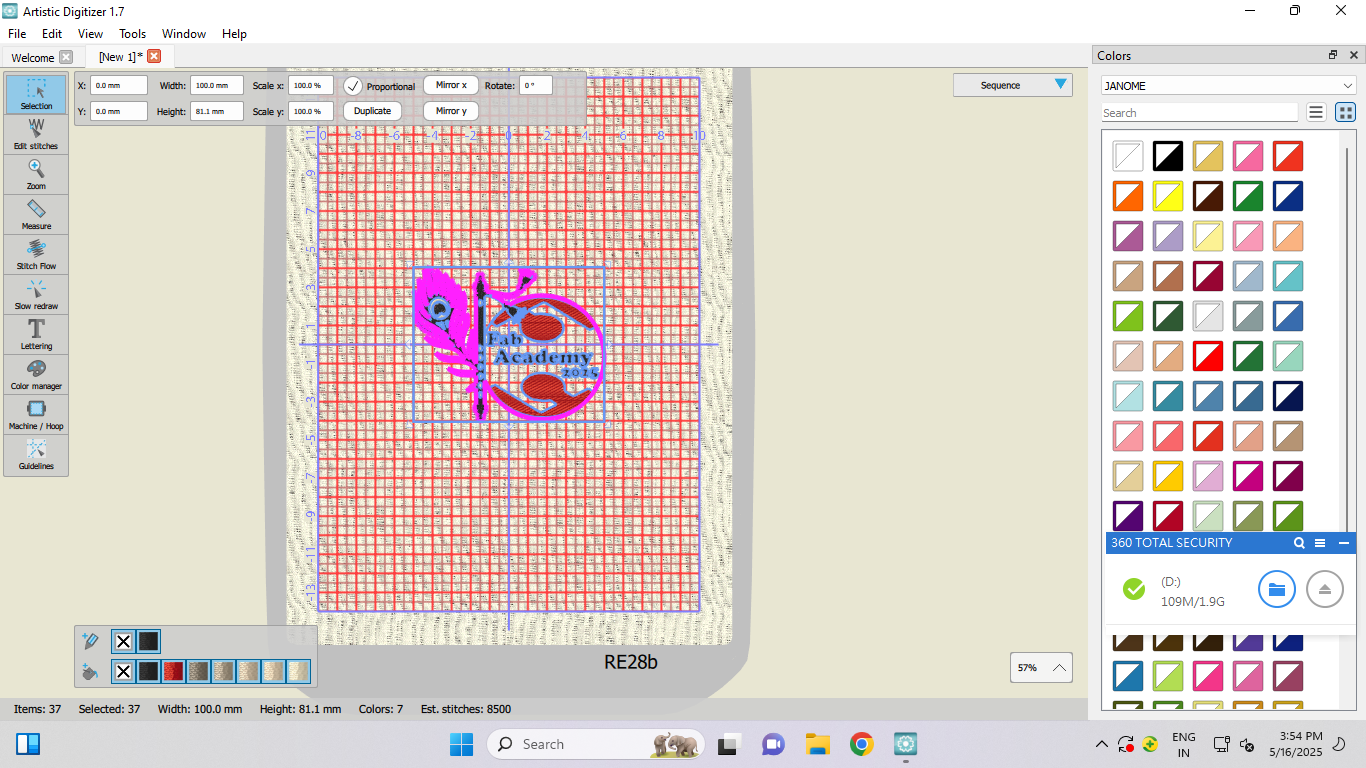
Once the logo was loaded into the working frame, I carefully reviewed it and made several adjustments to optimize its appearance. This included resizing the logo to the required dimensions, repositioning it accurately along the X and Y axes for ideal placement, and applying color fills to enhance its visual appeal.
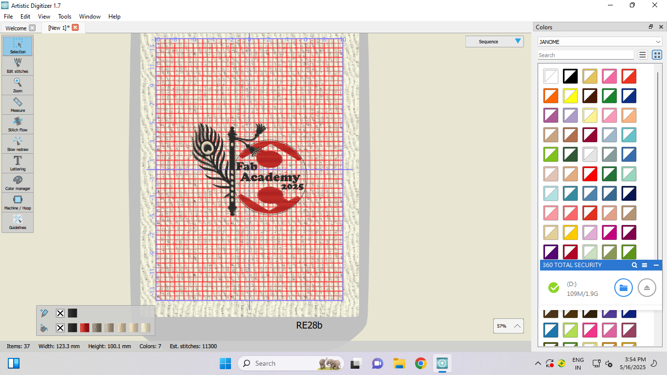
After finalizing all necessary refinements, I confirmed the logo was ready and proceeded to generate the corresponding embroidery code essential for the stitching process.
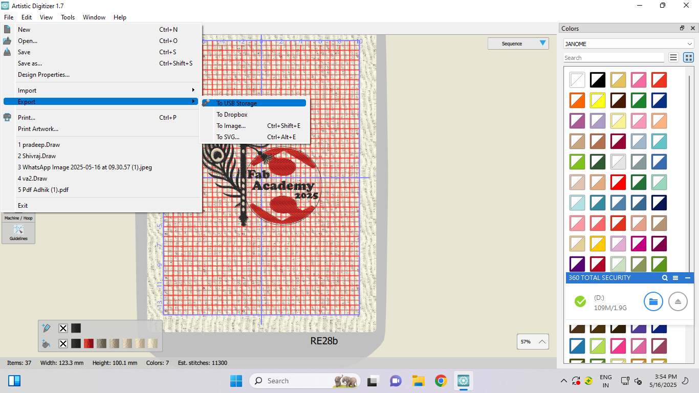
Returning once again to the "File" menu, I selected the "Export" function to save the finished design in a format compatible with the embroidery machine.
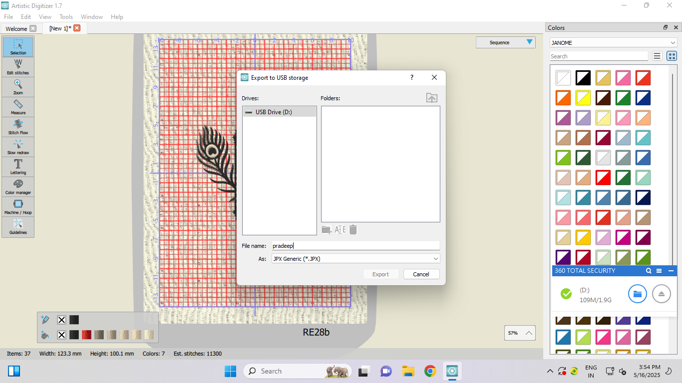
By choosing my USB storage device as the export destination, I ensured the design file could be effortlessly transferred and used directly with the embroidery equipment. I saved the generated embroidery code in JPX format, naming the file "Pradeep" for easy identification, thereby completing the entire design preparation and export workflow successfully.
After completing the setup of the machine, I proceeded to switch on its power. Following this, I configured the frame settings according to the requirements. To set the frame properly, I first placed the fabric in the embroidery frame. Once the fabric was securely fitted, I carefully attached the frame to the designated hooks on the machine. After ensuring everything was properly aligned, I turned on the power button of the machine. A small display screen lit up, indicating that the machine had successfully powered on. Next, I inserted the USB drive into the machine to upload the desired design file for further processing.
After the code is fully prepared, I power on the machine. Once the machine is switched on, I insert the pen drive into the machine. The entire process of this step is demonstrated clearly in the video.
The machine began operating exactly as I had envisioned and designed it, successfully executing the intended functions.
The machine was operating very smoothly and efficiently without any interruptions.
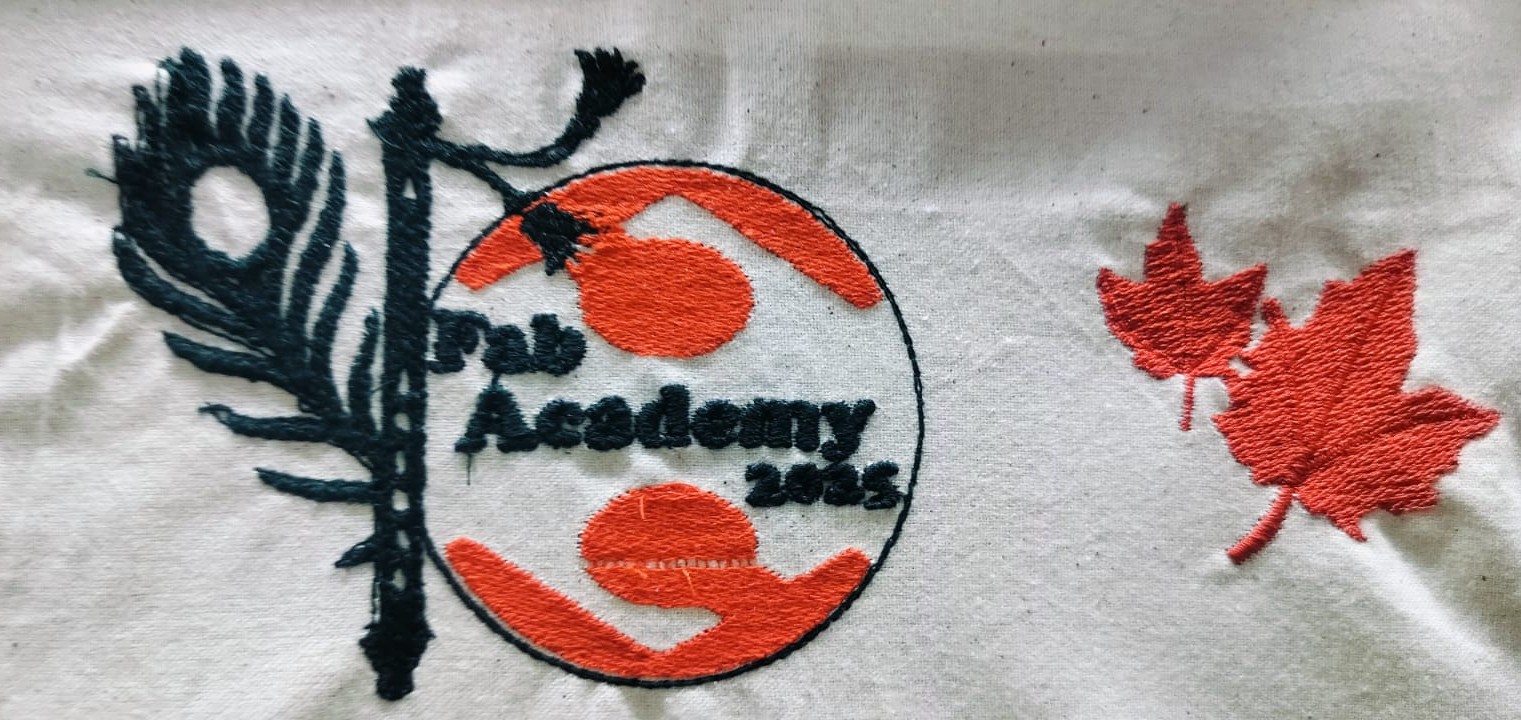
Final Object
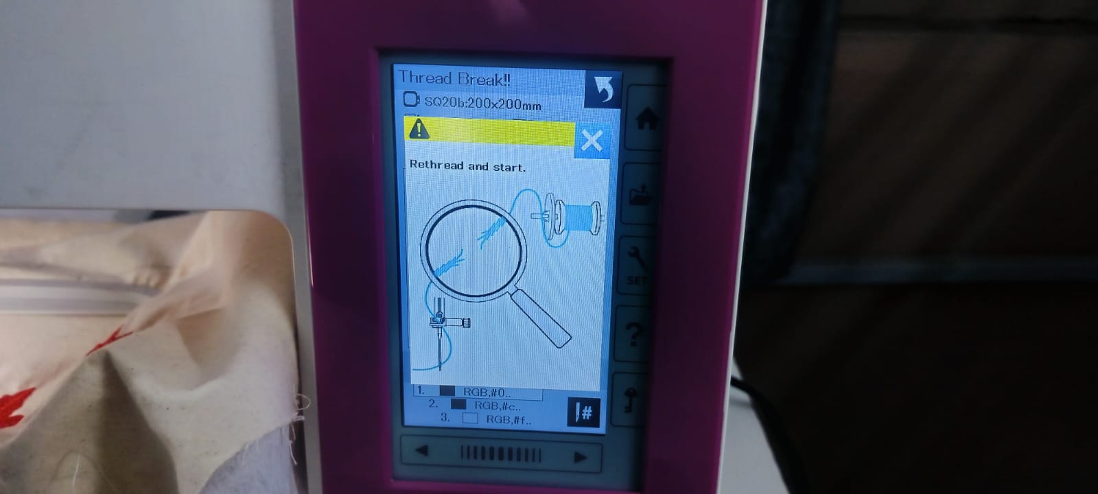
Thread Breakage Issue During Machine Operation
While operating the machine, I encountered frequent thread breakages because the thread quality was poor and not strong enough. Every time the machine was running smoothly, the weak thread would snap unexpectedly. As a result, I had to repeatedly stop the machine and reattach or replace the thread to continue the operation.
Plasma Cutting Machine
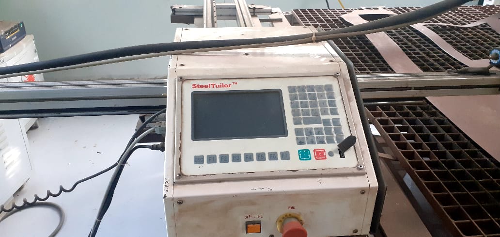
In our Fab Lab at Vigyan Ashram, we use the SMART III Portable CNC Plasma Cutting Machine. Designed with the F4 concept—easy to transport, install, operate, and maintain—this machine is well-suited for fabrication work in educational and research settings.
It features a working area of 1500 mm x 3000 mm and a precision table structure. The dual-drive system provides stability and allows for the handling of heavier materials. With high-precision dual-shaft linear guides, the machine ensures accurate and efficient cutting performance. The structural design is a perfect balance of strength and portability.
Technical Specifications
| Specification |
Details |
| Model |
SMART III |
| Input Voltage |
110/220 V |
| Input Frequency |
50/60 Hz |
| Input Power |
200 W |
| Controller |
7" Color LCD Screen |
| Effective Cutting Area |
1500 mm (X-axis) × 3000 mm (Y-axis) |
| Max Cutting Speed |
4000 mm/min |
| Max Running Speed |
5000 mm/min |
| Positional Accuracy |
±0.2 mm |
| Repeatability |
±0.2 mm |
| Cutting Thickness |
Varies based on plasma power source |
| Cutting Mode |
Plasma |
| Software Used |
FastCAM |
About FastCAM Software
FastCAM® is a specialized CAD/CAM software built for profile cutting systems such as plasma, oxy-fuel, laser, and waterjet machines. It offers an all-in-one solution for part design, nesting, toolpath creation, and CNC file generation.
FastCAM is designed to be user-friendly, making it easy for operators at all skill levels to begin cutting with minimal training. Its smart nesting and path optimization tools help reduce waste and improve production efficiency.
For more details, visit the official website:
www.fastcam.com
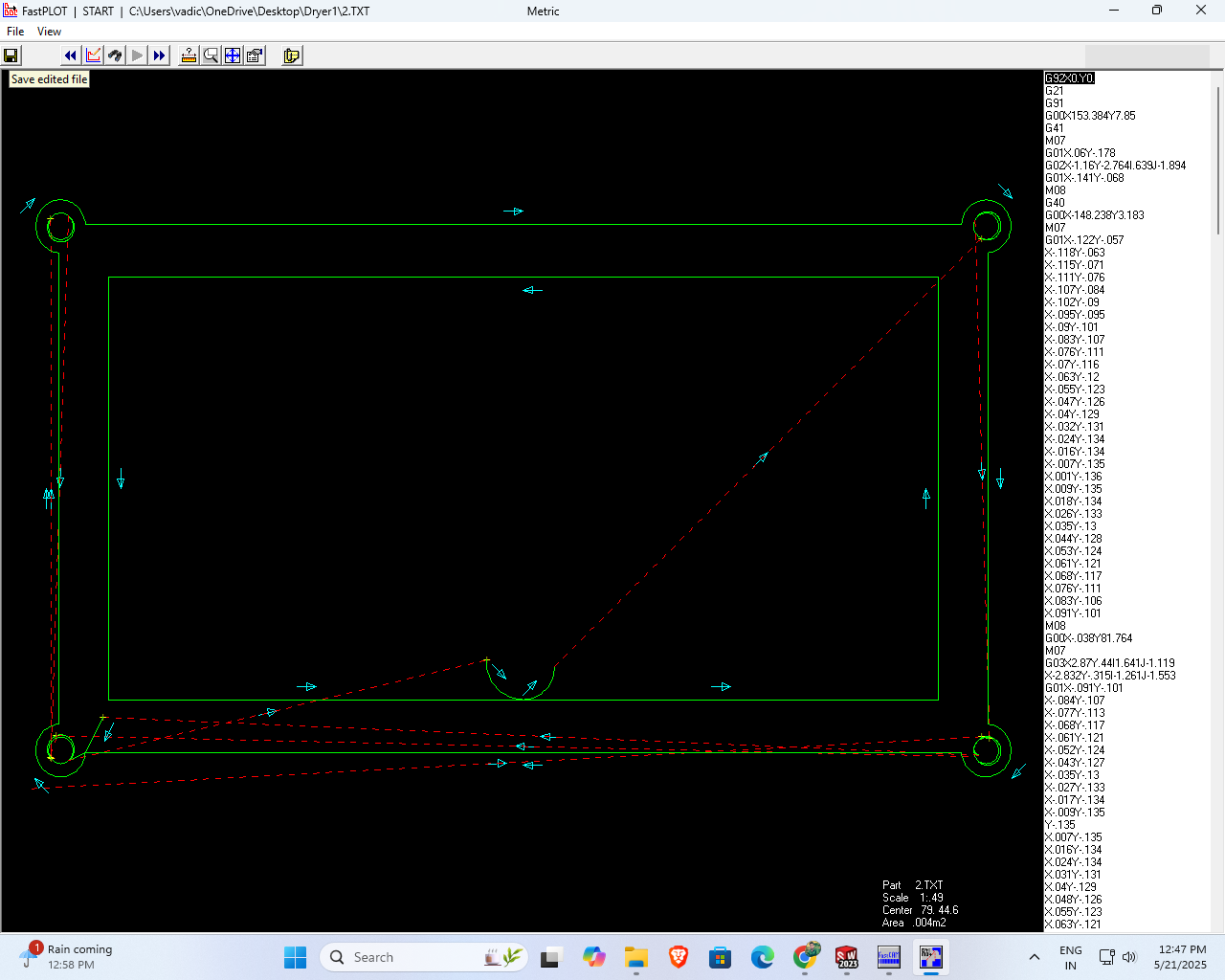
With the help of this software, I successfully generated the G-code for my design and saved it in a .TXT file format, which can be used for further machine operations.
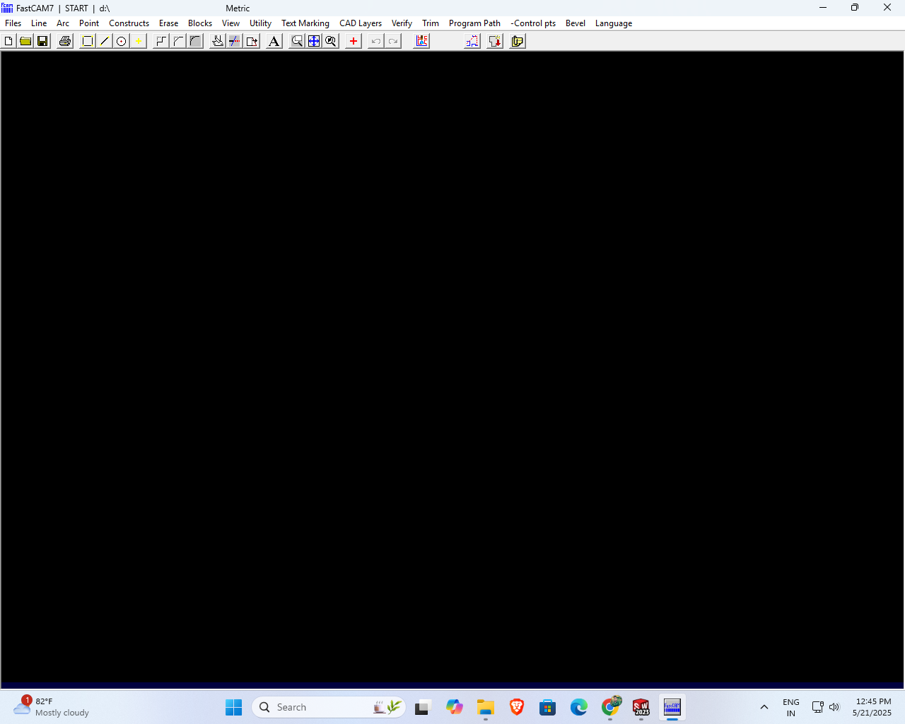
First, I opened the software, where I could see and access all the available functions and features.
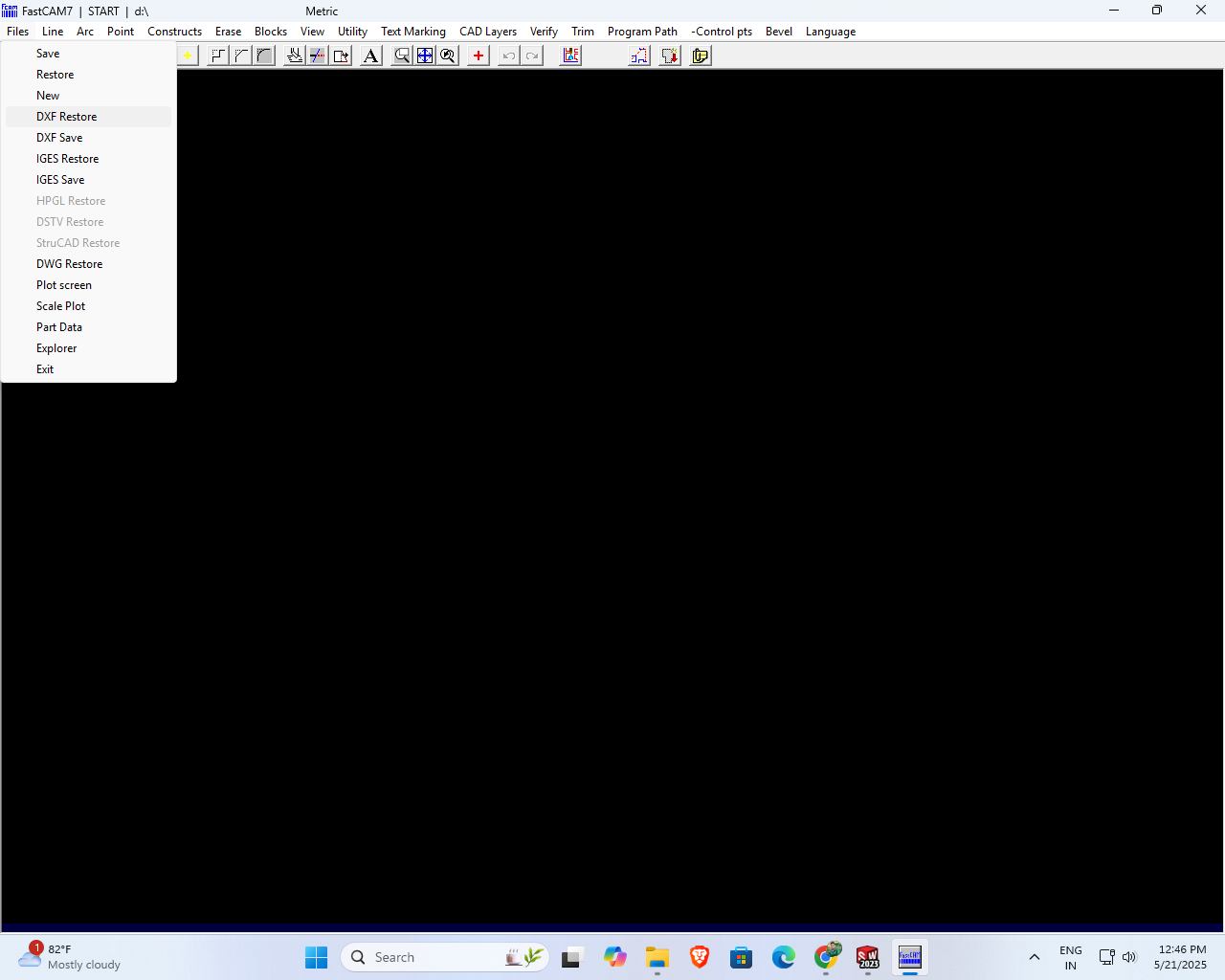
Then, I clicked on the file and selected the 'DXF Restore' option to proceed further
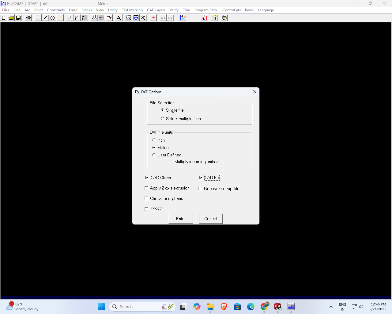
A small DFX options window appeared on the screen. In this window, I checked the options “CAD Clean” and “CAD Fix” to ensure the file was optimized for further processing. After selecting these options, I clicked the Enter button to proceed.
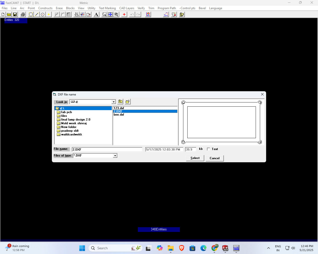
I searched my pendrive for files with the name "123" that support only the DWG and DXF file formats.
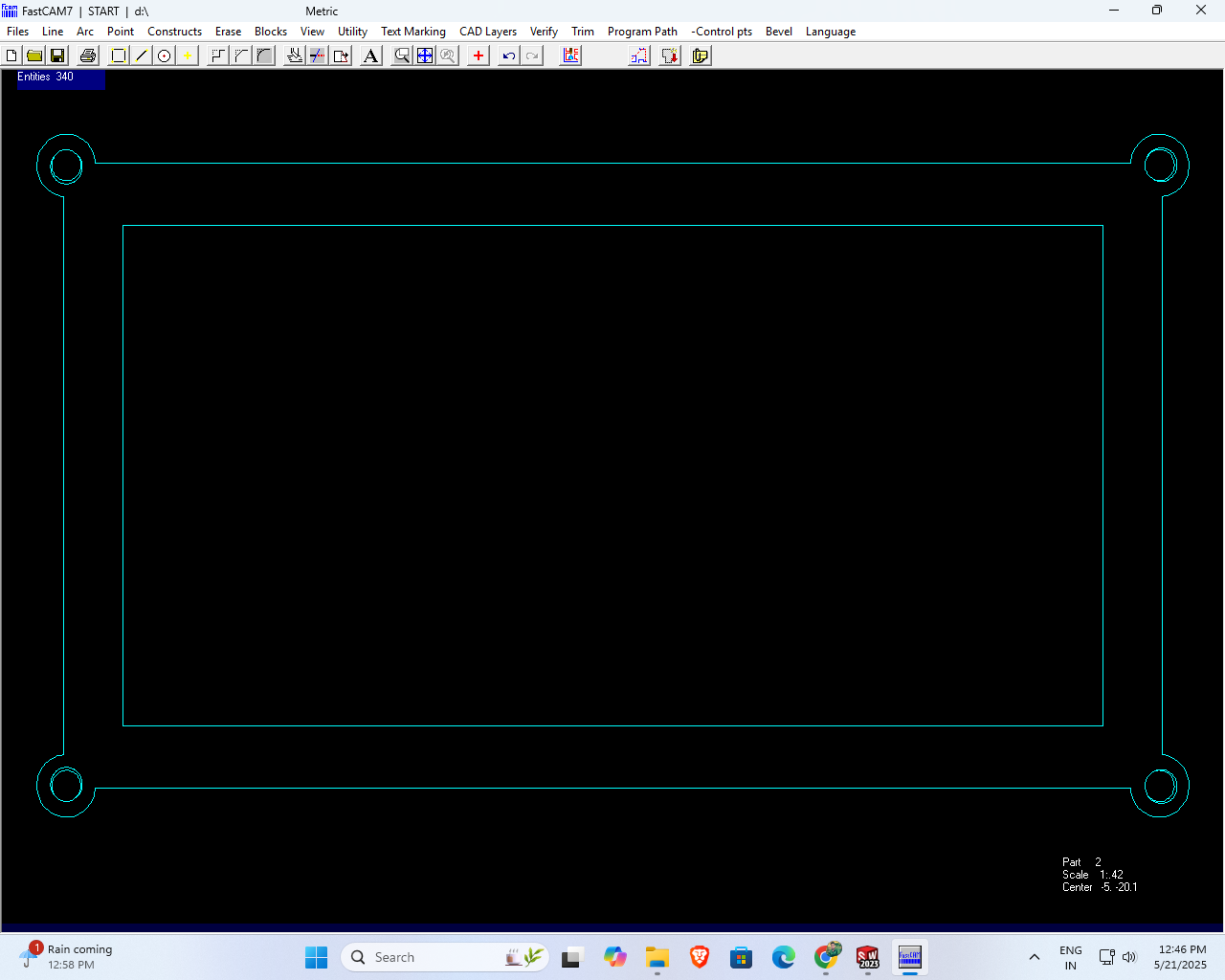
After selecting my file, the design appeared clearly on my screen.
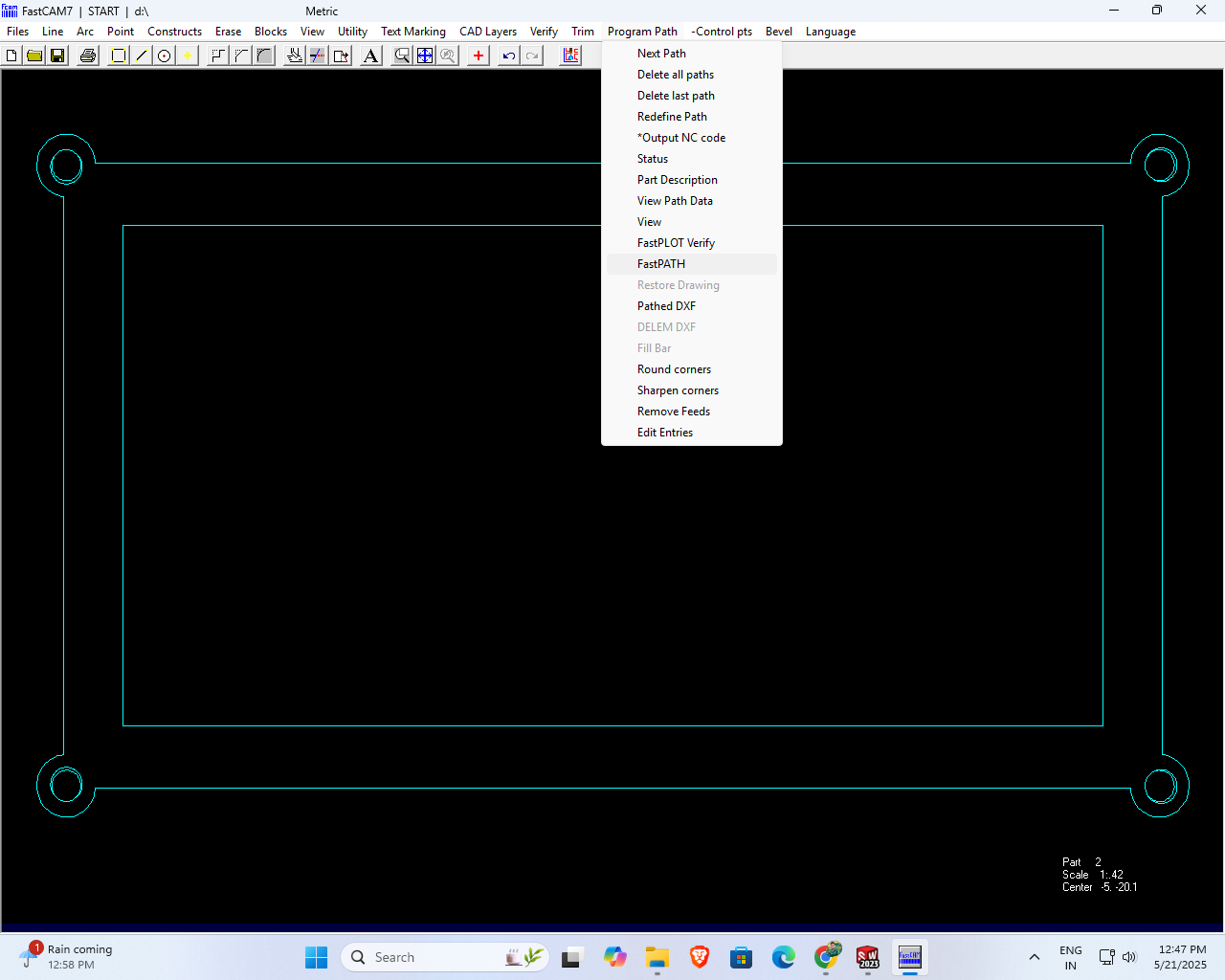
Next, I clicked on the Program file, and from the dropdown menu, I selected the Fast Path option.
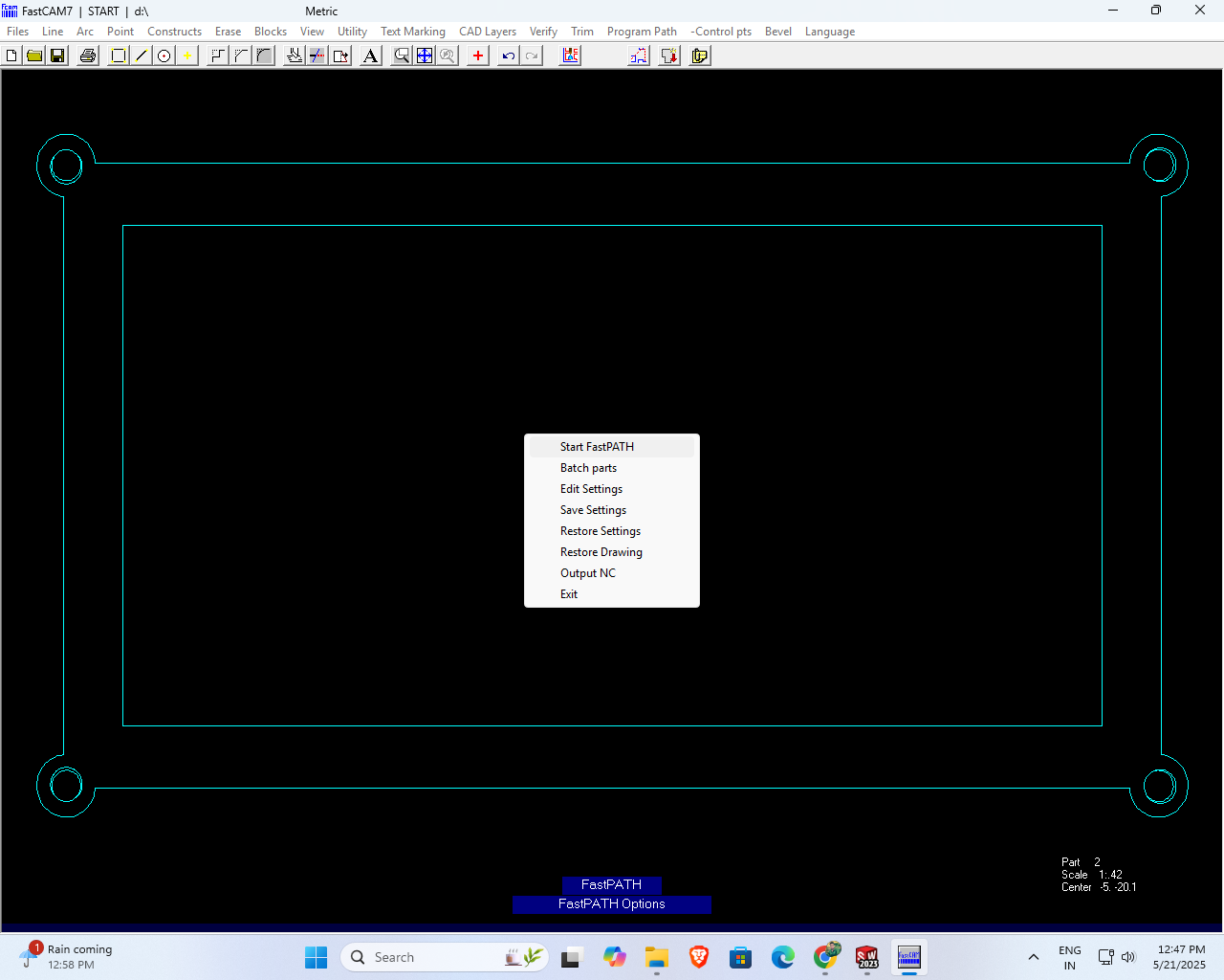
Then, I clicked on the 'Start Fast Path' option to begin quickly
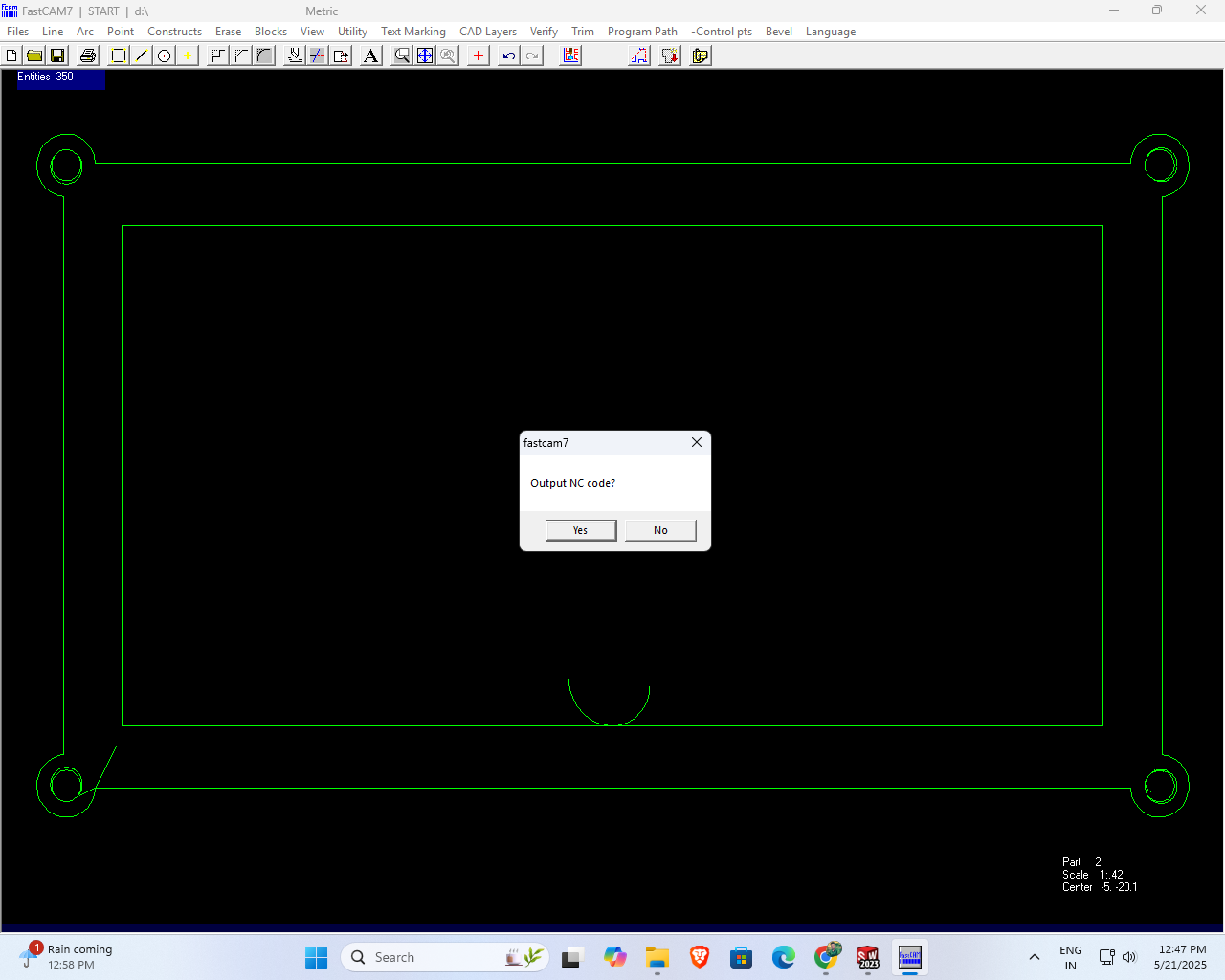
Then, the output is the NC code that is generated when the 'Yes' button is clicked
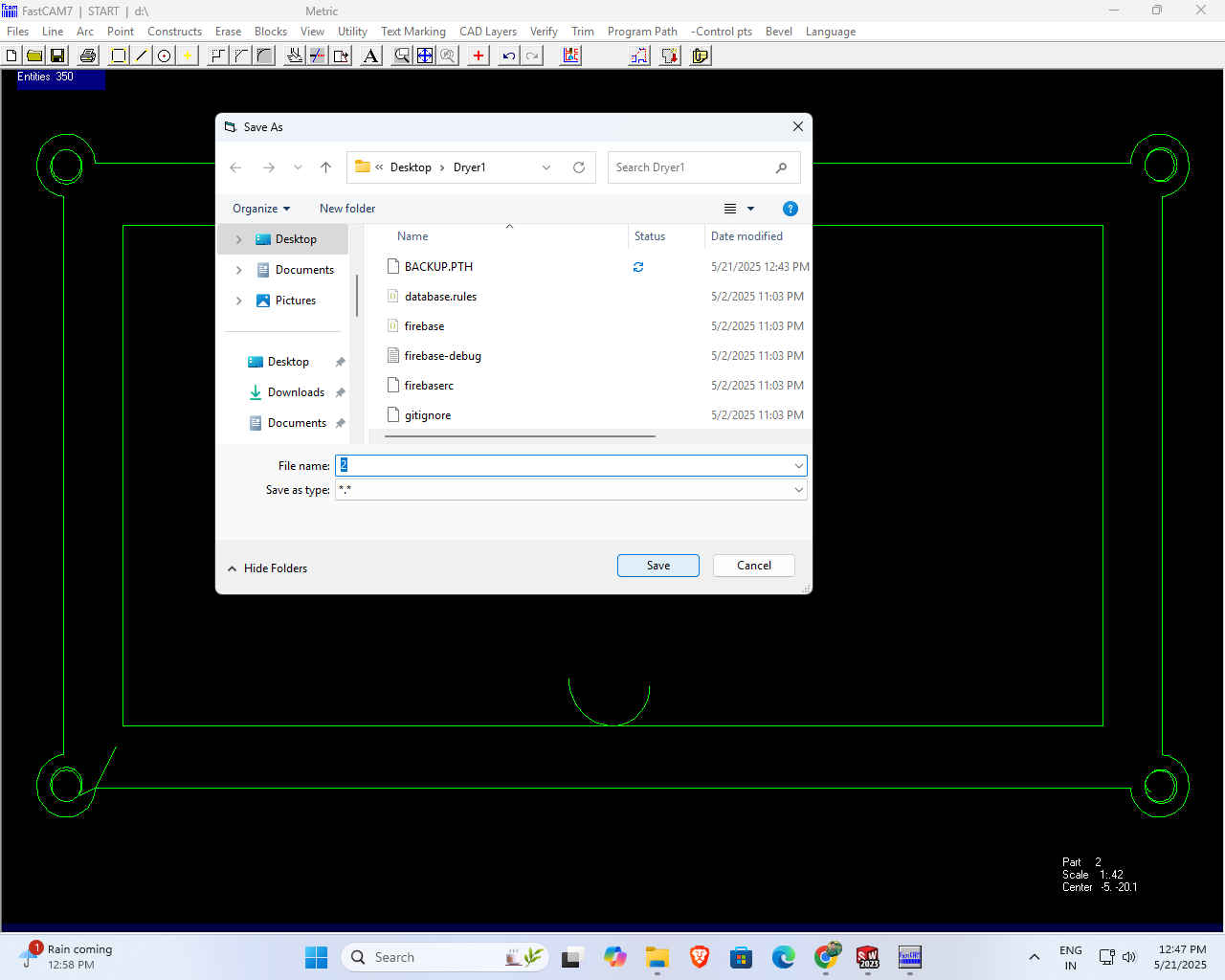
After completing my work, I saved the G-code file with the name "2" for future use.
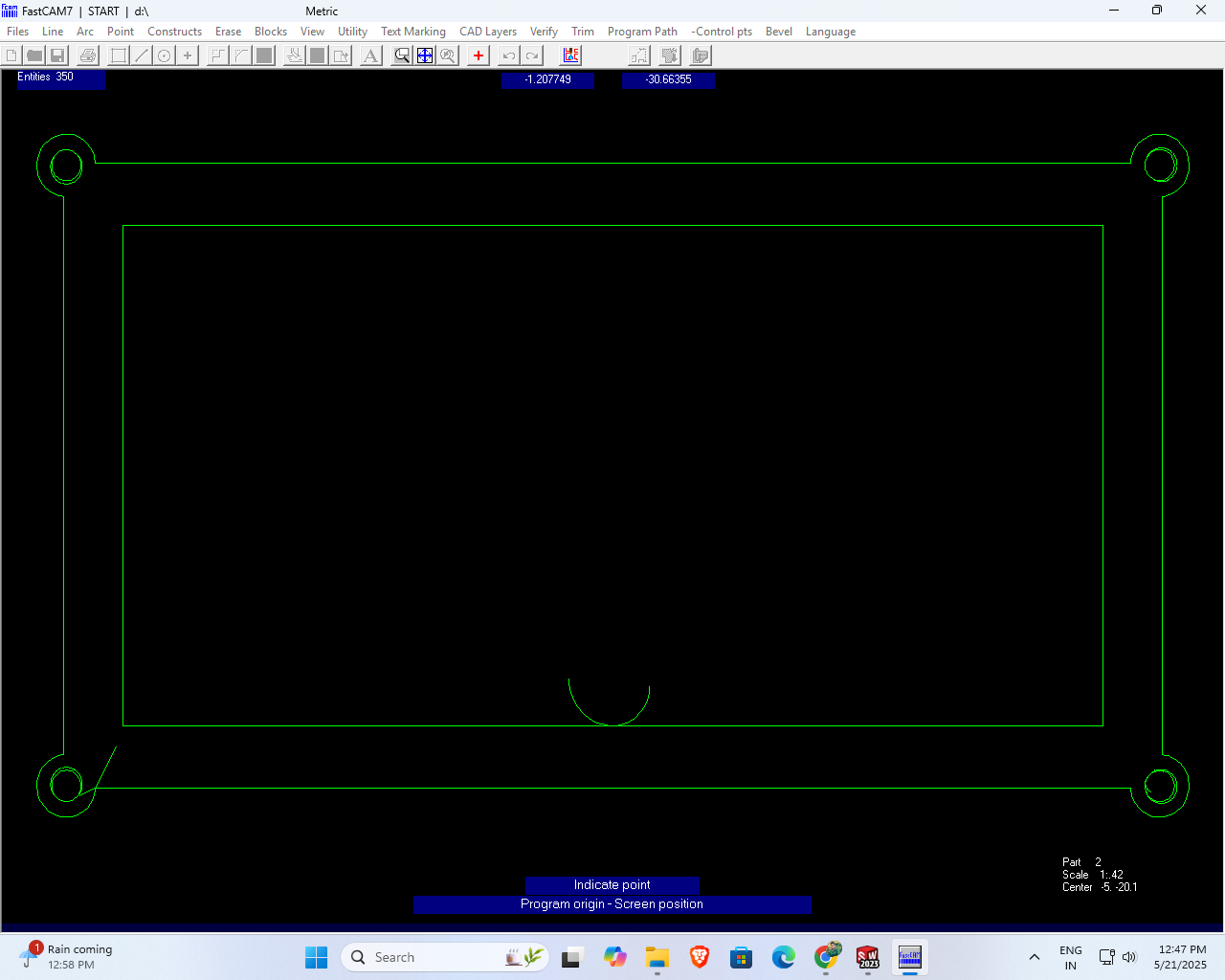
I clicked on the lower-left corner of the design interface where I needed to set the origin point.
After I double-clicked, the toolpath for my design was successfully generated.
The toolpath was successfully generated without any errors, ensuring accurate and efficient machining for my project.
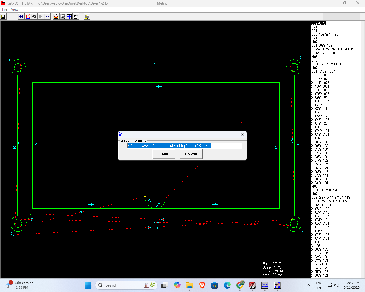
Next, I selected the 'Save Toolpath' option and saved the generated file with the name '2' for further processing and documentation.
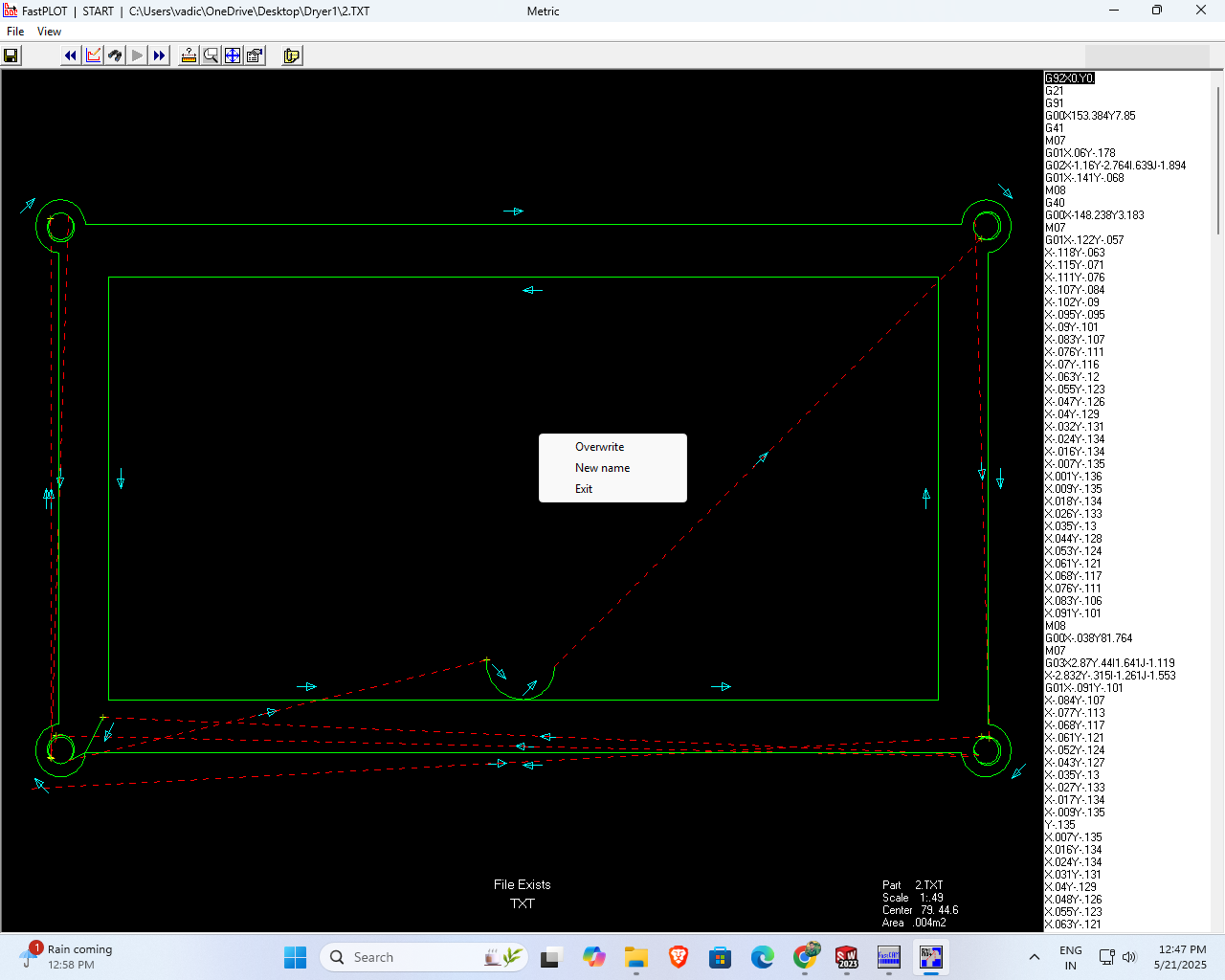
Finally, after completing all the necessary steps, I clicked on the 'Exit' button to safely close the program and end the session.
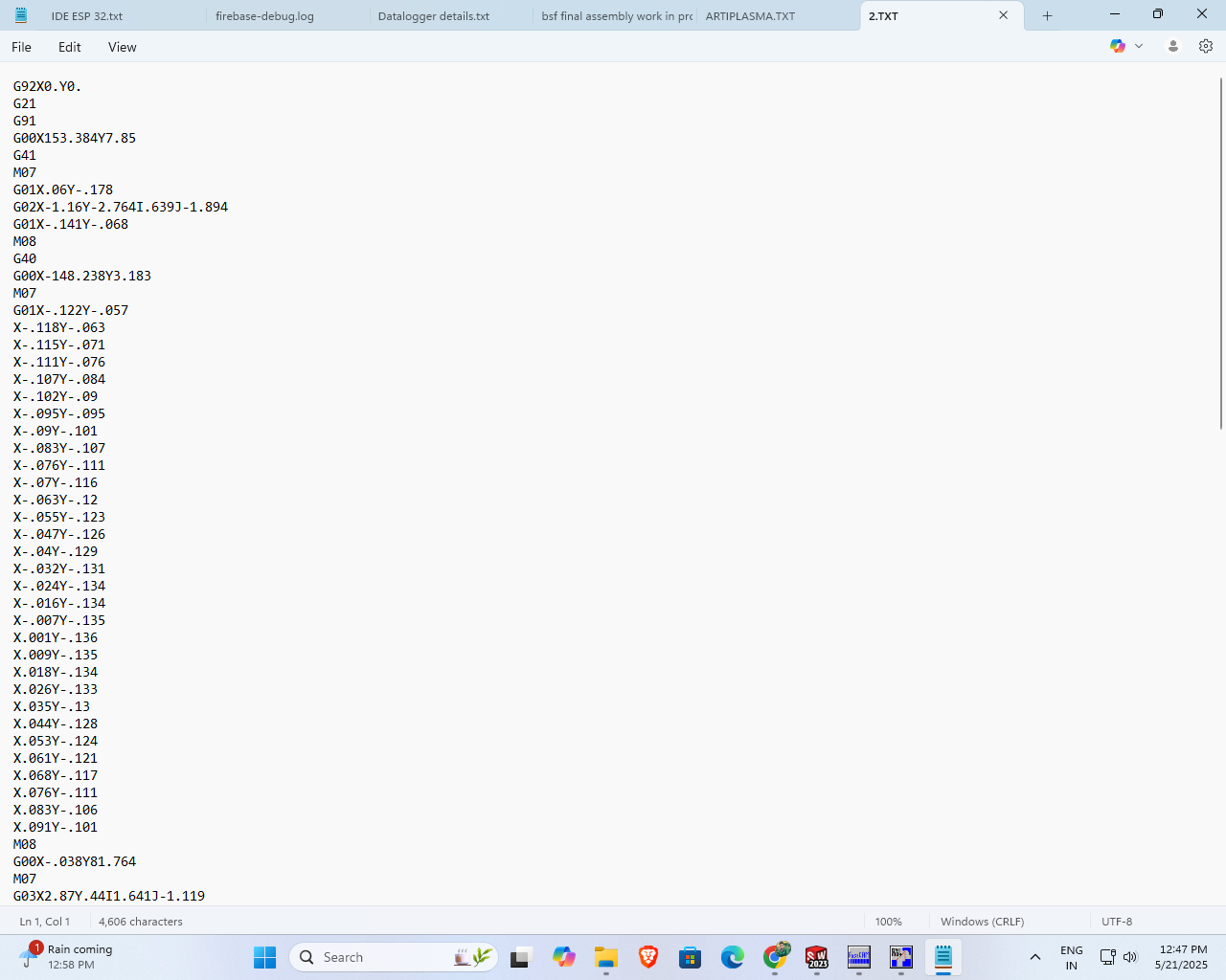
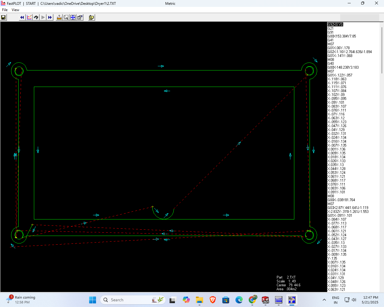
Finally, I opened the text file and reviewed the G-code that I had generated
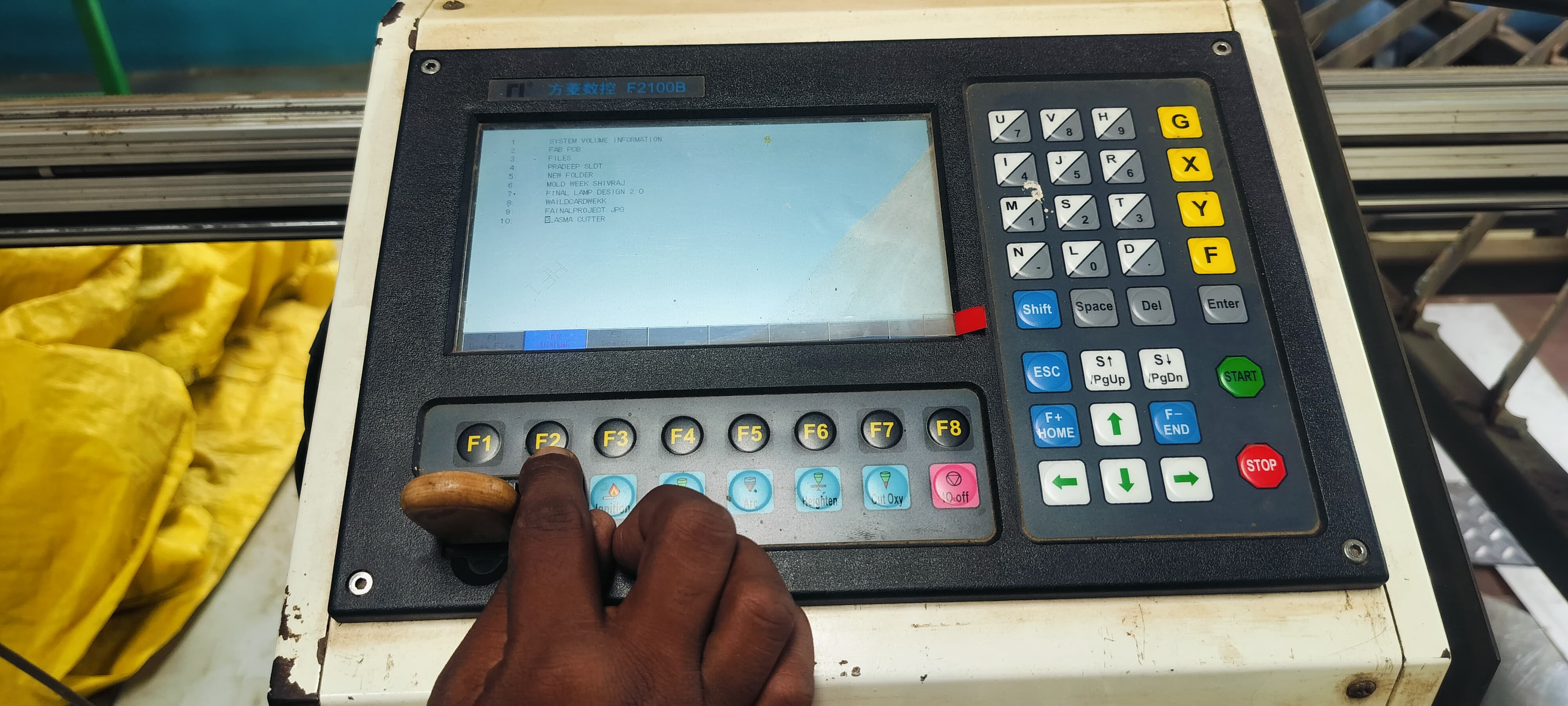
First, I inserted the USB drive into the machine and powered it on. Then, I searched for my design file by pressing the F2 key.
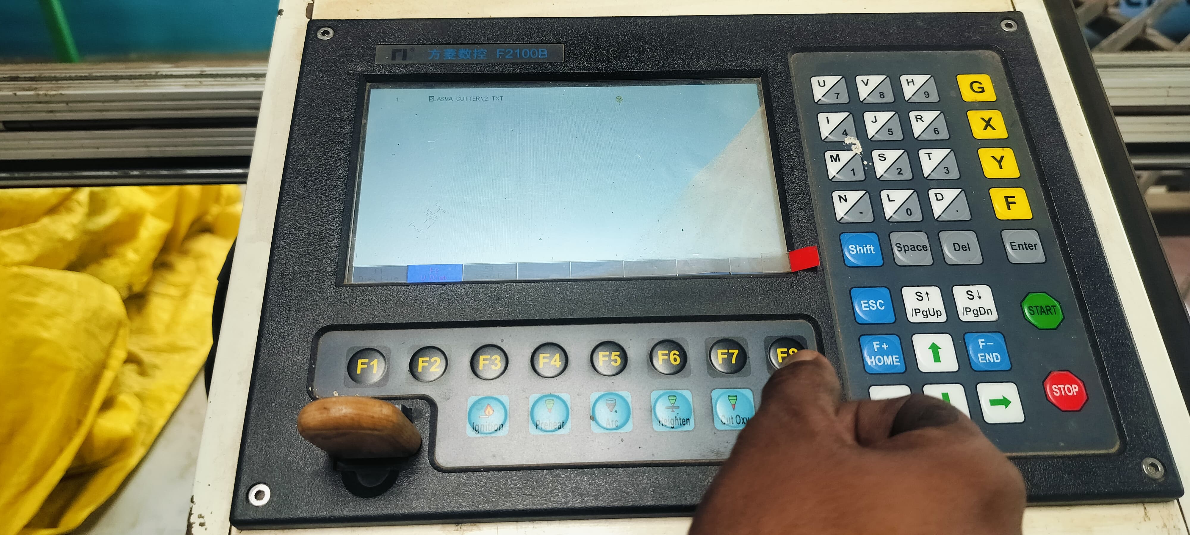
To select the desired file, I clicked on the F8 key.
After clicking F8 again, the screen displayed the G-code version of my design.
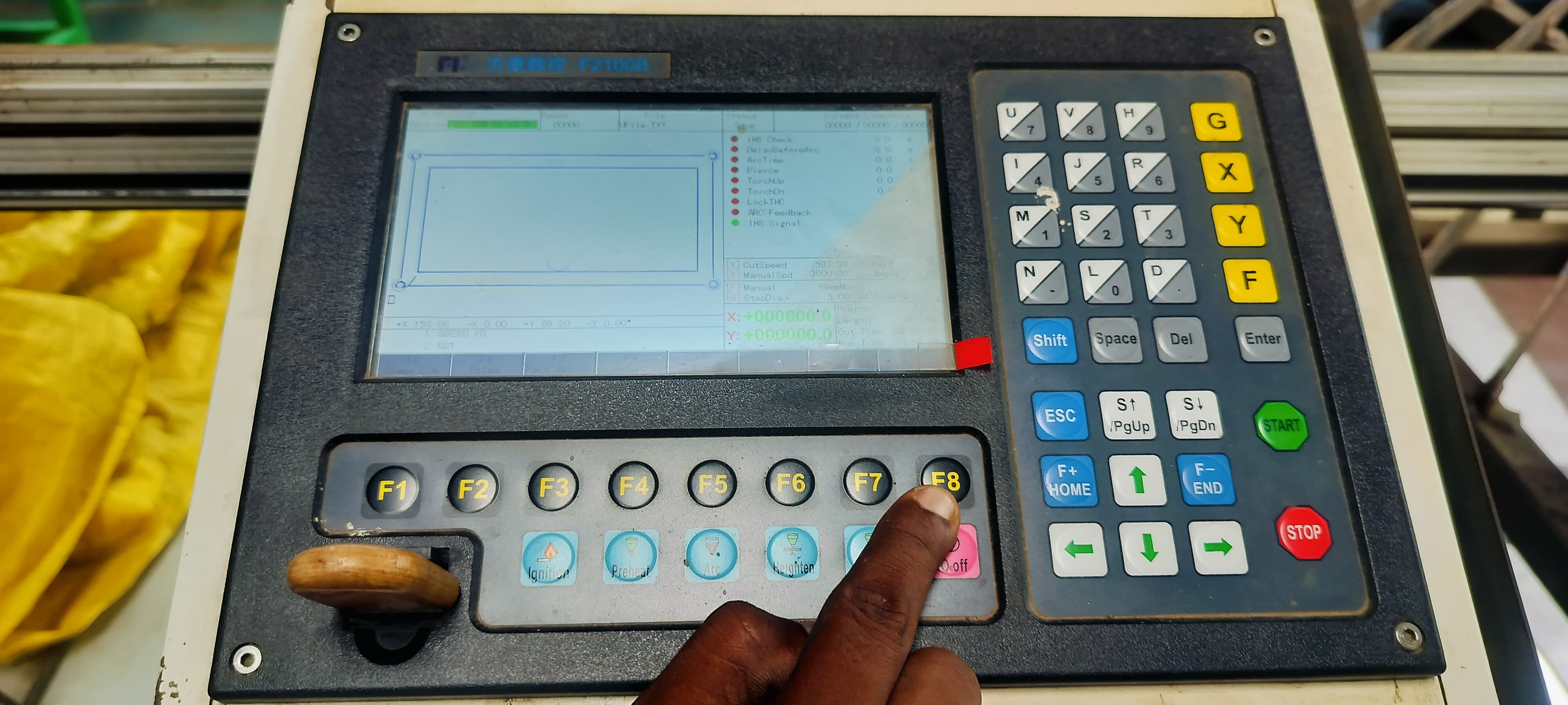
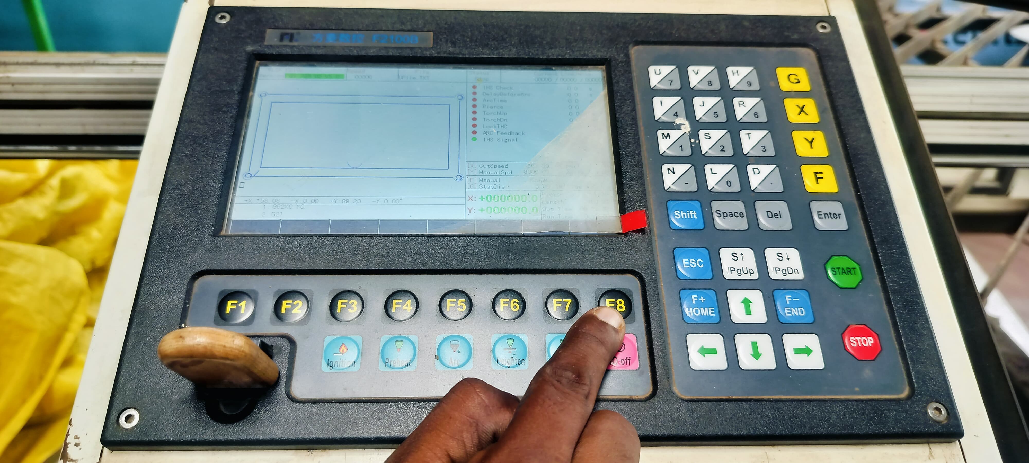
To proceed with the design preview, I clicked on the F8 key once more.
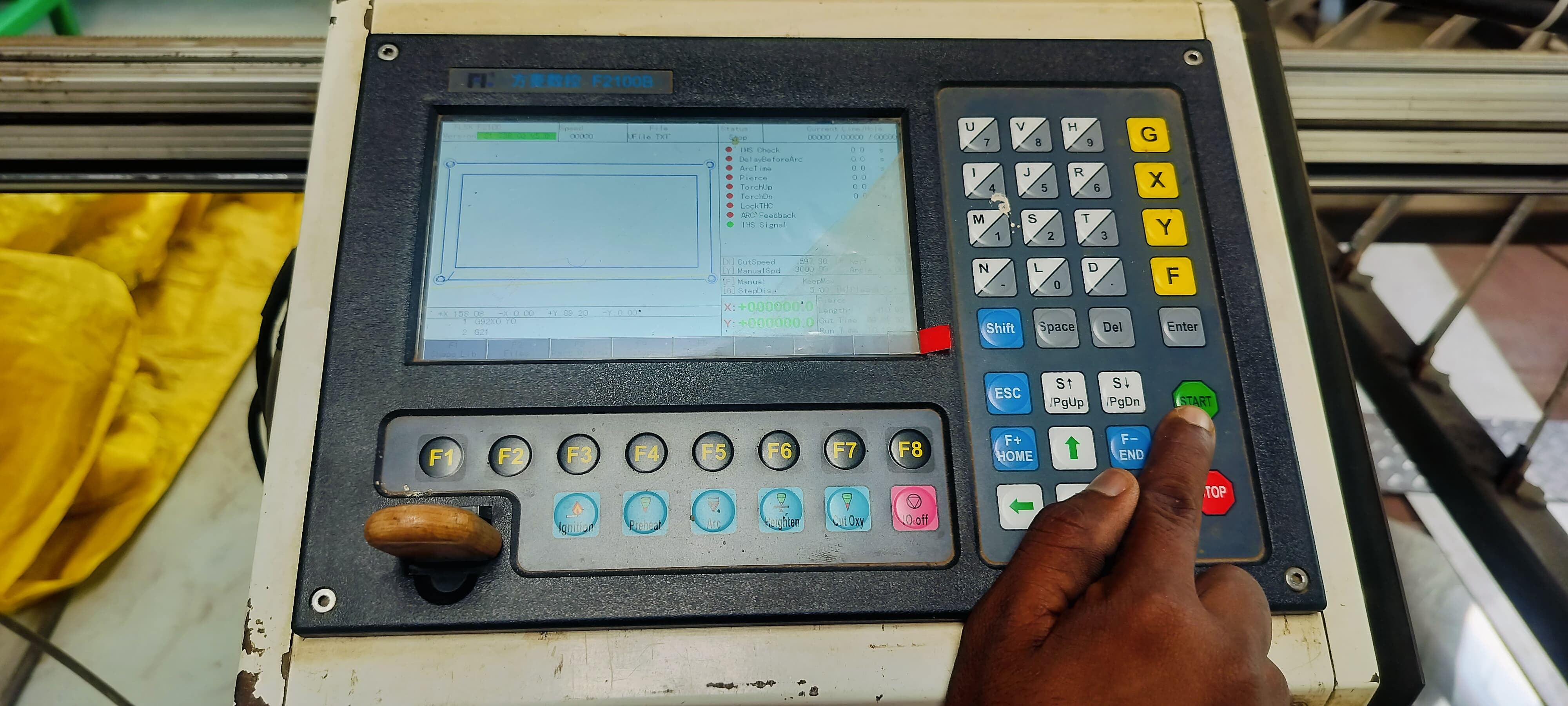
Before starting the cutting process, I properly placed the metal sheet on the plasma cutter and pressed the Start button.
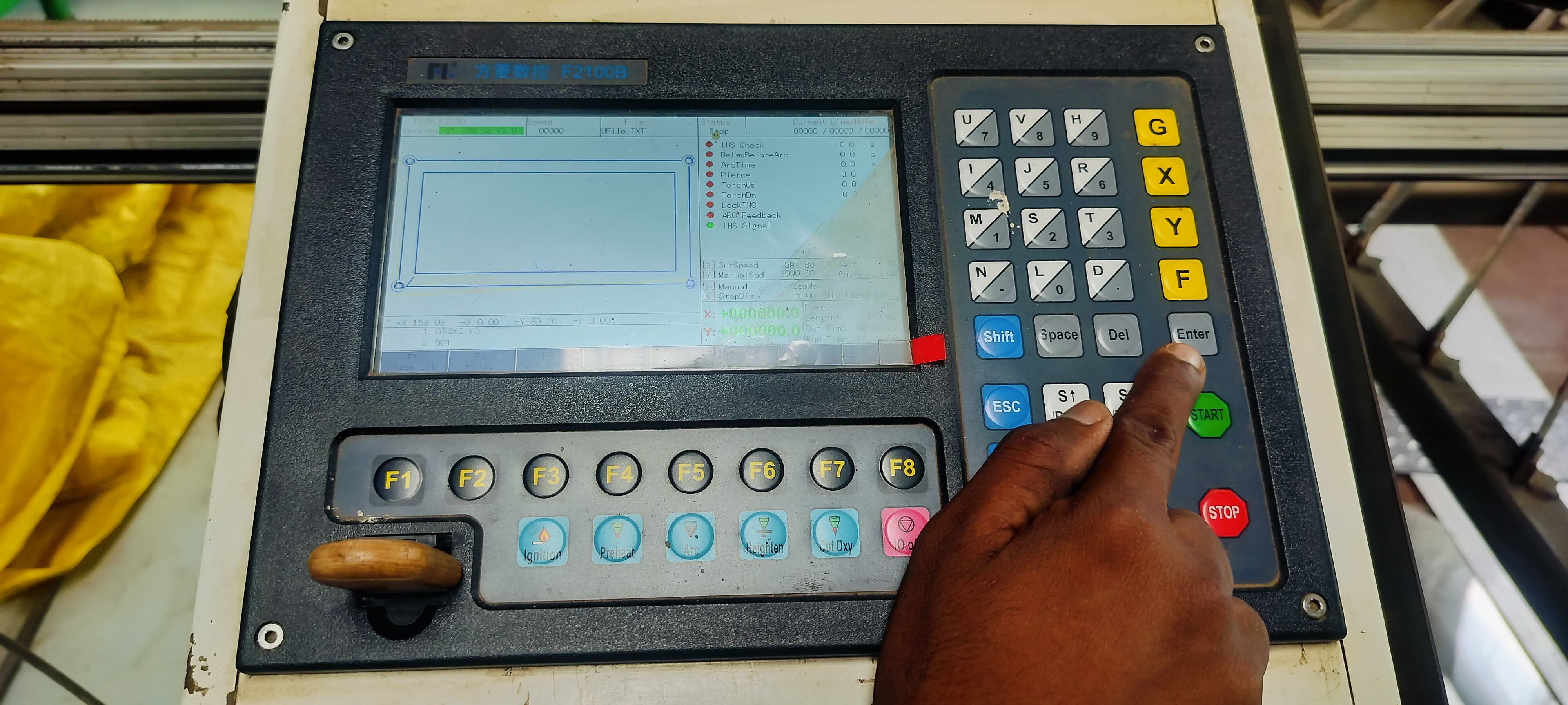
Then, I pressed the Enter key to initiate the cutting operation.
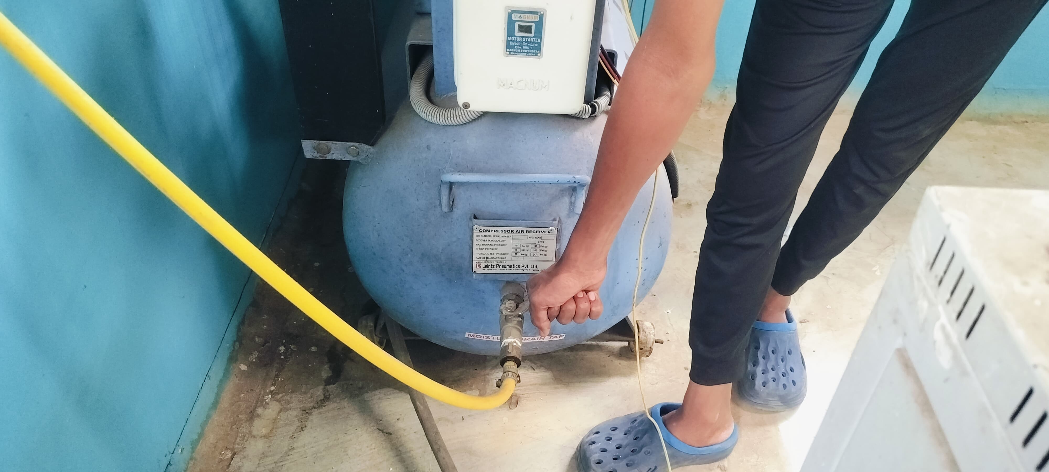
Finally, I turned on the compressor, which was connected to the plasma cutter, ensuring proper air pressure during cutting.
The plasma cutter began operating according to my design file instructions.
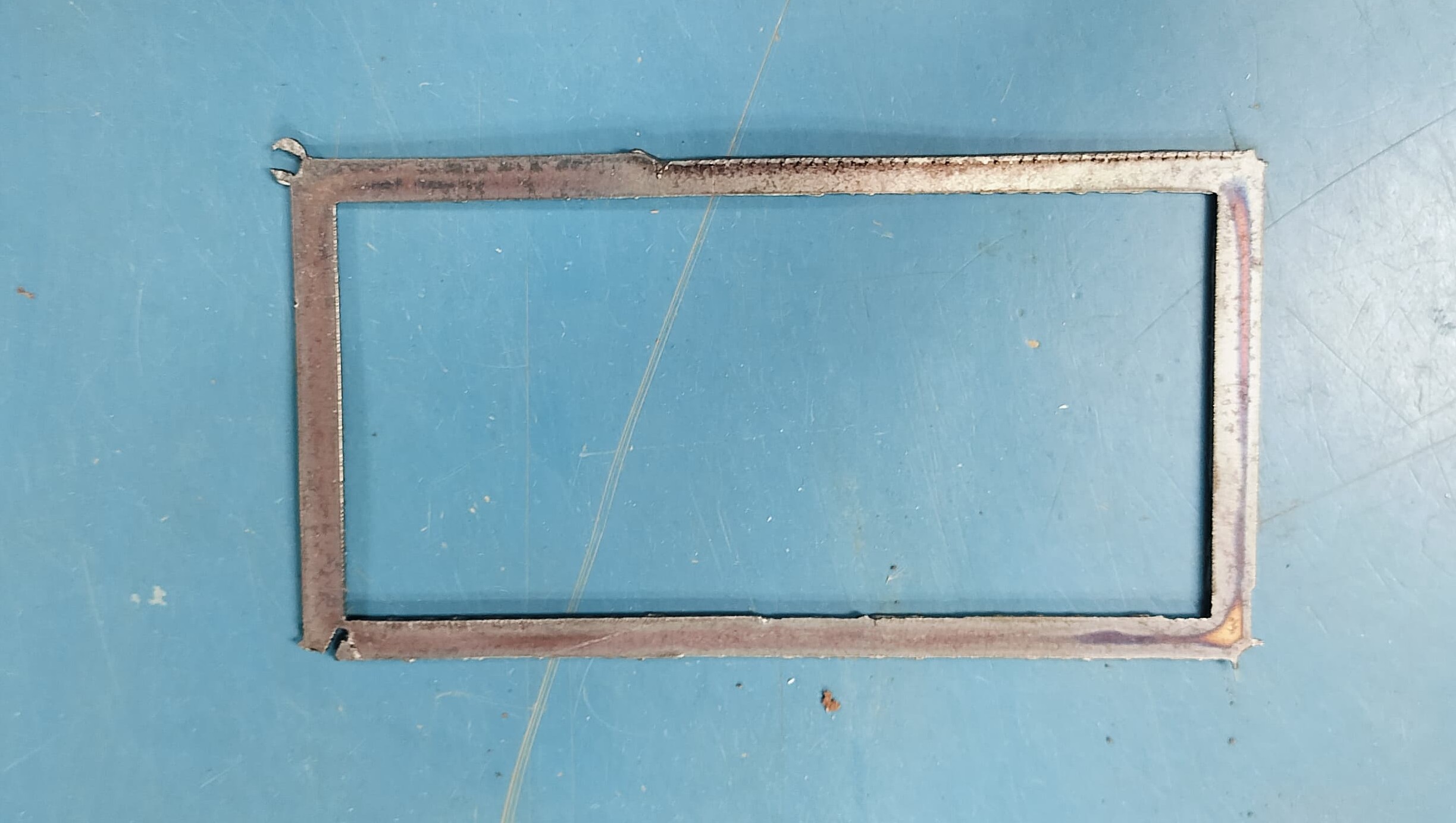
This is the final output after the plasma cutting process was completed.Due to the constraints caused by the curve in the design, I realized that a larger and more suitable design needed to be developed to match my original concept. The earlier version was not compatible with the plasma cutter, as it did not perform well during the cutting process. Taking this limitation into account, I created a new design that aligns with the technical requirements. I have followed the entire fabrication process step by step, which is documented in the section below.
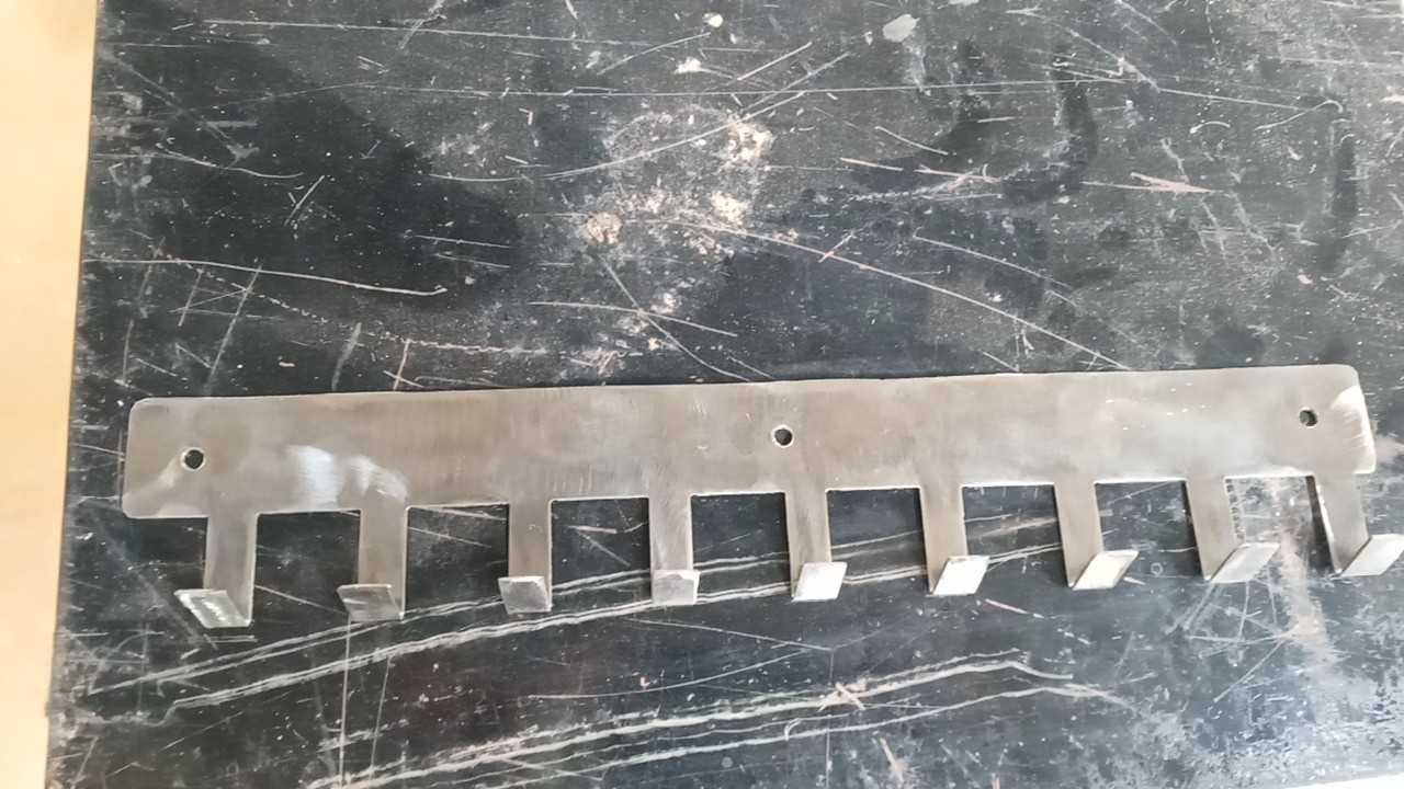
In my previous project, I successfully utilized a plasma cutter to shape the material according to a predefined pattern. After completing the cutting process, I proceeded with grinding and bending operations to refine the form. These combined efforts allowed me to achieve the final object precisely as intended, matching the original design specifications.