Week 8 Group Assignments -
- Group assignment:
-
Characterize the design rules for your in-house PCB production process: document feeds, speeds, plunge rate, depth of cut (traces and outline) and tooling.
-
Document the workflow for sending a PCB to a boardhouse
-
Document your work to the group work page and reflect on your individual page what you learned
Characterize Design Rules
The Super Fab Lab uses the Roland Monofab SRM-20 machines for PCB manufacturing and that is what was tested in this assignment.
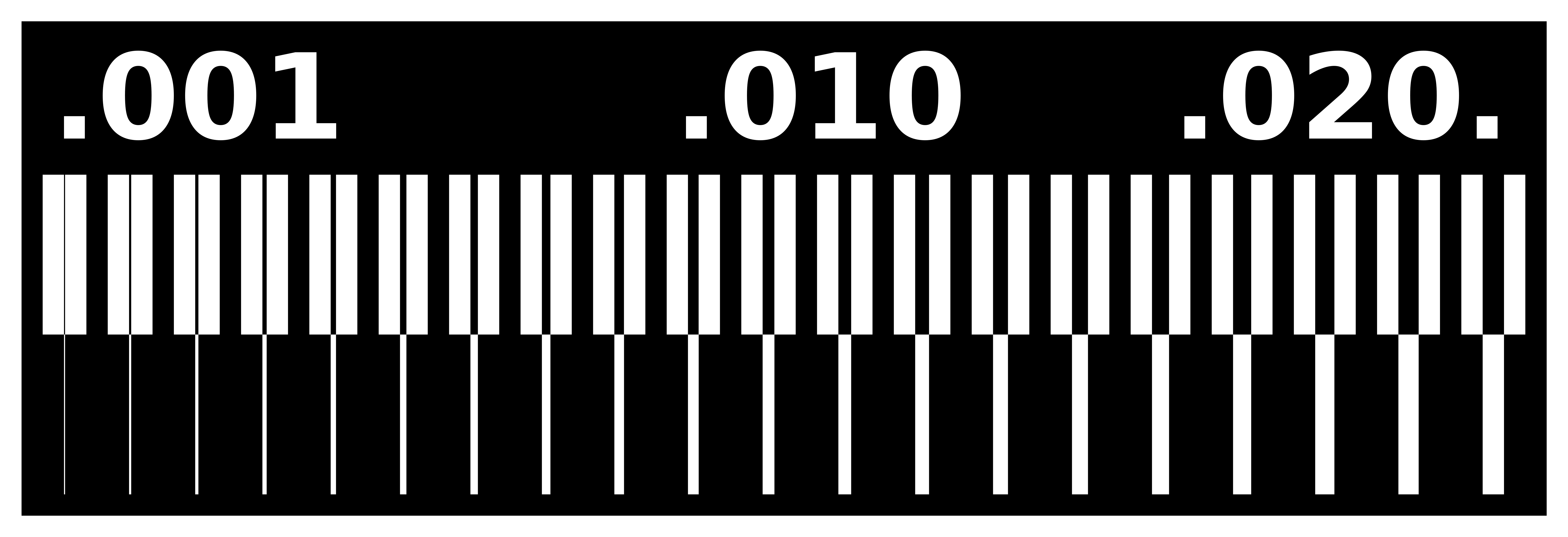
Trace Width Testing
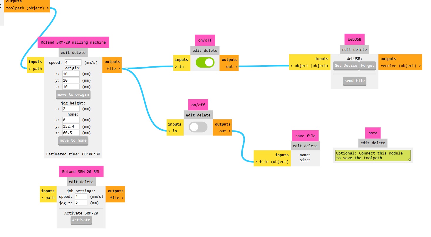
Mods Toolpath Setup
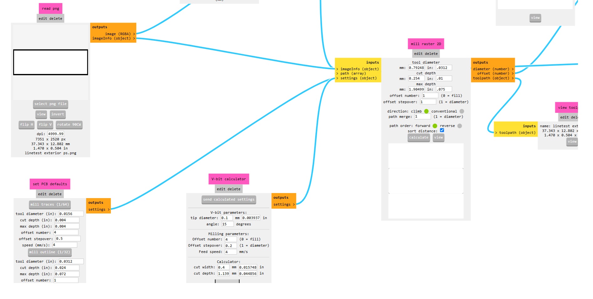
For the trace width testing we used the MIT Mods program to generate the toolpath. We started by opening up a new “Mill 2D PCB” instance under the Roland SRM-20 menu in the software. Then we imported the PNG in the “Read PNG” block. The software loade the data which was transmuted to the blocks downstream. Then leaving all of the default settings, we clicked the calculate button on the “mill raster 2D” block. This calculated the toolpath.
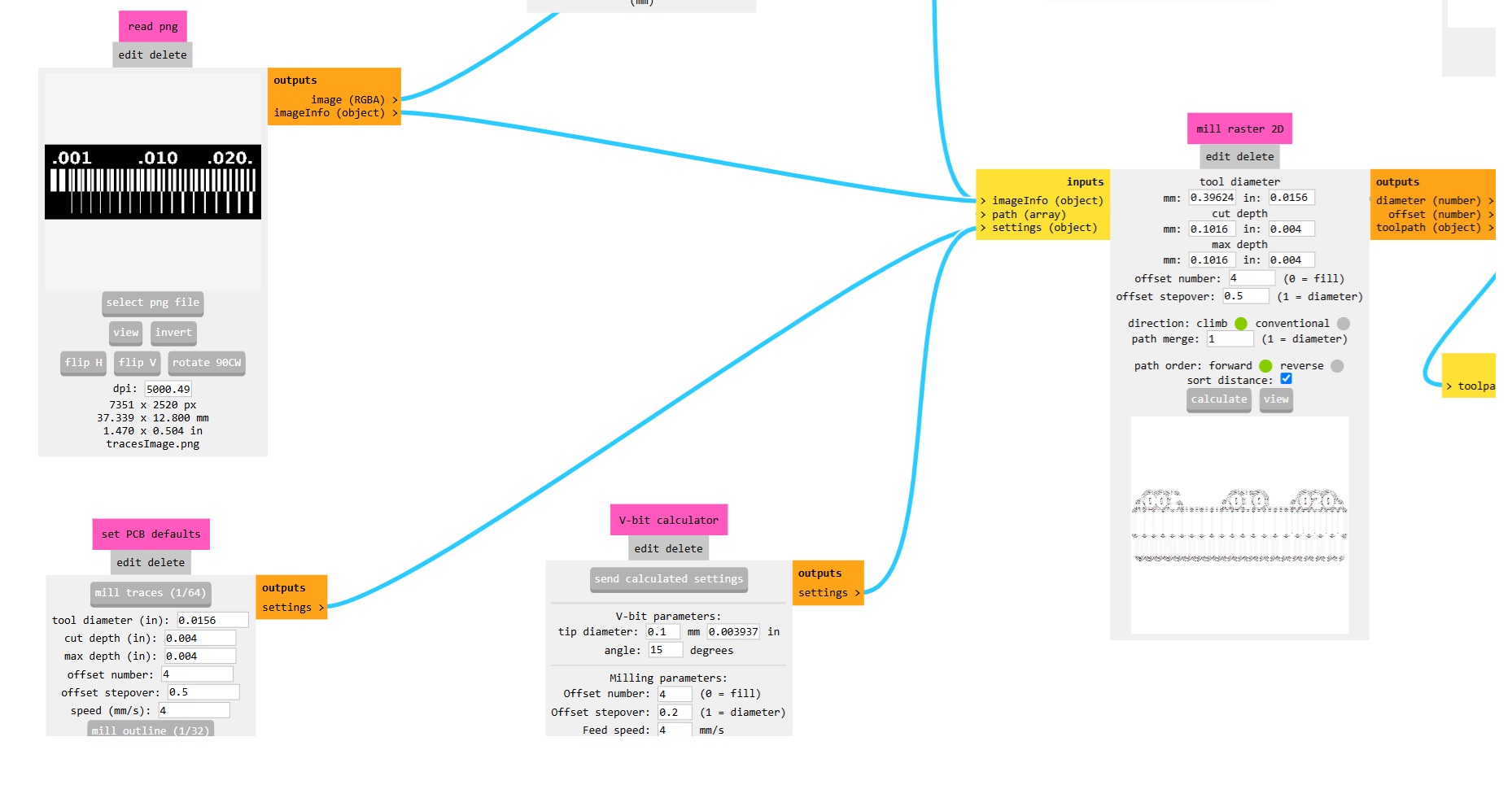
Note the default settings for a 1/64” endmill used are
Cut Depth (in.): .004 Speed (mm/s): 4
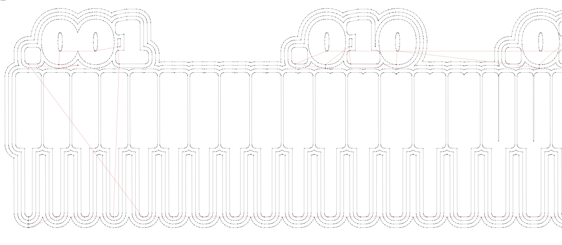
For the toolpath we used an offset of 4 and stepover of .5 diameter.
Then we could click on the view button in the same block so we could see the traces. It showed the 4 distinct toolpaths surrounding the geometry of the board.
The toolpath looked correct, so we switched the toggle switch further downstream in the workflow to allow the file to be saved. When we toggled that on, it exported an .rml file to the downloads folder on the computer.
Machining
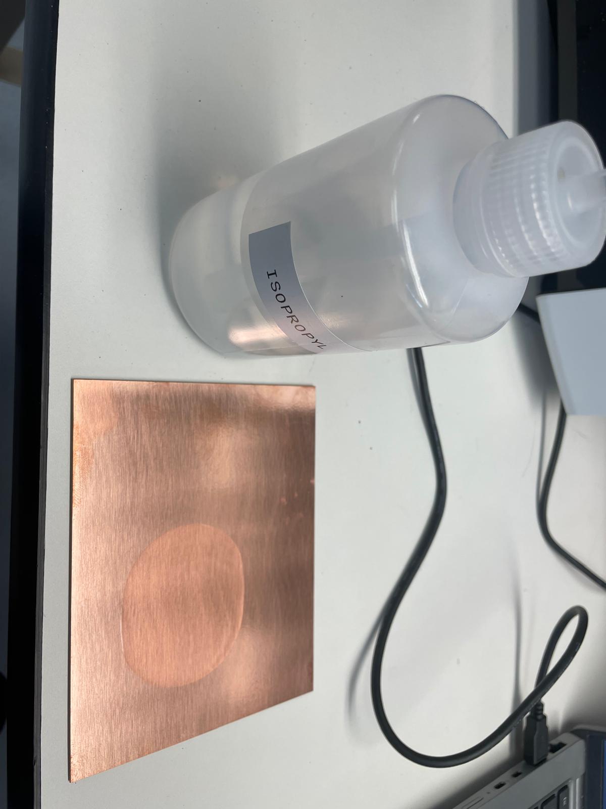
Then we were able to do the machining of the PCB. We went to the machine and started by vacuuming it out from the previous job. Then we wiped down the spoil board to free it from debris. We chose a new FR1 double sided PCB board and cleaned it with some alcohol and a paper towel.
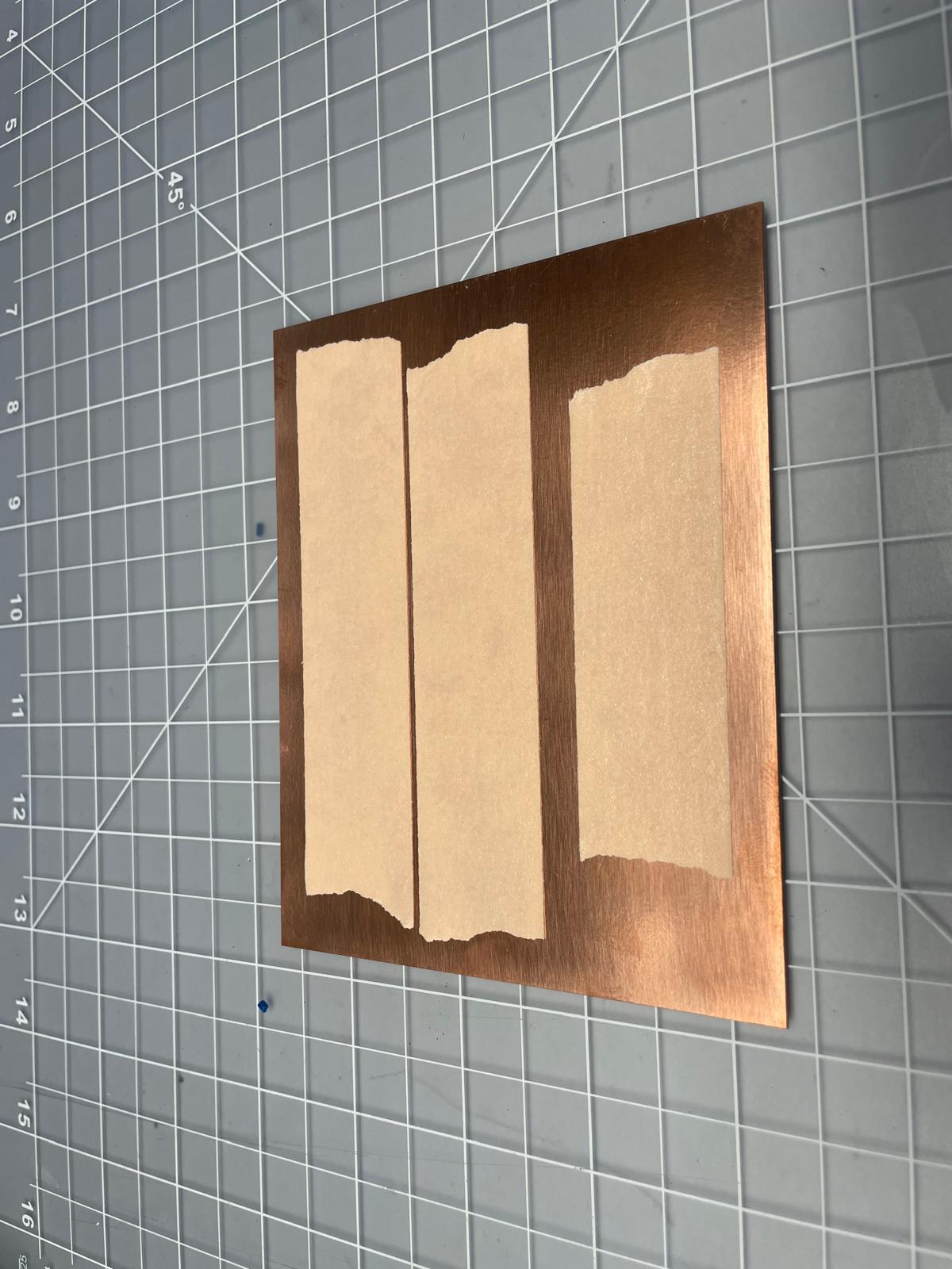
Then we put a few pieces of double sided tape down onto the board.
Then we placed the PCB in the mill, adhering it to the spoil board.
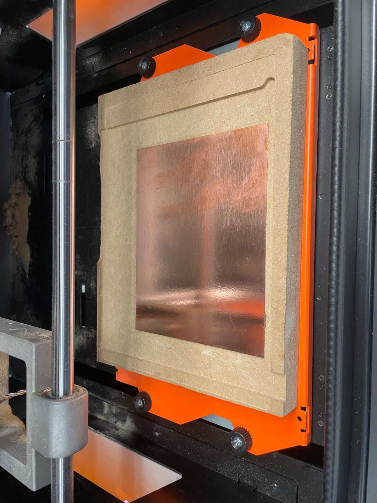
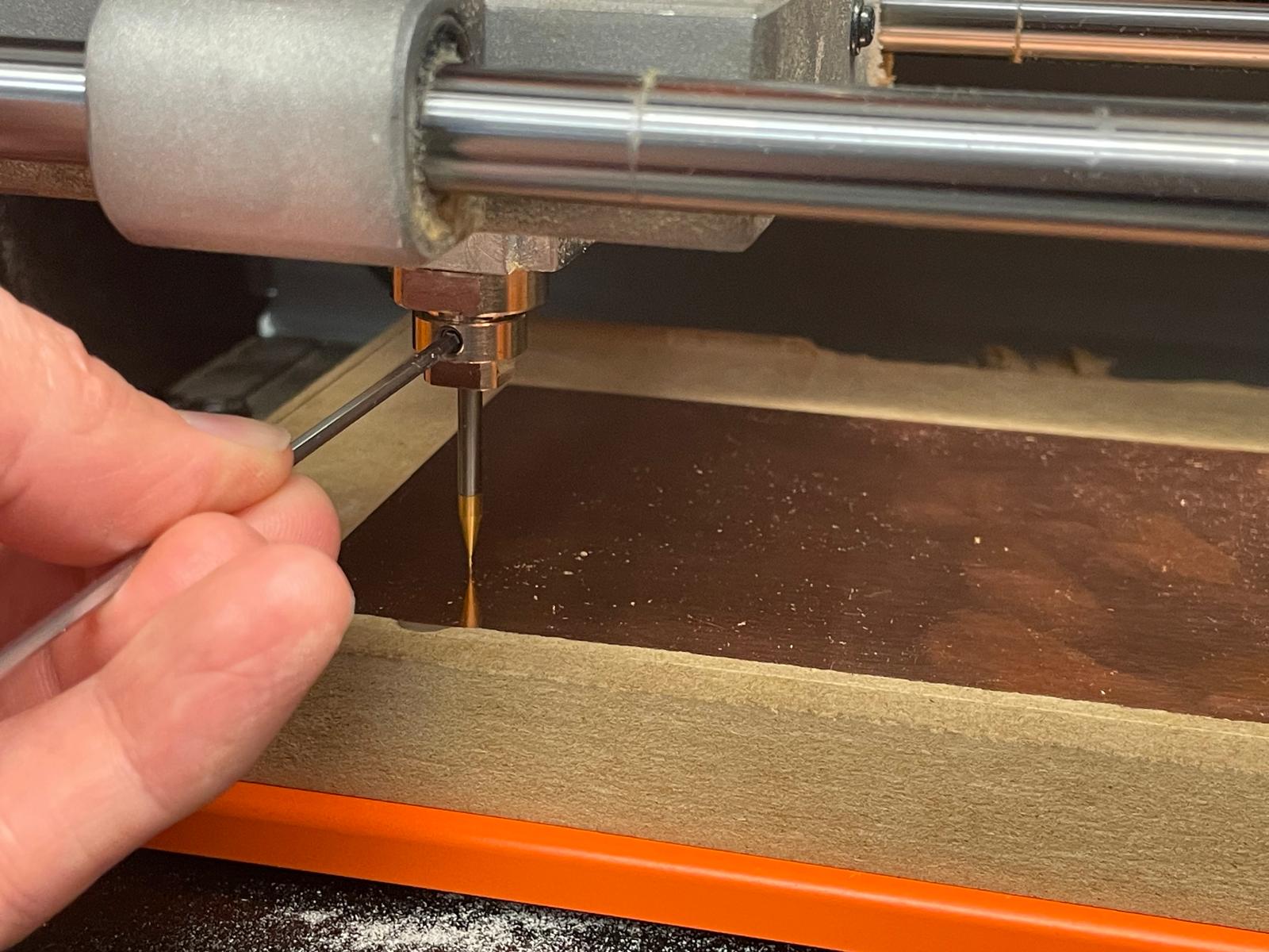
Then it was time to zero our axes and run the job. We turned on the SRM-20, inserted the USB into the computer, and opened up the VPanel software. This is the software used to move the machine and run jobs. We installed the 1/64” bit into the spindle and had the shank of the mill pushed up far into the collet. Then we lowered it to within a 1/4” of the copper and moved it to the front left corner of the piece. Once there, we clicked the zero X/Y button in the software. Then we moved the axes about 10mm in both X and Y so the bit was inset from the edge of the piece. Then we loosened the setscrew on the collet and lowered the bit until it contacted the surface of the copper. Then we tightened the setscrew while lightly holding the mill down onto the copper.
Then it was time to do the cutting. We went back into the Roland software and loaded the file that was exported and sent to the ‘Downloads’ folder. Then we clicked Run and kept the mouse hovered over the pause button while the mill started spinning and moving into place. Once the tool made it to the path start and started running the program, we realized that the tip of the tool was 9.9mm above the surface of the part and cutting in the air. We cancelled the job and then went back and reviewed the Mods setup and realized that there was a 10mm offset on all axes in the “Roland SRM20 Milling Machine” block. We changed these values all to zero and the new file automatically generated and saved to the Downloads folder. We then imported the updated file and ran it in the Roland software. This time the bit went down .01mm (.004”in) and ran the toolpaths properly.
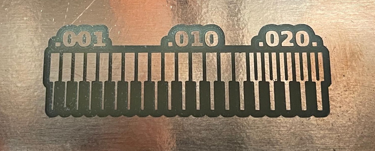
Then we wanted to test the thru cut paramaters. We made a black and white .png file with a border around the traces and numbers. We made a new Mods program and imported the new .png file. Then we selected the 1/32” endmill. In the ‘Mill Raster 2D’ block we changed the cut depth to .01in and the Max depth to .075in to do 8 shallow passes to get through the board. We changed the offset to 1 to make just a single path. Then we saved this file from Mods to the downloads folder.

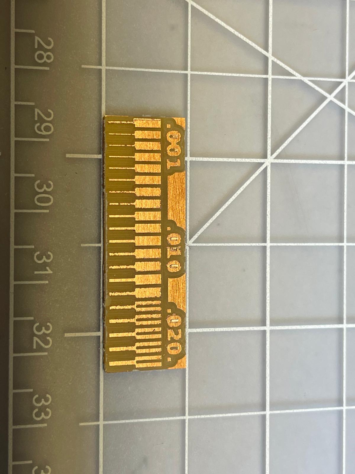
The we made a new part. We moved our X/Y zero point above the first cut in the Roland software. Then we ran the file with the traces to make a new trace pattern. Then we loaded the cut file and ran it. In just a few minutes the path was done and we gently lifted the finished board from the doublesided tape.
Sending to Board House for Quote
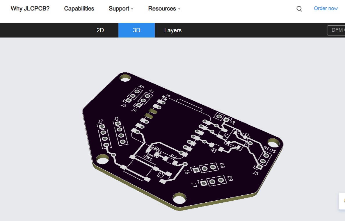
We started this process by signing up for an account on JLC PCB which wsa straightforward. Then we clicked the “Order Now” button which served a screen with a number of PCB options and a button to upload a Gerber file.
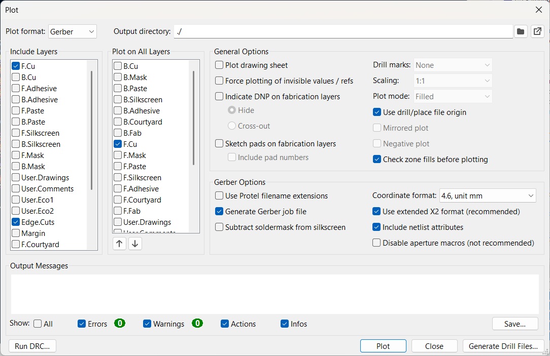
For the ordering test we used the PCB that Jeremy developed in Week 6. We opened the file in KiCad and went into the board file. The we selected File>Fabrication Outputs> Gerbers. This gave us a new menu with settings to output the design with different options. We selected the front and rear copper layers, the front and rear silkscreen, and the edge cut layers. Then we created a new folder for the output files and set the output location to the new folder. Then we selected the ‘Generate Drill Files’ to create the holes. Then we clicked ‘Plot’ to create the remaining files.
Since JLC only takes zip files, we went to the folder where the output files were created, right clicked it and created a zip file of the full file package. Then we went back to the JLC website and dragged the zip file into the upload window to send the files. In less than a minute the website indicated a successful upload of the files and gave us a rendering of the board from both sides.
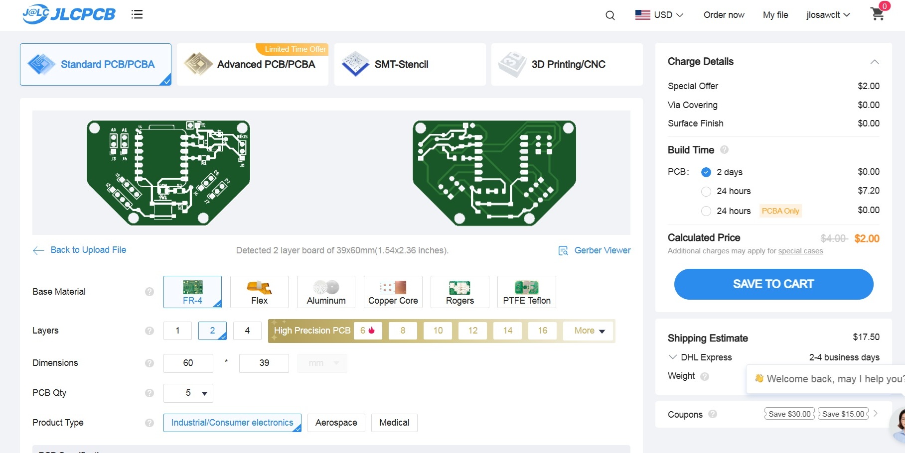
We then reviewed the rest of the ordering options. We noted different weight copper options, board thickness, color options, and tenting of the via holes. We changed the color to purple and selected untented vias and left the rest of the options the same as the default. With these options the total cost was $2 for 5 boards with $17.50 shipping estimate with 3 day build time.