Assignments
Group Assignment
- Try an input device's analog levels and digital signals
Individual Assignment
- Measure something: add a sensor to a microcontroller board
GROUP ASSIGNMENT
More specific detailed from the worked done with Ernesto Castro in Fab Lab Universidad de Lima here
d i g i t a l S I G N A L S and A N A L O G l e v e l s

We read digital signals and analog levels with the example boards in the lab and tried several inputs with an oscillometer connected to the respective board with some BNC connectors cables.
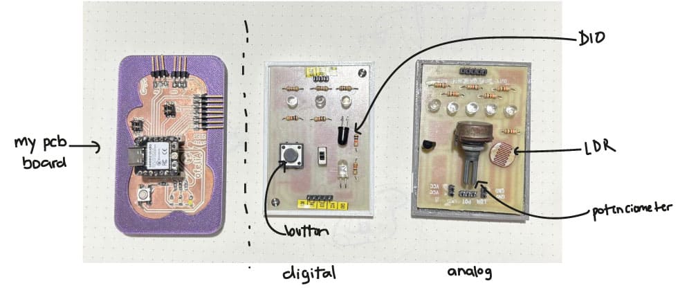
Lab boards with some components we tested
Our Instructor left us some assignments to read
- DIGITAL: DIO sensor ☑
- DIGITAL: Button ☑
- ANALOG: Potenciometer ☑
- ANALOG: Light intensity ☑
1. d i g i t a l: D I O
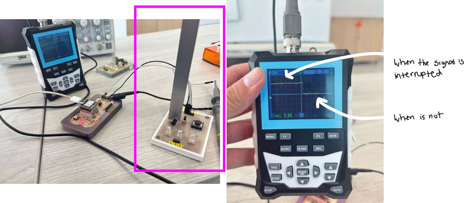
d i o process
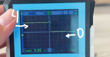 I tried the Digital Input/Output sensor by interrupting the signal with a simple ruler. It read in the oscillometer very differentiated how the digital signal changed. As each quadrant is valued 2, it changed from 4 to voltage.

d i o process
 I tried the Digital Input/Output sensor by interrupting the signal with a simple ruler. It read in the oscillometer very differentiated how the digital signal changed. As each quadrant is valued 2, it changed from 4 to voltage.
2. d i g i t a l: switch
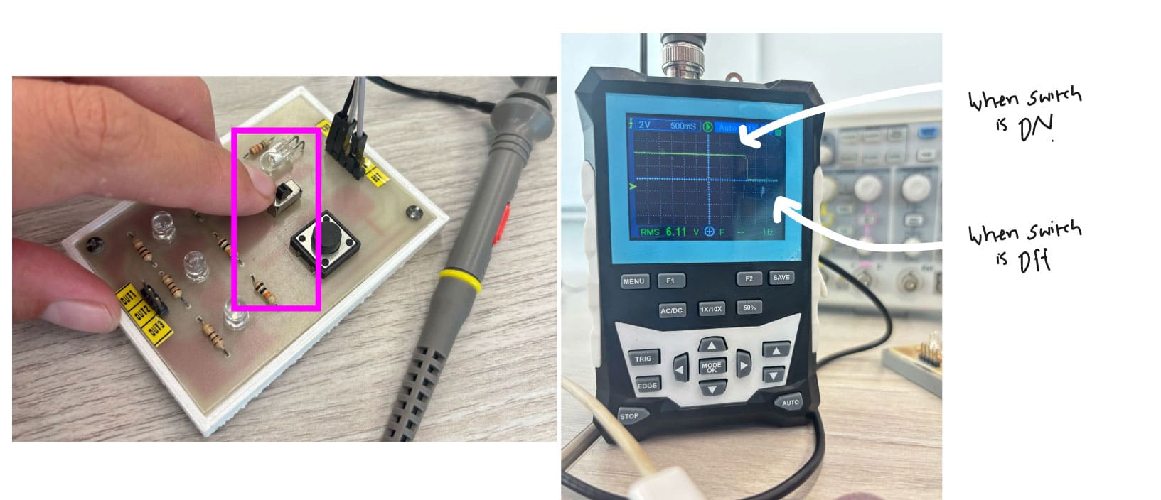
s w i t c h process
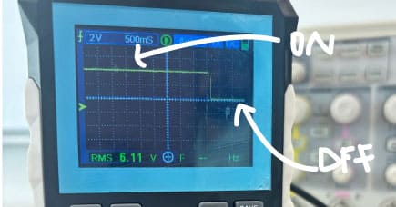 In the case of the switch it chaged from ON and OFF the same values as the DIO. From 0 to 4 voltage.

s w i t c h process
 In the case of the switch it chaged from ON and OFF the same values as the DIO. From 0 to 4 voltage.
 CONCLUSION:
The digital only reads SIGNALS as YES or NO. In this case 0 OR 4 as it only has two options whereas analog reads variable LEVELS and can be different values, that is why the line result changes from each example board.
INDIVIDUAL ASSIGNMENT
For this assignment I decided to make an small pcb board to connect to my previous pcb made in Week 8, so I can connect the sensors I wanted to try to be more organized when connecting cables.
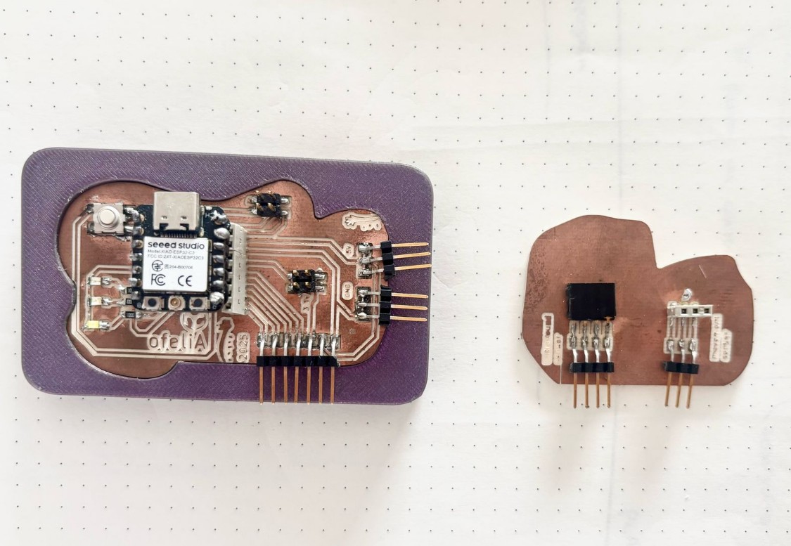
Week 8 pcb and new pcb for sensors
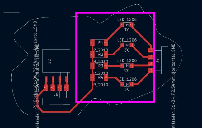
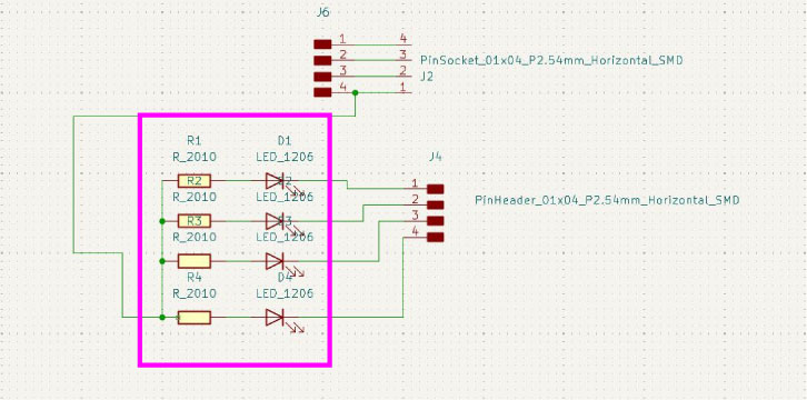
I first had the idea to make another pcb with lights to connect to my previous pcv where is the microcontroller. In this first idea I had 4 led lights connected to the free pins for the ultrasound sensor and another one for the movement sensor.
However my instructors told me to better use all the previous pcb board because in that I alredy had leds to try. So I discard this pcb design and make another one just with the free pins that each component need.
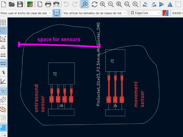
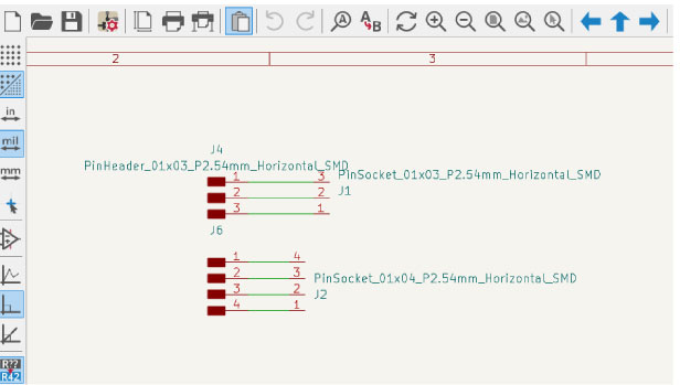
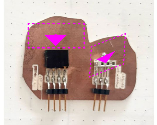
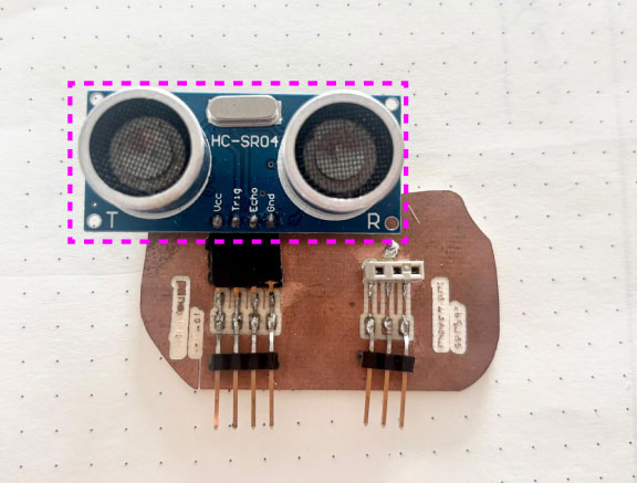
So, I made this pcb board where I just had the free pins for each component. What I did not think about was the size of each component. I left an space on the board thinking about putting there the sensor but it did not work as I wanted because it was bigger!. However it still works by connecting each sensor separated.
Personal assignments left by the local instructor
- Ultrasound sensor: Sold, connect and programm and read. ☑
- PIR sensor: Sold, connect and programm and read ☑
- Microphone: research what components it neads to make its pcb board and programm tests.
- Try another sensor like humidity.
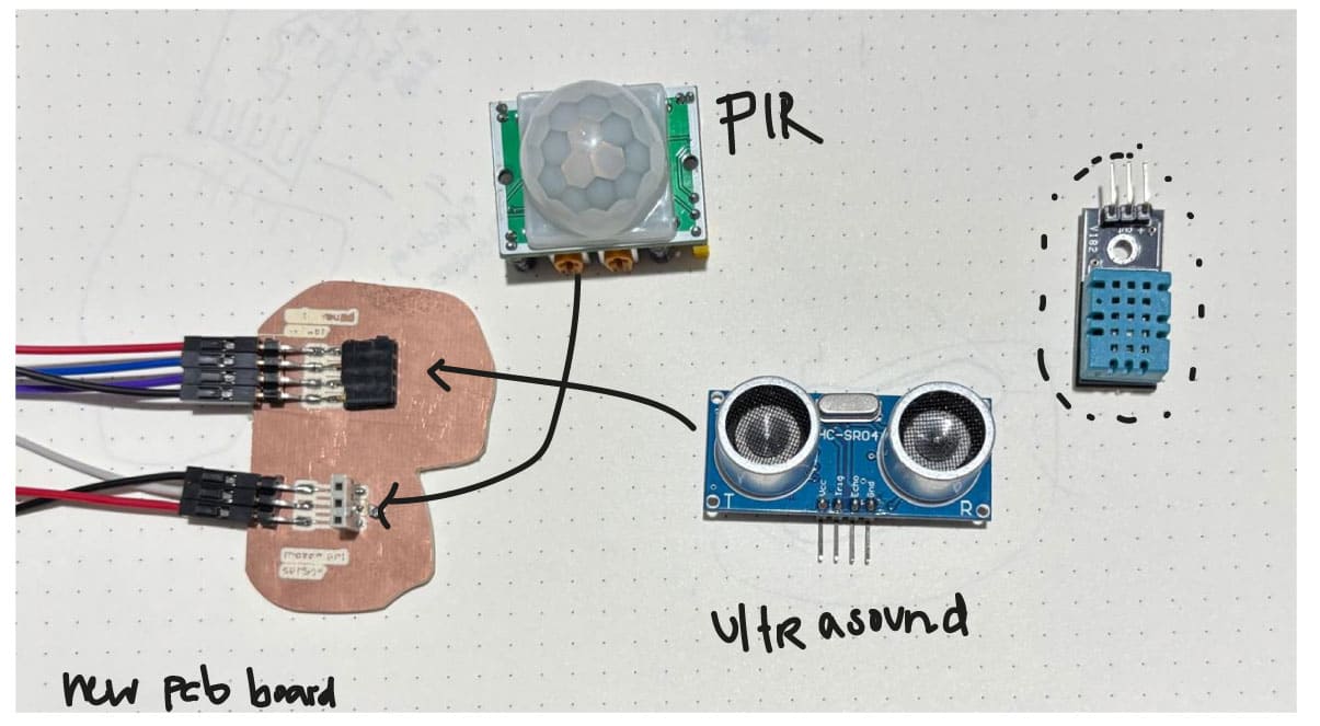
input sensors tested
1. U L T R A S O U N D input s e n s o r
To understand how the sensor works i found this tutorial/class from Rachel De Barros Youtube channel and blog which last one helped me understand the parts of the sensor and the code. I used my week 8 pcb board with some free pins and a new small pcb board so I can connect the sensor by this to my esp32-c3.
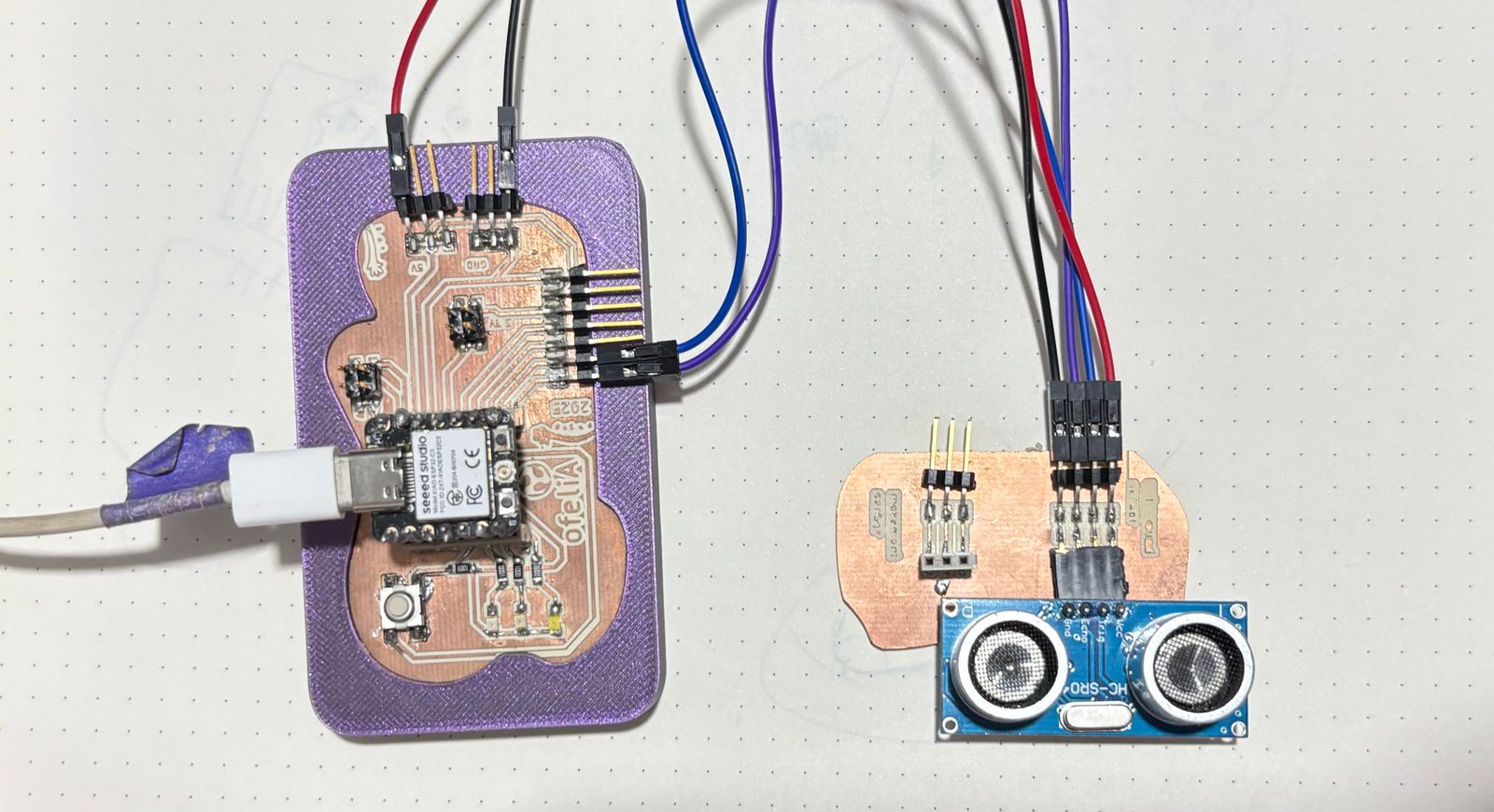
Pcb board and the ultrasound sensor connected
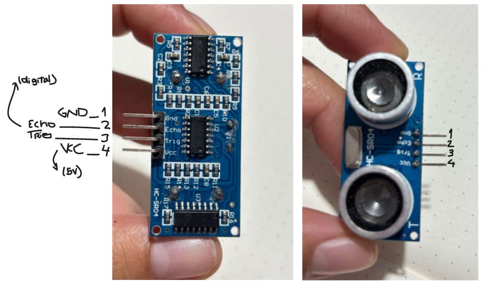
Ultrasound sensor component
This component measures distance by an imperceptible sound that travels till it touches an object which is measure by the time it takes for the sound to return. It needs 2 digital pins for TRIG AND ECHO.
From Rachel's blog:
Trig (Trigger): This pin is used to trigger ultrasonic sound pulses. By setting this pin to HIGH for 10µs from the Arduino, it causes the transmitter to send out an ultrasonic burst of eight short pulses at 40kHz that travel at the speed of sound. This unique 8-pulse pattern helps the receiver to distinguish between the transmitted pulses from ambient ultrasonic noise.
Echo: When the transmitter sends out its 8-pulse ultrasonic burst, the Echo pin goes HIGH and stays that way as it listens for the burst to reflect back. As soon as the reflected pulses come back to the receiver, the Echo pin goes LOW. By measuring the time the Echo pin stays HIGH, we can calculate the distance to the object that caused the bounce back. If there’s no object or reflected pulse, the Echo pin will time-out after 38ms and go back to a LOW state.
ULTRASOUND 1: Read the distance value on the serial monitor
First I connected the sensor to the pcb and just started the serial reading to see how it detects and measures distance. The code needs a variable for the distance.
const int trigPin = D8;
const int echoPin = D7;

float duration; // variable to store pulse duration
float distanceCM; // variable to store distance in CM
float distanceIN; // variable to store distance in IN

void setup() {
  Serial.begin(9600);
  pinMode(trigPin, OUTPUT);
  pinMode(echoPin, INPUT);
}

void loop() {
  // start with a clean signal
  digitalWrite(trigPin, LOW);
  delayMicroseconds(2);
  // send trigger signal
  digitalWrite(trigPin, HIGH);
  delayMicroseconds(10);
  digitalWrite(trigPin, LOW);
  // return pulse duration in microseconds
  // if set to HIGH, pulseIn() waits for the pin to go from LOW to HIGH
  // stops timing when pin goes back LOW
  duration = pulseIn(echoPin, HIGH);
  // convert m/s to in/microsec
  // 343 m/s = .034 cm/microseconds
  distanceCM = (duration * 0.034) / 2;
  // convert to inches, 1in = 2.54cm
  distanceIN = distanceCM / 2.54;
  // print distance to Serial Monitor
  Serial.print("Distance: ");
  Serial.print(distanceCM);
  Serial.print(" cm | ");
  Serial.print(distanceIN);
  Serial.println(" in");
  delay(100);
}
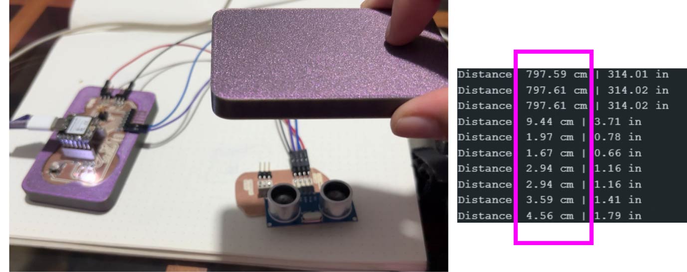
Ultrasound sensor serial
ULTRASOUND 2: Turn on lights by the distance
Then, I wanted it to turn on the 3 leds I had in the microcontroller board. By turning one led when distance is less than 10cm, then when is equal at 10cm and then if its more than 20cm.
const int trigPin = D8;
const int echoPin = D7;

const int led1 = D4;  // LED 1 (distancia corta)
const int led2 = D5;  // LED 2 (distancia media)
const int led3 = D6;  // LED 3 (distancia larga)

float duration; // variable para almacenar la duración del pulso
float distanceCM; // variable para almacenar la distancia en CM
float distanceIN; // variable para almacenar la distancia en IN

void setup() {
  Serial.begin(9600);

  // Configurar pines
  pinMode(trigPin, OUTPUT);
  pinMode(echoPin, INPUT);

  // Configurar pines de los LEDs como salida
  pinMode(led1, OUTPUT);
  pinMode(led2, OUTPUT);
  pinMode(led3, OUTPUT);

  // Asegúrate de que los LEDs estén apagados al inicio
  digitalWrite(led1, LOW);
  digitalWrite(led2, LOW);
  digitalWrite(led3, LOW);
}

void loop() {
  // Empezamos con una señal limpia
  digitalWrite(trigPin, LOW);
  delayMicroseconds(2);

  // Enviar la señal de activación
  digitalWrite(trigPin, HIGH);
  delayMicroseconds(10);
  digitalWrite(trigPin, LOW);

  // Medir la duración del pulso
  duration = pulseIn(echoPin, HIGH);

  // Calcular la distancia en centímetros
  distanceCM = (duration * 0.034) / 2;

  // Calcular la distancia en pulgadas
  distanceIN = distanceCM / 2.54;

  // Imprimir la distancia en el monitor serial
  Serial.print("Distancia: ");
  Serial.print(distanceCM);
  Serial.print(" cm | ");
  Serial.print(distanceIN);
  Serial.println(" in");

  // Apagar todos los LEDs antes de encender el adecuado
  digitalWrite(led1, LOW);
  digitalWrite(led2, LOW);
  digitalWrite(led3, LOW);

  // Encender LEDs según la distancia medida
  if (distanceCM  10) { // Si la distancia es menor que 10 cm
    digitalWrite(led1, HIGH); // Enciende el LED 1
  }
  else if (distanceCM >= 10  distanceCM  20) { // Si la distancia está entre 10 cm y 20 cm
    digitalWrite(led2, HIGH); // Enciende el LED 2
  }
  else if (distanceCM >= 20) { // Si la distancia es mayor o igual a 20 cm
    digitalWrite(led3, HIGH); // Enciende el LED 3
  }

  delay(100); // Esperar un momento antes de realizar otra medición
}
2. P I R input s e n s o r
As the other input, I used a tutorial from Rachel De Barros Youtube channel and this entrance of her blog. I also used my week 8 pcb board with some free pins and a new small pcb board so I can connect the sensor by this to my esp32-c3.
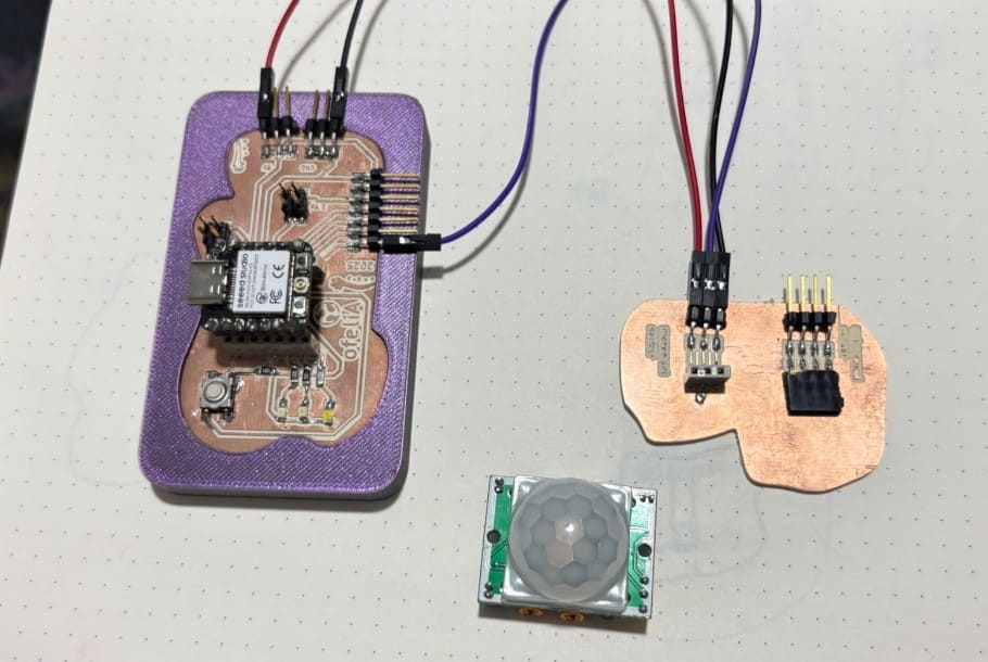
pcb board connections and PIR sensor
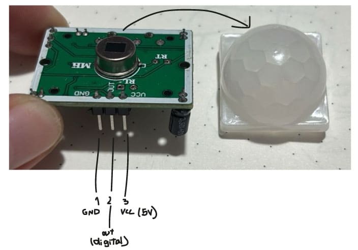
This component detects infrared radiation that is naturally emitted by living beings. This means that it reads the radiation that is increased when a human is by because of its temperature. It has a field of view of 100 degrees and needs 1 digital pin.
 On one side of the input component has like two keys that regulate the time delay and sensitivity of the sensor by how you rotate the small potenciometers it has.
From Rachel's blog:
Time Delay: Turning the potenciometer clockwise increases the duration that the sensor remains triggered after detecting motion, while turning it counter-clockwise decreases this duration. Time delays can typically range from a few seconds to several minutes, depending on the sensor model.
Sensitivity: Turning the sensitivity potentiometer clockwise increases sensitivity and expands the detection range, allowing the sensor to pick up smaller or more distant movements.
PIR 1: read the serial monitor from move detected or not
First I strated the serial read and programm the motion status as HIGH or LOW. This translates in detecting or not motion as it is seen in the serial monitor in the video.
int pirPin = D7; //Arduino pin the PIR sensor is connected to

int motionStatus = 0; // variable to store the PIR sensor's motion status (high or low)

void setup() {
  Serial.begin(9600); // initialize the serial monitor
  pinMode(pirPin, INPUT); // set the Arduino pin that PIR sensor is connected to as an INPUT
}

void loop() {
  motionStatus = digitalRead(pirPin); // read the PIR pin's current output (is it high or low?)

    // if the motion status is HIGH
    if (motionStatus == HIGH) {
      Serial.println("Motion Detected"); // print result to the serial monitor
    }

    //or else if motion status is low
    else {
      Serial.println ("Motion Ended"); //print result to the serial monitor
    }

    delay(100);  // optional delay to slow down the PIR sensor reading intervals
}
PIR 2: turn lights on by movement detection
Then I added to the same code the led pins from the microcontroller board and have 3 digital read and write for each led when motion starts and when motion ends.
int pirPin = D7;  // Pin de conexión del sensor PIR
int ledPin1 = D4; // Primer LED
int ledPin2 = D5; // Segundo LED
int ledPin3 = D6; // Tercer LED

int motionStatus = 0; // variable para almacenar el estado del sensor PIR (ALTO o BAJO)
int pirState = 0;     // variable para rastrear el cambio de estado

void setup() {
  Serial.begin(9600); // inicializar el monitor serial
  pinMode(pirPin, INPUT);  // establecer el pin del sensor PIR como ENTRADA

  // Configurar los pines de los LEDs como salidas
  pinMode(ledPin1, OUTPUT);
  pinMode(ledPin2, OUTPUT);
  pinMode(ledPin3, OUTPUT);

  // Asegurarse de que los LEDs estén apagados al principio
  digitalWrite(ledPin1, LOW);
  digitalWrite(ledPin2, LOW);
  digitalWrite(ledPin3, LOW);
}

void loop() {
  motionStatus = digitalRead(pirPin); // leer el valor del pin del PIR (¿es ALTO o BAJO?)

  // Si el estado del PIR es ALTO (detectar movimiento)
  if (motionStatus == HIGH) {
    if (pirState == LOW) {
      Serial.println("Motion Detected");  // Imprimir en el monitor serial
      // Encender los tres LEDs
      digitalWrite(ledPin1, HIGH);
      digitalWrite(ledPin2, HIGH);
      digitalWrite(ledPin3, HIGH);
      pirState = HIGH;  // Cambiar el estado a ALTO
    }
  }
  // Si el estado del PIR es BAJO (fin del movimiento)
  else {
    if (pirState == HIGH) {
      Serial.println("Motion Ended");  // Imprimir en el monitor serial
      // Apagar los tres LEDs
      digitalWrite(ledPin1, LOW);
      digitalWrite(ledPin2, LOW);
      digitalWrite(ledPin3, LOW);
      pirState = LOW;  // Cambiar el estado a BAJO
    }
  }

  delay(100);  // opcional: retrasa la lectura para evitar lecturas repetidas rápidas
}

