
Assignments
Group Assignment
- Compare the toolchains and development workflows for available embedded architectures.
Individual Assignment
- Browse through the data sheet for your microcontroller.
- Write a program for a microcontroller, and simulate its operation.
GROUP ASSIGNMENT
More specific detailed from the worked done with Ernesto Castro in Fab Lab Universidad de Lima here
Compare toolchains and d e v e l o p m e n t w o r k f l o w s
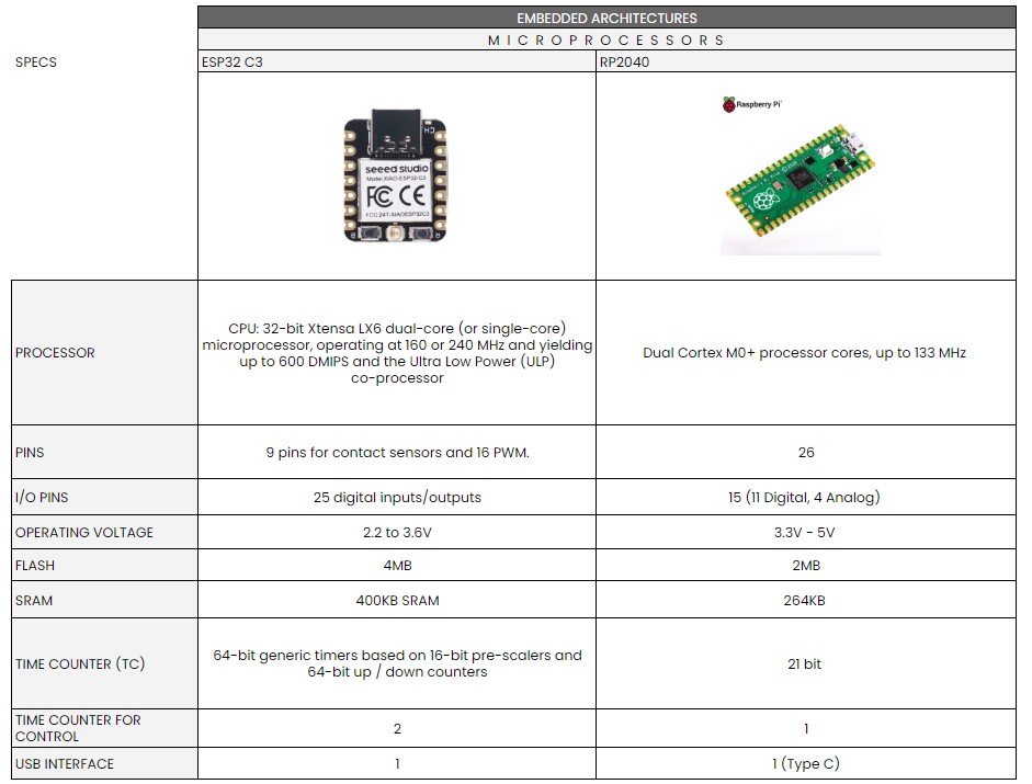
comparative microprocessors
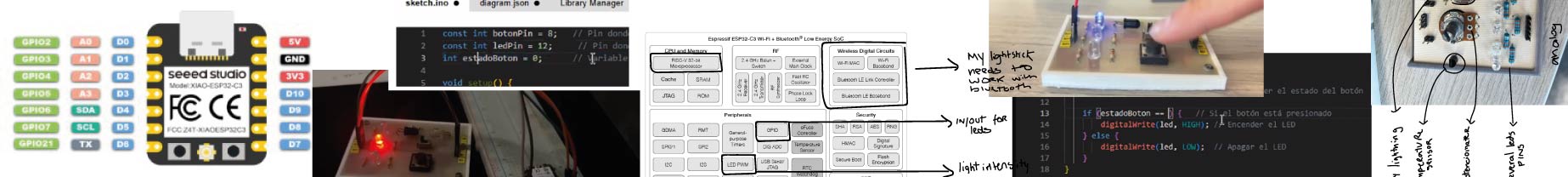
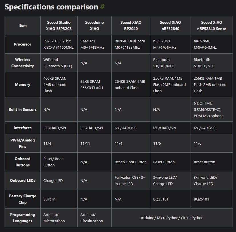
We chose to compare the ESP32-C3 processor in XIAO ESP32-C3 from Seeedspeed and RP2040 from Raspberry Pi because they were microcontrollers we had in the laboratory.
To understand their datasheets we first read it with our instructors and also check out some youtube tutorials to understand how to read it. Also I used some ChatGPT while at home to be sure about some terms.
XIAO ESP32-C3
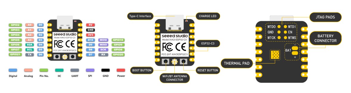
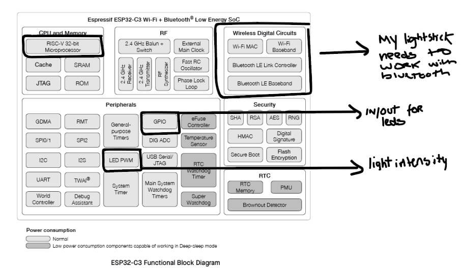
ESP32-C3 family is an ultra-low-power MCU-based SoC solution that supports 2.4 GHz Wi-Fi and Bluetooth®Low Energy (Bluetooth LE). It has 25 pins for digital and analog outputs.
Raspberry Pi RP2040
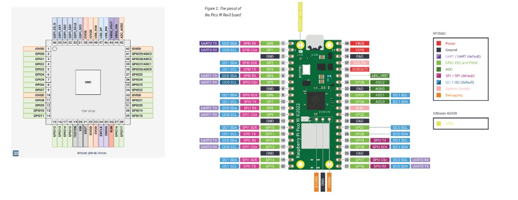
RP2040 has a dual M0+ processor cores, DMA, internal memory and peripheral blocks connected via AHB/APB bus fabric. It has 11 pins for digital outputs and 4 for analog.
c o m p a r i s o n
Some keys I understood from their datasheets:
Architectures:
Connectivity:
Workflows:
ESP32-C3 Data Sheet
Raspberry Pi RP2040 Data Sheet
INDIVIDUAL ASSIGNMENT
FIRST, what do you mean by Embedded Programming?
What is a microcontroller and a processor?
I did have experience once (5 years ago), programming a car with sensors. However I did it in a basic course with arduino where we just got to understand the programming codes.
What is E m b e d d e d Pr o g r a m m i n g ?
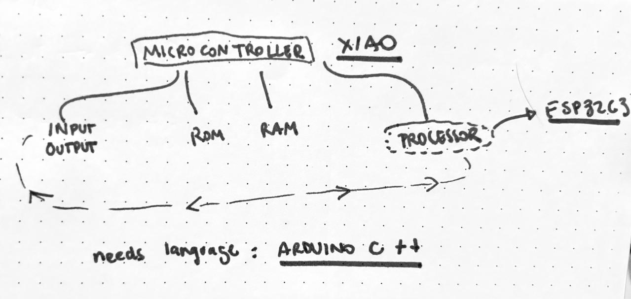
As always I had to make my own graphic to understand the steps. I got to understand embedded programming reffers to programming systems that are not computers but what its inside. And there are embedded systems to programm to make certain things. And it has components in which you have microcontrollers.
As said in the group assignment, I check out some youtube tutorials to understand how to read the datasheet and also asked ChatGPT to be sure about some terms.
It also came with a Software setup guide to install and first run the program. I also checked Ernesto Buendia repo Since he is one of my instructors now and had a specific guide so I don't make any mistake.
As always I had to make my own graphic to understand the steps. I got to understand embedded programming reffers to programming systems that are not computers but what its inside. And there are embedded systems to programm to make certain things. And it has components in which you have microcontrollers.
The microcontrollers work with a processor inside. I got to test the XIAO ESP32-C3. This is a development board made by Seeedstudio based in the ESP32-C3 microprocessor and I will work it with Arduino IDE based in the language C++.
XIAO ESP32 -C3 d a t a s h e e t
As said in the group assignment, I check out some youtube tutorials to understand how to read the datasheet and also asked ChatGPT to be sure about some terms.
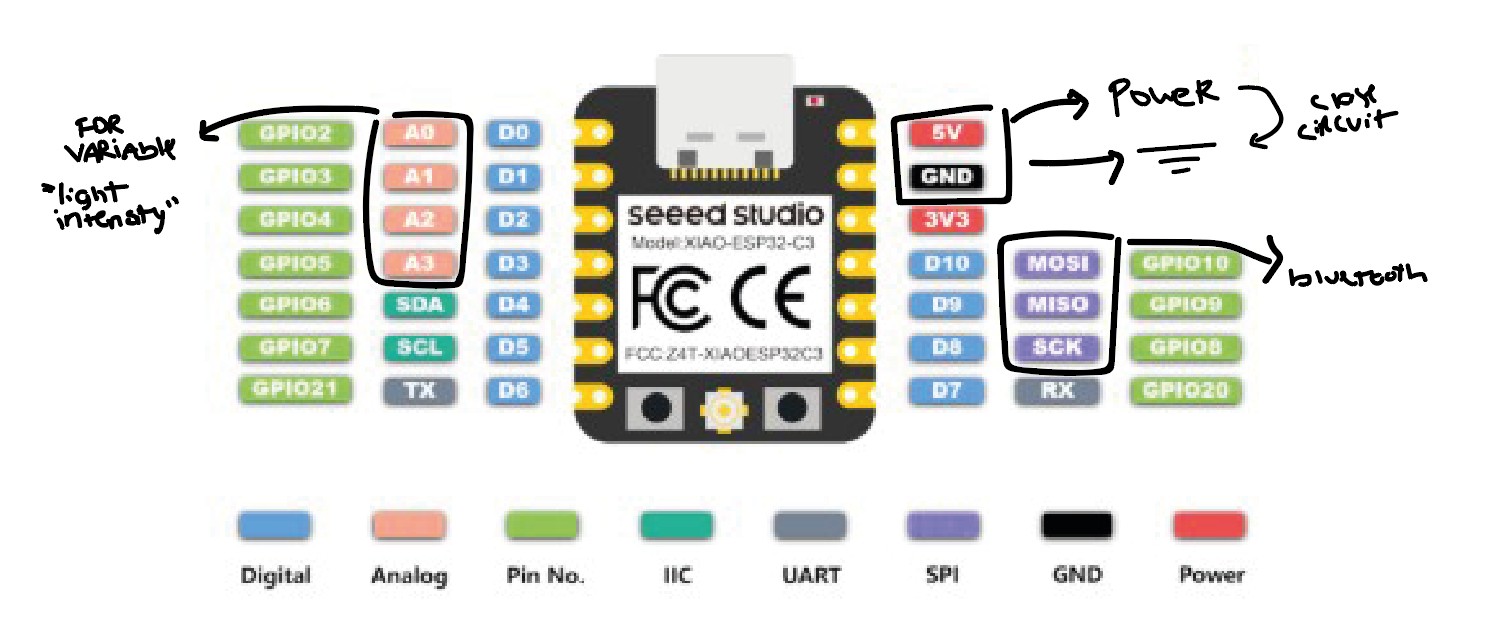
The first thing I recognise was how many pins can connect to analog and digital. Uderstanding analog means variable results while digital 1 or 0.
Then I also shearched for datasheet of the development board I will be using that is the XIAO ESP32-C3 by Seedstudio. This datasheet was easier since it comes with a Getting started webpage. where everything is very detailed. And I could understood the differences using this development board than others for the ESP32 family. And for the most important part, knowing the pins and for what connection is each.
It also came with a Software setup guide to install and first run the program. I also checked Ernesto Buendia repo Since he is one of my instructors now and had a specific guide so I don't make any mistake.
S E T U P g u i d e :
- Download Arduino IDE from here.
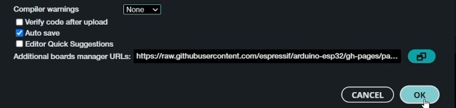
- Go to Preferences > Settings
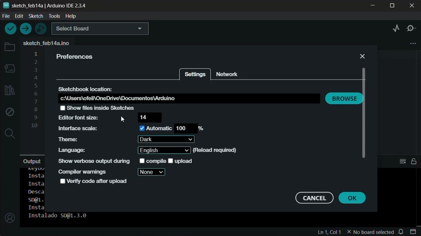
- Scroll down until "Additional Boards Manager URLs". Enter: https://files.seeedstudio.com/arduino/package_seeeduino_boards_index.json
- Install the board you are using: Tools > Board > ESP32 > XIAO ESP32C3
- Select the port (this will be available once you connect the USB cable to your laptop).
w r i t t i n g a program for the XIAO ESP32-C3
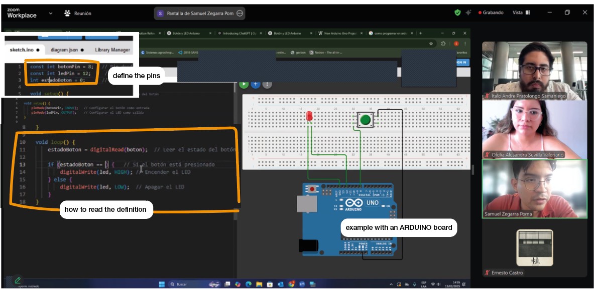
First, my instructors gave us an intro in programming while making a simulation in Wokwi.
Some important notes I took:
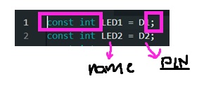
Start with definition. It is important to tell in which pin you will be working and don't forget that numers and capital letters do matter.
High is for ON and low for OFF
Serial communication is optional to see the variables
The protoboard works in two parts. The center in which the continuity is vertical. And the borders where the continuity is horizontal.
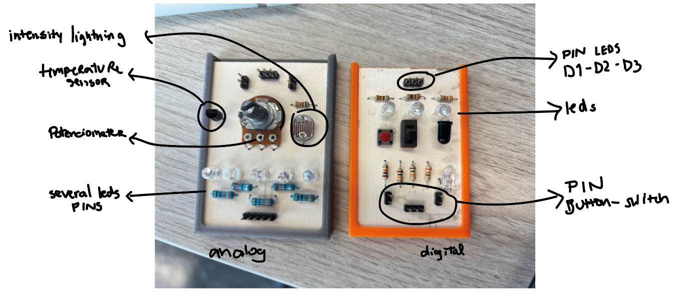
Then they gave us two boards to work with. One digital and one analog.
To first try and understand the programming.
Important advices:
- At the top is the toolbar to upload a code. First is to ✔️ check the code and see any errors. And then ➡️ to upload.

- HIGH is like YES/ON and LOW is like NO/OFF
- First in the code, tell your variables. The name to recognize them and the PIN where is connected. Keep in mind the capitals letters and the numbers.
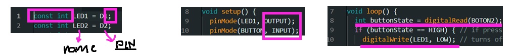
- Then in the set up tell which is the output and which the input in digital cases.
- And in the loop you tell how to read the variable and then what happens with it.
Simulating and T E S T I N G
My instructor recomend to start with simple leds with the digital and analog boards they have in the lab. Because a lot of the programming work on my lightstick will have to do with leds and controlling colors and modes of turning them on and off. Also using that boards because in the simulaton I can checked the resistors locations and connections.
p e r s o n a l A S S I G N M E N T S
- Task 1: turn the led on and off by 1 second.☑
- Task 2: turn the led on with a button.☑
- Task 3: turn the led on with a switch.☑
- Task 4: turn 3 leds on.☑
- Task 5: turn 3 leds on individually with a button.☑
- Task 6: turn on 1 to 3 leds depending on the intensity light read by the sensor.☑
- Task 7: try one analog by turning on 5 leds depending on the potentiometer.☑
TASK 1: Turn the led on and off by 1 second.
const int LED1 = D2; // PIN where is the LED
void setup() {
  pinMode(LED1, OUTPUT);
}
void loop() {
  digitalWrite(LED1, HIGH); // Turn on LED
  delay(1000); // wait 1 second
  digitalWrite(LED1, LOW); // Turn off LED
  delay(1000); // wait 1 second
}
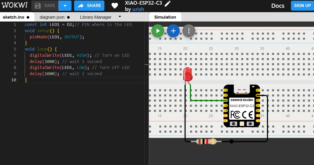
WOKWI Simulation
TASK 2: Turn the led on with a button.
Recuadro de Código
const int LED1 = D0;
const int BOTON2 =  D1;
void setup() {
  pinMode(LED1, OUTPUT);
  pinMode(BOTON2, INPUT);
}
void loop() {
  int buttonState = digitalRead(BOTON2); // Read button state
  if (buttonState == HIGH) { // if pressing the button
    digitalWrite(LED1, LOW); // turns off LED
  }
  else { // if not
    digitalWrite(LED1, HIGH); // turns on  LED
  }
}
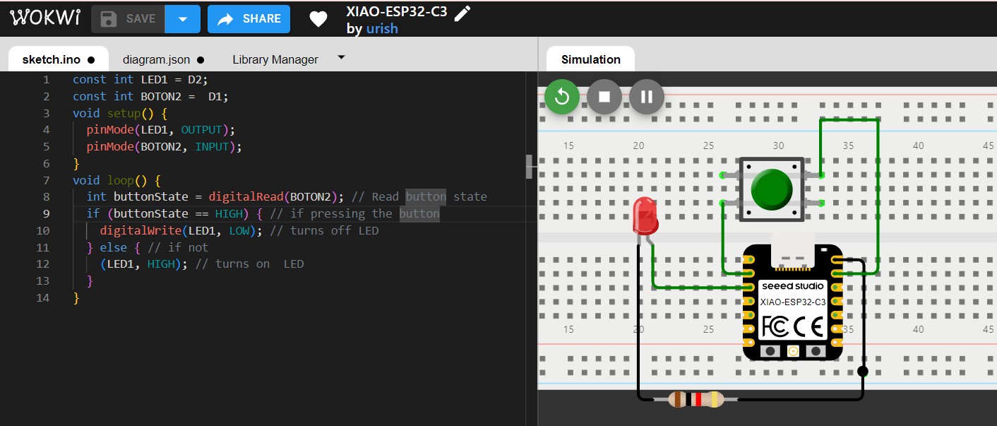
WOKWI Simulation
TASK 3: Turn the led on with a switch.
Recuadro de Código
const int LED = D0;
const int SWITCH = D1;

void setup() {
  pinMode(LED, OUTPUT);
  pinMode(SWITCH, INPUT);
}
void loop() {
  int switchState = digitalRead(SWITCH);

  if (switchState == HIGH) { // If pressing
    digitalWrite(LED, HIGH);  // turn on
  } else { // if not
    digitalWrite(LED, LOW);   // turn off
  }
}
TASK 4: Turn 3 leds on.
Recuadro de Código
const int LED1 = D0;
const int LED2 = D1;
const int LED3 = D2;

void setup() {
  pinMode(LED1, OUTPUT);
  pinMode(LED2, OUTPUT);
  pinMode(LED3, OUTPUT);
}

void loop() {
  digitalWrite(LED1, HIGH); // turns on LED 1
  delay(1000); // wait 1 sec
  digitalWrite(LED1, LOW); // turns off LED 1

  digitalWrite(LED2, HIGH); // turns on LED 2
  delay(1000); // wait 1 sec
  digitalWrite(LED2, LOW); // turns off LED 2

  digitalWrite(LED3, HIGH); // turns on el LED 3
  delay(1000); // wait 1 sec
  digitalWrite(LED3, LOW); // Aturns off LED 3
}
TASK 5: Turn 3 leds on individually with a button.
Recuadro de Código
const int LED1 = D0;
const int LED2 = D1;
const int LED3 = D2;
const int BOTON = D3;

int buttonState = 0;     // actual state
int lastButtonState = 0;
int pressCount = 0;      // pressing count
unsigned long lastDebounceTime = 0;
unsigned long debounceDelay = 50;

void setup() {
  pinMode(LED1, OUTPUT);
  pinMode(LED2, OUTPUT);
  pinMode(LED3, OUTPUT);
  pinMode(BOTON, INPUT);
}

void loop() {
  int reading = digitalRead(BOTON);

  // Si el estado ha cambiado
  if (reading != lastButtonState) {
    lastDebounceTime = millis();
  }

  if ((millis() - lastDebounceTime) > debounceDelay) {
    // Si el estado ha cambiado y ha pasado el tiempo de debouncing
    if (reading != buttonState) {
      buttonState = reading;

      // Solo incrementar el contador en la transición de LOW a HIGH
      if (buttonState == HIGH) {
        pressCount++;
        if (pressCount > 3) {
          pressCount = 1;
        }
      }
    }
  }

  lastButtonState = reading;

  // Controla los LEDs según el número de presiones del botón
  digitalWrite(LED1, pressCount >= 1 ? HIGH : LOW);
  digitalWrite(LED2, pressCount >= 2 ? HIGH : LOW);
  digitalWrite(LED3, pressCount >= 3 ? HIGH : LOW);
}
TASK 6: Turn on 1 to 3 leds depending on the intensity light read by the sensor.
Recuadro de Código
const int SENSORLUZ = A0; // where is the sensor. dont forget to be analog
const int LED1 = D1;
const int LED2 = D2;
const int LED3 = D3; // Leds
int sensorValue = 0; // variable from sensor

void setup() {
  Serial.begin(115200); //
    pinMode(LED1, OUTPUT);
    pinMode(LED2, OUTPUT);
    pinMode(LED3, OUTPUT);
    pinMode(SENSORLUZ, INPUT);
}

void loop() {
  sensorValue = analogRead(SENSORLUZ);
  Serial.print("Intensidad de luz: ");
  Serial.println(sensorValue);

  if (sensorValue < 2000) {  // if its below 2000 only turn on one led
    digitalWrite(LED1, HIGH);
    digitalWrite(LED2, LOW);
    digitalWrite(LED3, LOW);
  }
  else if (sensorValue >2000 && sensorValue <4050) {
    digitalWrite(LED1, HIGH);
    digitalWrite(LED2, HIGH);
    digitalWrite(LED3, LOW);
}
  else {
    digitalWrite(LED1, HIGH);
    digitalWrite(LED2, HIGH);
    digitalWrite(LED3, HIGH);
  }

  delay(1000); // wait 1 second between options
}
Dos Videos Juntos
In this analog case, It was important to start th serial read of the values. Also I had to know that this ESP32-C3 microcontroller model has 12-bit ADC (Analog-to-Digital Converter). So, it can produce 4096 possible values ONLY. So, the highest value in this case is 4095.
TASK 7: Try one analog by turning on 5 leds depending on the potentiometer.
const int LED1 = D1;
const int LED2 = D2;
const int LED3 = D3;
const int LED4 = D4;
const int LED5 = D5;
const int POT = A0;

void setup() {
  pinMode(LED1, OUTPUT);
  pinMode(BUTTON, INPUT);
}

void loop() {
  int potValue = analogRead(POT); // read the values
  int ledCount = map(potValue, 0, 1023, 0, 5); // from 0 to 5
turn on the leds
  digitalWrite(LED1, ledCount >= 1 ? HIGH : LOW);
  digitalWrite(LED2, ledCount >= 2 ? HIGH : LOW);
  digitalWrite(LED3, ledCount >= 3 ? HIGH : LOW);
  digitalWrite(LED4, ledCount >= 4 ? HIGH : LOW);
  digitalWrite(LED5, ledCount >= 5 ? HIGH : LOW);
}
Finally, it is important to remember that in the analog cases the pin changes from D to A. And you can connect two pins in the same A0 for analog and D0 for digital.
- Download Arduino IDE from here.
- Go to Preferences > Settings
- Scroll down until "Additional Boards Manager URLs". Enter: https://files.seeedstudio.com/arduino/package_seeeduino_boards_index.json
- Install the board you are using: Tools > Board > ESP32 > XIAO ESP32C3
- Select the port (this will be available once you connect the USB cable to your laptop).
w r i t t i n g a program for the XIAO ESP32-C3
First, my instructors gave us an intro in programming while making a simulation in Wokwi.
Some important notes I took:
Then they gave us two boards to work with. One digital and one analog.
To first try and understand the programming.
Important advices:
- At the top is the toolbar to upload a code. First is to ✔️ check the code and see any errors. And then ➡️ to upload.
- HIGH is like YES/ON and LOW is like NO/OFF
- First in the code, tell your variables. The name to recognize them and the PIN where is connected. Keep in mind the capitals letters and the numbers.
- Then in the set up tell which is the output and which the input in digital cases.
- And in the loop you tell how to read the variable and then what happens with it.
- Task 1: turn the led on and off by 1 second.☑
- Task 2: turn the led on with a button.☑
- Task 3: turn the led on with a switch.☑
- Task 4: turn 3 leds on.☑
- Task 5: turn 3 leds on individually with a button.☑
- Task 6: turn on 1 to 3 leds depending on the intensity light read by the sensor.☑
- Task 7: try one analog by turning on 5 leds depending on the potentiometer.☑
Simulating and T E S T I N G
My instructor recomend to start with simple leds with the digital and analog boards they have in the lab. Because a lot of the programming work on my lightstick will have to do with leds and controlling colors and modes of turning them on and off. Also using that boards because in the simulaton I can checked the resistors locations and connections.
My instructor recomend to start with simple leds with the digital and analog boards they have in the lab. Because a lot of the programming work on my lightstick will have to do with leds and controlling colors and modes of turning them on and off. Also using that boards because in the simulaton I can checked the resistors locations and connections.
p e r s o n a l A S S I G N M E N T S
TASK 1: Turn the led on and off by 1 second.
const int LED1 = D2; // PIN where is the LED void setup() { pinMode(LED1, OUTPUT); } void loop() { digitalWrite(LED1, HIGH); // Turn on LED delay(1000); // wait 1 second digitalWrite(LED1, LOW); // Turn off LED delay(1000); // wait 1 second }
WOKWI Simulation
TASK 2: Turn the led on with a button.
const int LED1 = D0; const int BOTON2 = D1; void setup() { pinMode(LED1, OUTPUT); pinMode(BOTON2, INPUT); } void loop() { int buttonState = digitalRead(BOTON2); // Read button state if (buttonState == HIGH) { // if pressing the button digitalWrite(LED1, LOW); // turns off LED } else { // if not digitalWrite(LED1, HIGH); // turns on LED } }
WOKWI Simulation
TASK 3: Turn the led on with a switch.
const int LED = D0; const int SWITCH = D1; void setup() { pinMode(LED, OUTPUT); pinMode(SWITCH, INPUT); } void loop() { int switchState = digitalRead(SWITCH); if (switchState == HIGH) { // If pressing digitalWrite(LED, HIGH); // turn on } else { // if not digitalWrite(LED, LOW); // turn off } }
TASK 4: Turn 3 leds on.
const int LED1 = D0; const int LED2 = D1; const int LED3 = D2; void setup() { pinMode(LED1, OUTPUT); pinMode(LED2, OUTPUT); pinMode(LED3, OUTPUT); } void loop() { digitalWrite(LED1, HIGH); // turns on LED 1 delay(1000); // wait 1 sec digitalWrite(LED1, LOW); // turns off LED 1 digitalWrite(LED2, HIGH); // turns on LED 2 delay(1000); // wait 1 sec digitalWrite(LED2, LOW); // turns off LED 2 digitalWrite(LED3, HIGH); // turns on el LED 3 delay(1000); // wait 1 sec digitalWrite(LED3, LOW); // Aturns off LED 3 }
TASK 5: Turn 3 leds on individually with a button.
const int LED1 = D0; const int LED2 = D1; const int LED3 = D2; const int BOTON = D3; int buttonState = 0; // actual state int lastButtonState = 0; int pressCount = 0; // pressing count unsigned long lastDebounceTime = 0; unsigned long debounceDelay = 50; void setup() { pinMode(LED1, OUTPUT); pinMode(LED2, OUTPUT); pinMode(LED3, OUTPUT); pinMode(BOTON, INPUT); } void loop() { int reading = digitalRead(BOTON); // Si el estado ha cambiado if (reading != lastButtonState) { lastDebounceTime = millis(); } if ((millis() - lastDebounceTime) > debounceDelay) { // Si el estado ha cambiado y ha pasado el tiempo de debouncing if (reading != buttonState) { buttonState = reading; // Solo incrementar el contador en la transición de LOW a HIGH if (buttonState == HIGH) { pressCount++; if (pressCount > 3) { pressCount = 1; } } } } lastButtonState = reading; // Controla los LEDs según el número de presiones del botón digitalWrite(LED1, pressCount >= 1 ? HIGH : LOW); digitalWrite(LED2, pressCount >= 2 ? HIGH : LOW); digitalWrite(LED3, pressCount >= 3 ? HIGH : LOW); }
TASK 6: Turn on 1 to 3 leds depending on the intensity light read by the sensor.
const int SENSORLUZ = A0; // where is the sensor. dont forget to be analog const int LED1 = D1; const int LED2 = D2; const int LED3 = D3; // Leds int sensorValue = 0; // variable from sensor void setup() { Serial.begin(115200); // pinMode(LED1, OUTPUT); pinMode(LED2, OUTPUT); pinMode(LED3, OUTPUT); pinMode(SENSORLUZ, INPUT); } void loop() { sensorValue = analogRead(SENSORLUZ); Serial.print("Intensidad de luz: "); Serial.println(sensorValue); if (sensorValue < 2000) { // if its below 2000 only turn on one led digitalWrite(LED1, HIGH); digitalWrite(LED2, LOW); digitalWrite(LED3, LOW); } else if (sensorValue >2000 && sensorValue <4050) { digitalWrite(LED1, HIGH); digitalWrite(LED2, HIGH); digitalWrite(LED3, LOW); } else { digitalWrite(LED1, HIGH); digitalWrite(LED2, HIGH); digitalWrite(LED3, HIGH); } delay(1000); // wait 1 second between options }
In this analog case, It was important to start th serial read of the values. Also I had to know that this ESP32-C3 microcontroller model has 12-bit ADC (Analog-to-Digital Converter). So, it can produce 4096 possible values ONLY. So, the highest value in this case is 4095.
TASK 7: Try one analog by turning on 5 leds depending on the potentiometer.
const int LED1 = D1; const int LED2 = D2; const int LED3 = D3; const int LED4 = D4; const int LED5 = D5; const int POT = A0; void setup() { pinMode(LED1, OUTPUT); pinMode(BUTTON, INPUT); } void loop() { int potValue = analogRead(POT); // read the values int ledCount = map(potValue, 0, 1023, 0, 5); // from 0 to 5 turn on the leds digitalWrite(LED1, ledCount >= 1 ? HIGH : LOW); digitalWrite(LED2, ledCount >= 2 ? HIGH : LOW); digitalWrite(LED3, ledCount >= 3 ? HIGH : LOW); digitalWrite(LED4, ledCount >= 4 ? HIGH : LOW); digitalWrite(LED5, ledCount >= 5 ? HIGH : LOW); }