Week 4
Embedded Programming
My particular task for FabAcademy's fourth week was to look through the microcontroller datasheet. In order to interact (with local input and/or output devices) and communicate (with a remote wired or wireless connection), I will write a program for a microcontroller and simulate its operation. Implementing programming protocols is what I'm going to study.
My Hero Shot for this Week

Introduction:
Writing software that communicates directly with hardware in circumstances with limited resources is known as embedded programming, or EP. Sensors, motors, displays, and communication modules are among the gadgets that are controlled by microcontrollers or embedded processors. Due to limited hardware capabilities, programs—which are frequently written in C or C++—need to be optimized for speed, memory utilization, and power efficiency. Real-time operations are common for embedded systems, necessitating prompt and dependable reactions to outside events. Firmware is the permanent program stored in flash memory, and developers examine and troubleshoot it using debugging tools like serial monitors and JTAG/SWD interfaces. Protocols like I2C, SPI, and UART, as well as wireless techniques like Bluetooth and Wi-Fi, are frequently used to communicate with other devices. IoT, robotics, automotive systems, industrial automation, and consumer electronics are just a few of the fields where EP is vital. Power management is particularly important for battery-powered applications.
What is embedded programming:
Embedded programming involves writing software for specialized computers (like microcontrollers and microprocessors) that are embedded within other devices or systems. These systems are designed to perform specific functions, unlike general-purpose computers that handle a wide range of tasks. Embedded programming is crucial in various industries, including automotive, consumer electronics, and industrial automation.
Key Characteristics of Embedded Programming:
Embedded Programming Languages:
Click to know more about Embedded Programming
Group Assignment:
- we Demonstrated and compare the toolchains and development workflows for available embedded architectures
- we Document our work to the group work page.
- Linked to the group assignment page.
Click to open our Group Assignment
Outcomes
Group assignments:
To Demonstrated and compare the toolchains and development workflows for available embedded architectures
Document the work to the group work page and reflect on your individual page what you learned
Individual assignments:
Browse through the datasheet for your microcontroller
Write a program for a microcontroller, and simulate its operation, to interact (with local input &/or output devices) and communicate (with remote wired or wireless connection)


How Embedded Programming Works:
1. Understand the Hardware
Example: An Arduino board connected to an LED.
2. Write the Code
Example (Arduino – Blink LED):
                 void setup() {
                 pinMode(13, OUTPUT);  // Set pin 13 as output
                    }

                void loop() {
                digitalWrite(13, HIGH); // Turn on LED
                delay(1000);            // Wait 1 second
                digitalWrite(13, LOW);  // Turn off LED
                delay(1000);            // Wait 1 second
                }
Explanation of LED Blink Code
- Setup Function setup() – Configures pin 13 as an output to control the LED. Ensures the microcontroller knows that pin 13 will send voltage signals.
- Main Loop loop() – Continuously repeats the actions defined inside it, forming the core of the program.
- Turning the LED ON – Sets pin 13 HIGH, supplying voltage to the LED, which causes it to light up.
- Delay After Turning ON – Waits 1 second (1000 milliseconds) to keep the LED on long enough to be visible.
- Turning the LED OFF – Sets pin 13 LOW, cutting voltage to the LED, which turns it off.
- Delay After Turning OFF – Waits 1 second before repeating the loop, creating a visible blink effect.
- Summary – Produces a simple blinking LED effect, demonstrating basic digital output control and timing. Serves as a foundational example for learning microcontroller programming.
3. Compile the Code
4. Upload to the Microcontroller
5. Execution Begins
main() or setup() function.6. Hardware Interacts with Code
Your code controls the physical components:
- Turns on/off LEDs
- Reads button presses
- Sends/receives signals (e.g., via UART, I2C, SPI)
- Controls motors, displays, etc.
Example Flow (Blinking LED)
| Step | Action |
|---|---|
| Hardware Setup | Arduino + LED on pin 13 |
| Write Code | LED blink code in Arduino IDE |
| Compile | Translates C++ into machine code |
| Upload | Program is flashed onto Arduino |
| Run | LED blinks on and off every second |
Datasheet Microcontroller
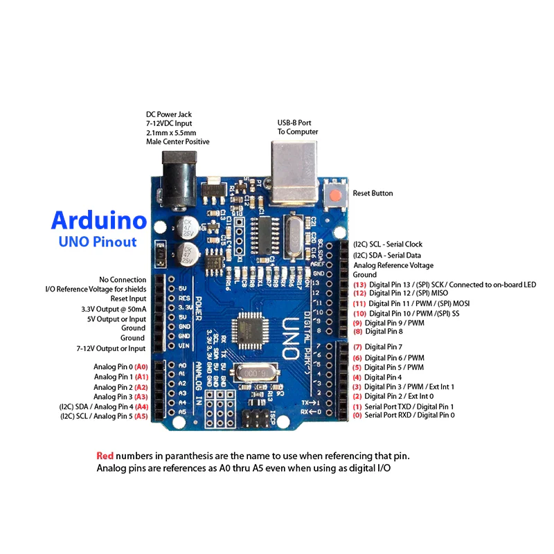
Arduino Uno R3 Datasheet :
The ATmega328P serves as the foundation for the Arduino Uno R3 microcontroller board. Because of its open-source nature, cost, and ease of use, it is frequently utilized for electronics projects and prototyping.
Technical Specifications :
Microcontroller: ATmega328P
Operating Voltage: 5V
Input Voltage (recommended): 7-12V
Input Voltage (limits): 6-20V
Digital I/O Pins: 14 (6 provide PWM output)
Analog Input Pins: 6
DC Current per I/O Pin: 20 mA
Flash Memory: 32 KB (0.5 KB used by bootloader)
SRAM: 2 KB
EEPROM: 1 KB
Clock Speed: 16 MHz
Connectivity: USB Type-B
Communication: UART, SPI, I2C
Dimensions: 68.6 mm × 53.4 mm
Weight: ~25 g
Arduino Uno R3 Pin Details :
The Arduino Uno R3 has various types of pins categorized into Digital I/O, Analog Input, Power, and Communication pins. Here’s a detailed breakdown of each pin’s function and usage.
Digital I/O Pins (D0 - D13):
These pins can be used as either input or output using pinMode().
Operate at 5V logic level and can handle up to 40mA per pin.
Some pins have special functions for communication, PWM, or interrupts.
Pin-by-Pin Explanation:
D0 (RX) – Used to receive serial data (UART communication). Avoid using this pin if you're using Serial Monitor.
D1 (TX) – Used to transmit serial data (UART communication). Avoid using this pin if you're using Serial Monitor.
D2 – General-purpose digital I/O. Can also be used as an external interrupt (attachInterrupt()).
D3 – Supports PWM (Pulse Width Modulation) and can be used for motor speed control, LED dimming, etc. Also supports external interrupts.
D4 – General-purpose digital I/O pin.
D5 – Supports PWM. Useful for motor drivers and LED brightness control.
D6 – Supports PWM. Similar to D5, often used in analog output applications.
D7 – General-purpose digital I/O pin.
D8 – General-purpose digital I/O pin.
D9 – Supports PWM. Often used for motor control, servos, and dimming LEDs.
D10 – Supports PWM and also serves as SPI Slave Select (SS) for SPI communication.
D11 – Supports PWM and is used for SPI Master Out Slave In (MOSI) communication.
D12 – Used for SPI Master In Slave Out (MISO) communication.
D13 – Used for SPI Serial Clock (SCK) and also controls the built-in LED on the board.
Analog Input Pins (A0 - A5):
These pins are 10-bit Analog-to-Digital Converters (ADC), meaning they convert analog signals (0-5V) into values between 0-1023.
Can also be used as digital I/O if required.
Pin-by-Pin Explanation
A0 – Reads analog signals, e.g., from sensors like temperature or light sensors.
A1 – Similar to A0, used for measuring varying voltage levels.
A2 – Used for additional sensor readings.
A3 – General-purpose analog input pin.
A4 – Can be used for I2C communication (SDA - Serial Data Line).
A5 – Can be used for I2C communication (SCL - Serial Clock Line).
Power Pins:
Used to power the board and connected components like sensors, motors, and displays.
Pin-by-Pin Explanation
VIN – Used to supply external power (7-12V recommended, max 20V). The onboard regulator converts it to 5V.
3.3V – Provides a regulated 3.3V output for low-power components like some sensors.
5V – Provides a regulated 5V output from the onboard voltage regulator.
GND (Ground) – Common ground reference for circuits (Multiple GND pins available).
AREF (Analog Reference) – Used to provide a reference voltage for analog inputs, improving precision.
IOREF – Provides a reference voltage (5V) to shields for compatibility.
Communication Pins:
These pins are used for data transmission between the Arduino and other devices (e.g., sensors, displays, computers).
Serial Communication UART ( Universal Asynchronous Receiver Transmitter)
D0 (RX) – Serial receive pin (receives data from another device).
D1 (TX) – Serial transmit pin (sends data to another device).
SPI Communication (Serial Peripheral Interface)
D10 (SS - Slave Select) – Used to select slave devices in SPI communication.
D11 (MOSI - Master Out Slave In) – Sends data from the Arduino to connected SPI devices.
D12 (MISO - Master In Slave Out) – Receives data from an SPI device.
D13 (SCK - Serial Clock) – Provides the clock signal for SPI communication.
I2C Communication (Inter-Integrated Circuit)
A4 (SDA - Serial Data Line) – Used for data exchange in I2C communication.
A5 (SCL - Serial Clock Line) – Generates the clock signal for I2C communication.
Summary:
Digital Pins (D0-D13): General-purpose I/O, PWM, interrupts, UART, SPI.
Analog Pins (A0-A5): Read analog sensors, can also be used as digital pins, support I2C.
Power Pins: Provide power to circuits and components (VIN, 3.3V, 5V, GND, AREF).
Communication Pins: Enable Serial (UART), SPI, and I2C communication.
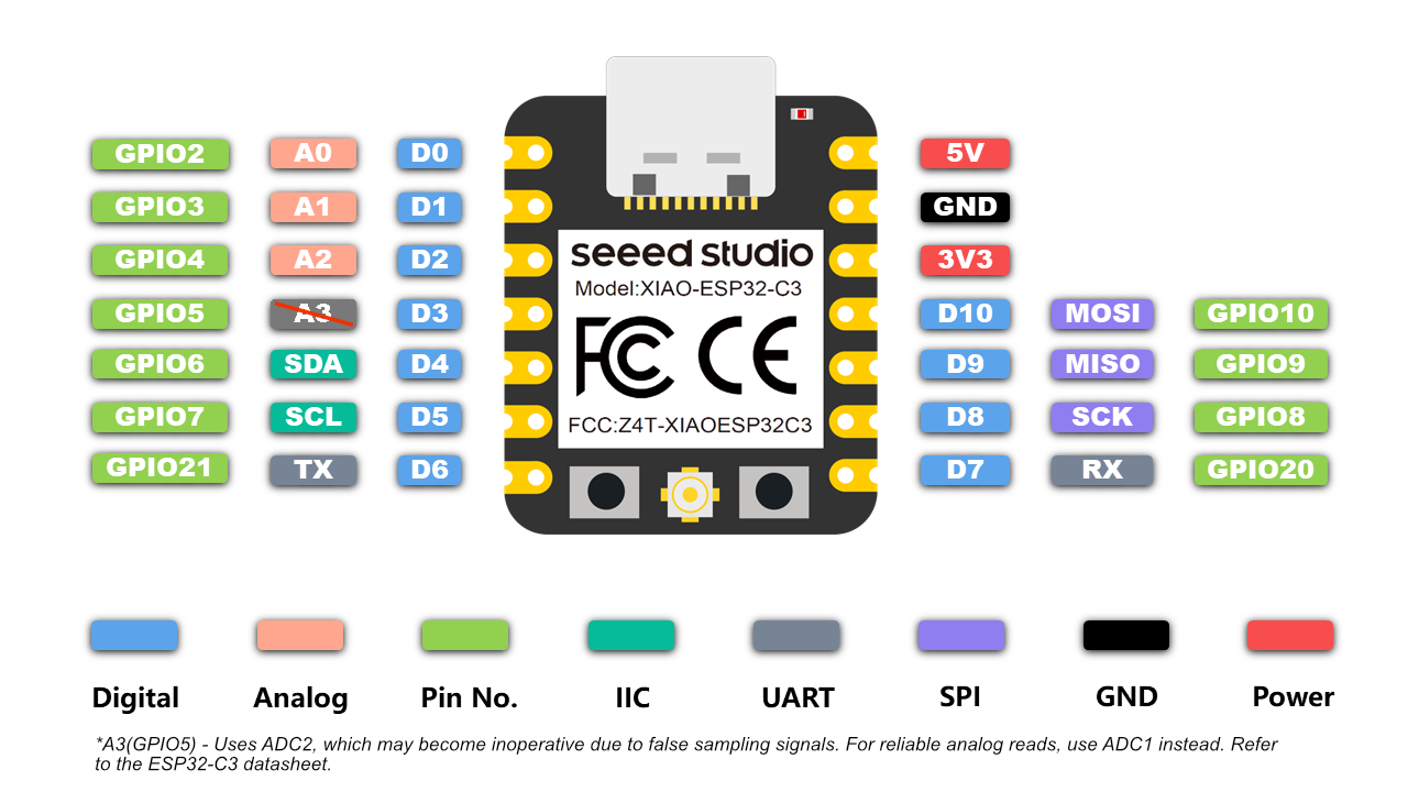
ESP32-C3 Datasheet:
The ESP32-C3 is a cost-effective, low-power, 32-bit RISC-V microcontroller with integrated Wi-Fi and Bluetooth LE 5.0. Designed for secure and efficient IoT applications, it provides robust wireless connectivity and flexible I/O configuration.
Technical Specifications:
Microcontroller: 32-bit RISC-V Single-Core CPU
Clock Speed: Up to 160 MHz
SRAM: 400 KB
ROM: 384 KB
Flash: External (typically 4 MB via SPI)
EEPROM: Not available (can be emulated using flash)
Operating Voltage: 3.0V to 3.6V
Input Voltage (recommended): Via 3.3V regulated supply
Wi-Fi: IEEE 802.11 b/g/n (2.4 GHz, up to 150 Mbps)
Bluetooth: Bluetooth 5.0 LE with Mesh and Long Range
Digital I/O Pins: 22 GPIOs
ADC: 12-bit, up to 6 channels
UART: 2
SPI: 2
I2C: 1
PWM: Available on all GPIOs
Timers: Multiple hardware timers
USB: USB 2.0 Full-Speed (native support)
Security: AES, SHA, RSA, ECC, Flash Encryption, Secure Boot
Power Consumption: Active Mode ~130 mA, Light Sleep ~0.8 mA, Deep Sleep ~5 µA
Package: QFN32 (5 mm × 5 mm)
Supported Tools: ESP-IDF, Arduino IDE, PlatformIO, MicroPython
ESP32-C3 Pin Details:
The ESP32-C3 supports flexible pin assignment using its GPIO matrix, allowing peripherals to be remapped to available pins as needed.
Digital I/O Pins (GPIO0 to GPIO21)
All GPIOs are multifunctional and support input, output, pull-up/down, PWM, and peripheral mapping. Maximum current draw per GPIO is approximately 20–40 mA depending on usage.
Important GPIOs
GPIO0 – Used for boot mode selection during flashing
GPIO1 and GPIO3 – Default UART TX and RX (avoid using when Serial Monitor is active)
GPIO9 and GPIO10 – Usually connected to internal flash, should not be used for I/O
GPIO19 and GPIO20 – USB D- and D+ on some modules
Analog Input Pins (ADC1 Channels)
ESP32-C3 has 6 ADC1 channels with 12-bit resolution, mapped to GPIOs like GPIO0 to GPIO5. These are used for reading analog voltages from 0 to 3.3V.
Power Pins:
3V3 – Regulated 3.3V power input
GND – Ground reference
EN – Chip enable (reset if pulled low)
VBUS – USB power input (5V on USB)
LDO Cap – Capacitor pin for internal LDO regulator (used in specific modules)
Communication Pins:
Serial (UART): Default UART uses GPIO1 (TX) and GPIO3 (RX). UARTs can be remapped to other pins using software.
SPI: SPI0 is reserved for internal flash. SPI1 is available for general-purpose communication and can be mapped to any free GPIOs.
I2C: Supports one I2C controller in master/slave mode. SDA and SCL lines can be assigned to most GPIOs. Common assignments are GPIO4 (SDA) and GPIO5 (SCL).
USB: Native USB 2.0 interface supported on modules like ESP32-C3-DevKit. D+ and D- are usually mapped to GPIO19 and GPIO20.
Security Features:
Hardware-based Flash Encryption
Secure Boot (version 2)
Cryptographic acceleration for AES-128/256, SHA-2, RSA-3072, and ECC
Digital Signature Peripheral
Summary:
Digital Pins (GPIO0–GPIO21): General-purpose I/O with PWM and peripheral mapping
Analog Pins: 6 channels of 12-bit ADC
Power Pins: 3.3V input, multiple GND, EN, USB VBUS
Communication Interfaces: UART, SPI, I2C, USB
Connectivity: Integrated Wi-Fi (2.4 GHz) and Bluetooth 5.0 LE
Security: Supports advanced encryption, secure boot, and digital signature
Power Modes: Active (~130 mA), Light Sleep (~0.8 mA), Deep Sleep (~5 µA)
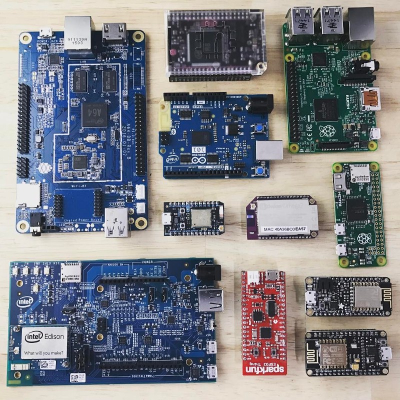
some other micro controllers
For Coding
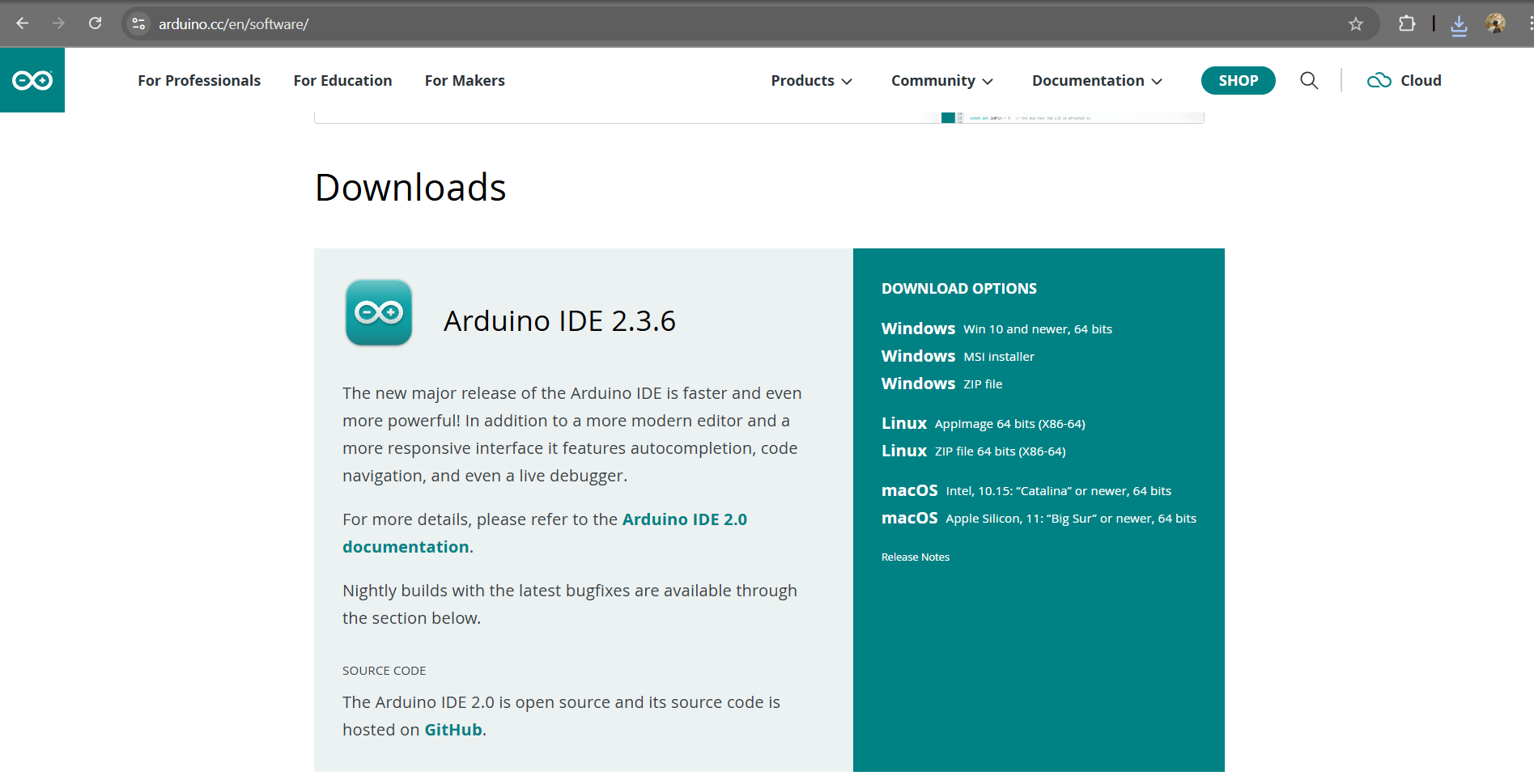
Arduino IDE :
For coding and uploading programs to my microcontroller, I am using the Arduino IDE. It is a user-friendly open-source platform that supports various boards like the ESP32-C3. With the help of its built-in libraries and community support, I can easily write, verify, and upload code to test different hardware functionalities
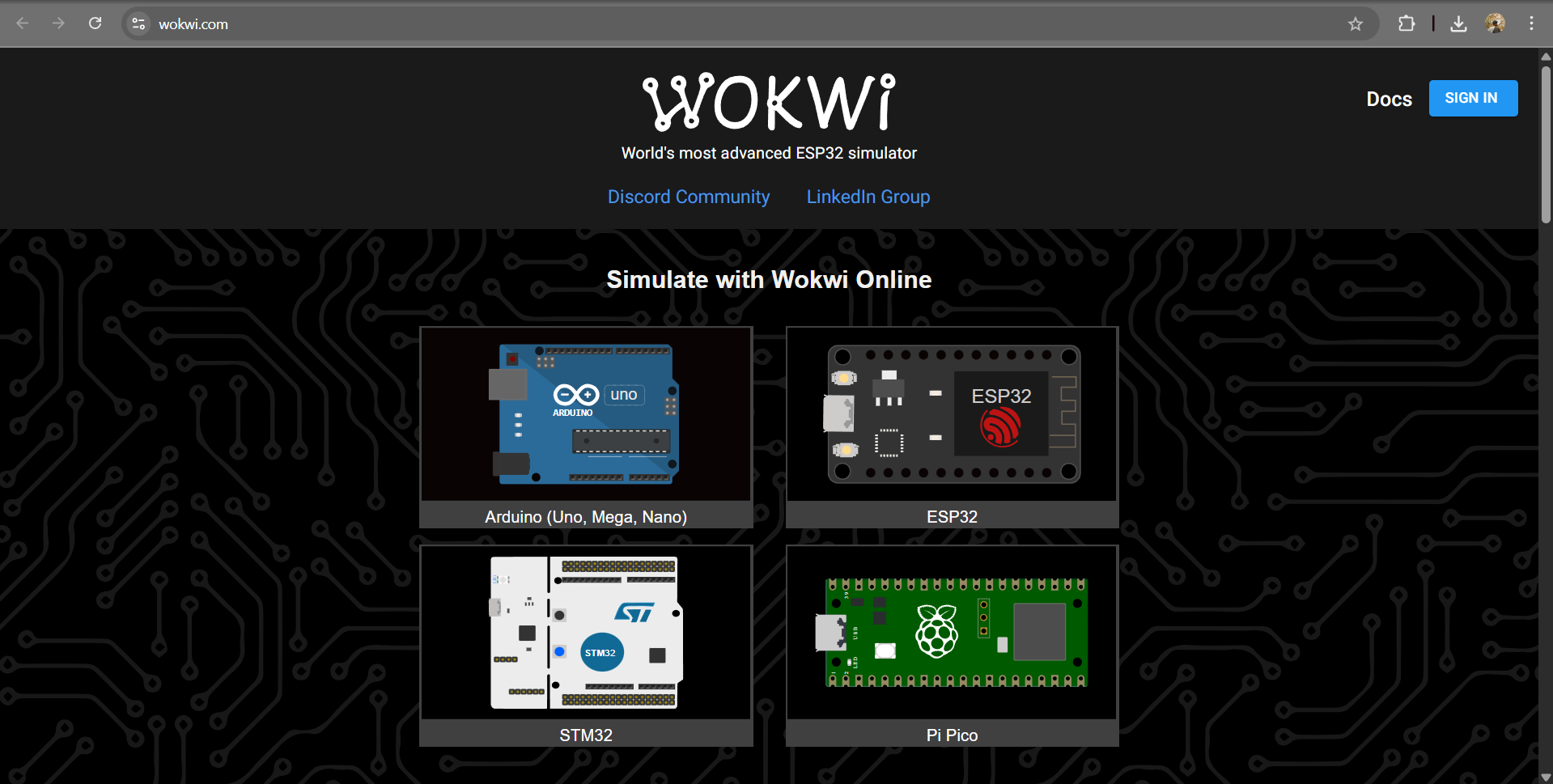
Wokwi Introduction :
Wokwi is an online simulator designed for developing and testing Arduino, ESP32, Raspberry Pi Pico, and other microcontroller-based projects. It allows users to create circuits, write code, and see real-time simulations in a browser without the need for physical hardware. Wokwi supports popular components like LEDs, sensors, displays, and more, making it an excellent tool for prototyping and learning embedded systems quickly and interactively.
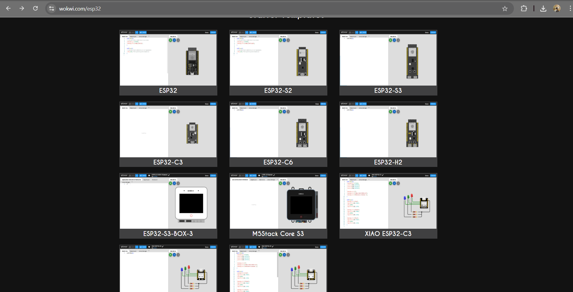
As part of the embedded programming assignment, I worked with the ESP32-C3 module integrated with the MPU6050 sensor. I explored I2C communication to read accelerometer and gyroscope data. This setup helped me understand real-time motion sensing and sensor interfacing, laying the foundation for integrating it into my final project.
Coding Part :
To interface the MPU6050 sensor with my ESP32-C3 board, I used the Adafruit MPU6050 library in the Arduino IDE. This library simplifies communication with the sensor by providing easy-to-use functions for accessing accelerometer and gyroscope data. After installing the library through the Library Manager, I was able to write and upload code to read motion and orientation values effectively.
Arduino library for the MPU6050 sensors
             #include <Adafruit_MPU6050.h> // Include the library for MPU6050 sensor
#include <Adafruit_Sensor.h>   // Include Adafruit sensor support
#include <Wire.h>              // I2C communication library
Adafruit_MPU6050 mpu;          // Create an MPU6050 sensor object
sensors_event_t event;         // Define a variable to hold sensor data
void setup() {
  Serial.begin(115200);       // Start serial communication at 115200 baud
  pinMode(D2, OUTPUT);        // Set pin D2 as OUTPUT (e.g., for LED or other output)
  pinMode(D3, OUTPUT);        // Set pin D3 as OUTPUT
  Serial.println("");
  Serial.println("Hello, XIAO ESP32-C3!"); // Welcome message
  Serial.println("Welcome to Wokwi :-)");
  while (!mpu.begin()) {      // Keep trying until MPU6050 initializes
    Serial.println("MPU6050 not connected!"); // Error message
    delay(1000);              // Wait for 1 second before retrying
  }
  Serial.println("MPU6050 ready!"); // MPU6050 successfully initialized
}
void loop() {
  // The following commented lines were for testing LEDs on different pins
  // Serial.println("Red");
  // digitalWrite(D2, HIGH);   // Turn on LED on D2
  // delay(500);               // Wait for 0.5 seconds
  // digitalWrite(D2, LOW);    // Turn off LED
  // Serial.println("Green");
  // digitalWrite(D3, HIGH);   // Turn on LED on D3
  // delay(500);
  // digitalWrite(D3, LOW);    // Turn off LED
  // Serial.println("Blue");
  // digitalWrite(D4, HIGH);   // This line would cause an error unless D4 is defined
  // delay(500);
  // digitalWrite(D4, LOW);
  mpu.getAccelerometerSensor()->getEvent(&event); // Read acceleration data
  Serial.print("[");
  Serial.print(millis());           // Print current time in milliseconds
  Serial.print("] X: ");
  Serial.print(event.acceleration.x); // Print X-axis acceleration
  Serial.print(", Y: ");
  Serial.print(event.acceleration.y); // Print Y-axis acceleration
  Serial.print(", Z: ");
  Serial.print(event.acceleration.z); // Print Z-axis acceleration
  Serial.println(" m/s^2");         // Print units
  delay(500);                       // Wait for half a second before next reading
}
Explanation of the Code
- Library Setup – The code starts by adding the required libraries. These libraries help the ESP32-C3 communicate with the MPU6050 sensor and read values like acceleration.
- Sensor Initialization – An MPU6050 sensor object is created. This allows us to store and use the X, Y, and Z acceleration values.
- Serial Monitor Setup – The Serial Monitor is started at 115200 baud rate. This lets us see the output on the computer screen. A message is also printed to confirm that the ESP32-C3 is ready.
- Pin Setup – Pins D2 and D3 are set as output pins. These can be connected to LEDs for testing.
- Connecting Sensor – The program keeps checking if the sensor is connected. If not, it shows an error message and tries again every second. Once connected, it prints “ready.”
- Reading Data – In the loop, the program reads the acceleration values of X, Y, and Z every 500 ms. It also records the time of each reading using
millis(). - LED Testing (Optional) – There are some extra lines in the code (commented). These can be used to test LEDs connected to D2, D3, and D4.
- Output – The values are displayed in this format: [time] X: value, Y: value, Z: value (m/s²).
- Conclusion – This code shows how to connect the MPU6050 sensor, get real-time motion data, and test hardware like LEDs. It is useful for motion tracking and IoT-based projects.
To assist with embedded programming, I utilized AI coding tools to help write and debug the code for interfacing the ESP32-C3 with the MPU6050 sensor. These tools provided suggestions, reduced development time, and improved accuracy in setting up I2C communication, making the programming process more efficient and insightful.