Week 3
Computer Controlled Cutting
Hi there! Welcome to Fab Academy's third week. My goal for this week is to effectively complete two tasks related to computer-controlled cutting. The assignments are divided into solo and group tasks, each of which adds unique components to the entire educational process. These projects' main goal is to record my observations and newly gained understanding of computer-controlled cutting, which includes both laser and vinyl cutting methods. This documentation's primary focus is on demonstrating how I used laser cutting to create a customized building kit. I'm also going into detail about what I know about parametric design and how important it is to laser cutting.
My Heroshot for this Week
Laser Cutting and Scanning Group Assignment
- A thorough investigation of the laser cutting machine's features.
- Comprehending the Laser Cutting Machine: A thorough investigation of the laser cutting machine's features.
- Gaining hands-on experience in efficiently operating the laser cutting machine.
- Become familiar with the machine's setup and operation step-by-step.
- Being aware of and following the safety precautions related to using the laser cutting machine.
- highlighting how crucial it is to keep a secure workplace.
- figuring out the laser cutting machine's ideal power and speed levels.
- determining the Kerf value for different materials, which is an essential metric for attaining cutting precision.
Our group project this week focused on laser cutting and scanning. We investigated and tested the laser cutting machine as a team. The following were the group assignment's main goals:
Comprehending the Laser Cutting Machine:
Operational Knowledge:
Safety Precautions:
Optimization parameters:
These optimized values are now used as important references for our particular assignments and projects. After determining the appropriate speed, power, and Kerf values, we may parametrically edit our CAD models to reflect these findings.
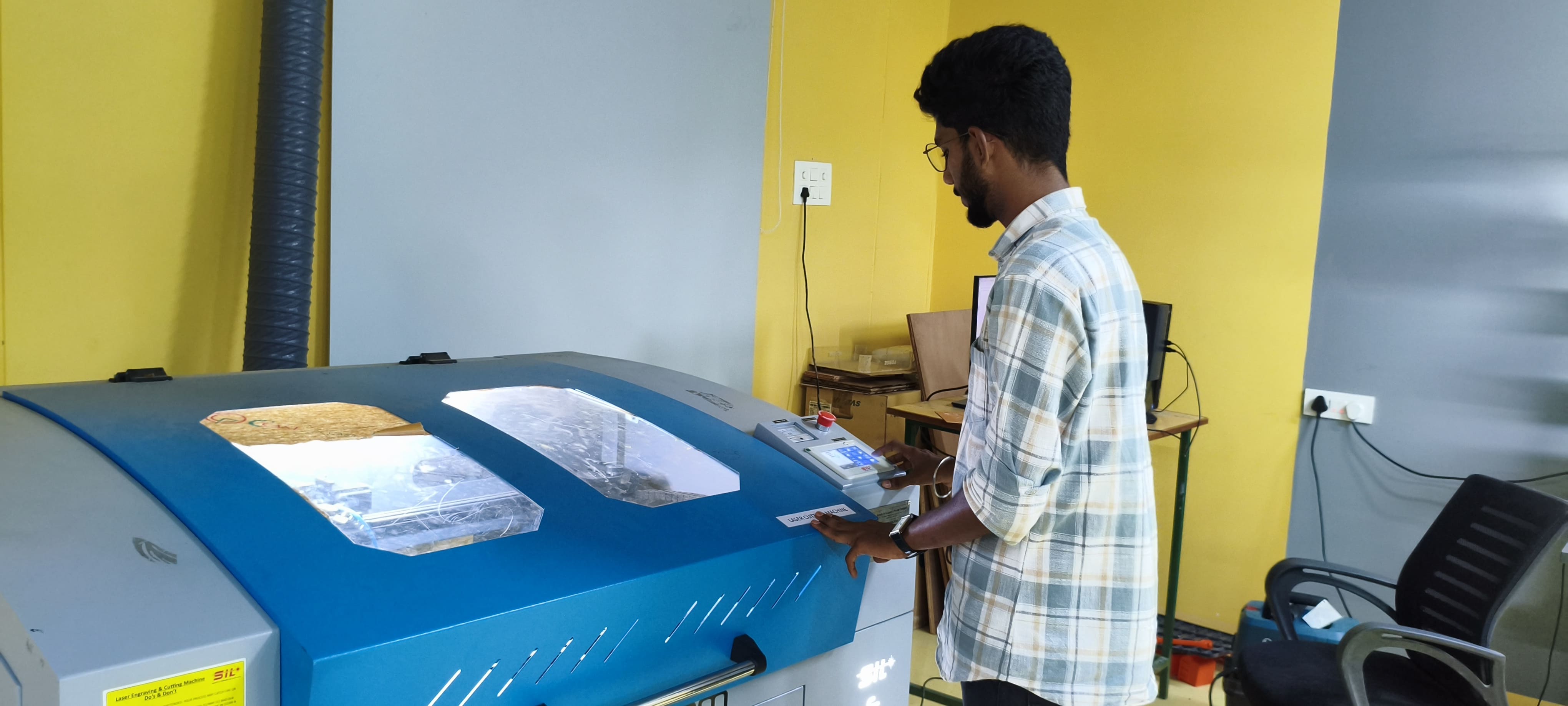
Laser Cutter
A laser cutter is a computer-controlled machine that uses a laser beam to accurately cut or engrave materials. It works by sending a focused laser beam onto the material's surface, melting, burning, or vaporizing it, leaving a clean and exact cut. Laser cutters are flexible instruments that are widely utilized in many industries, including manufacturing, creating, and prototyping. They can cut through a variety of materials, including wood, acrylic, plastic, fabric, and metal, depending on the laser's power and the material's suitability. Laser cutting is valued for its precision, speed, and ability to make complicated shapes, making it a popular choice for elaborate patterns, prototypes, and bespoke items.
At our Trichy Fablab, we are having a C02 Laser Cutter, so we have did a trail and experimenting on the same.
Outcomes
Group assignment:
lab's safety training
Characterize the lasercutter's focus, power, speed, rate, kerf, joint clearance and types.
Document the work to the group work page and reflect on your individual page what you learned.
Individual assignments:
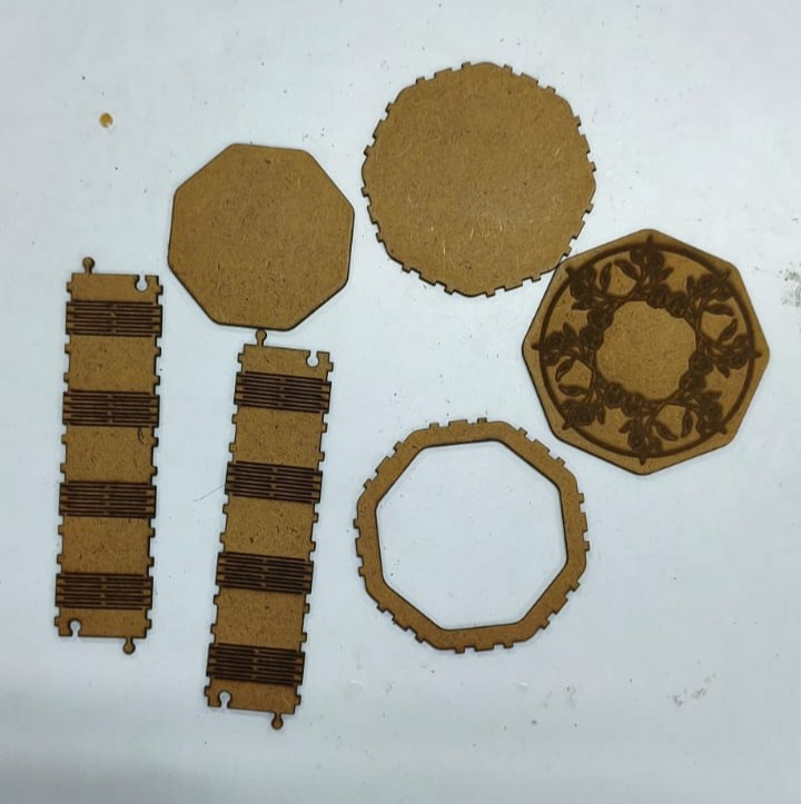
Design, lasercut, and document a parametric construction kit, accounting for the lasercutter kerf, which can be assembled in multiple ways.
Cut something on the vinyl cutter.
reference links


C02 Laser Cutting Device
A CO2 laser engraving and cutting machine is a multipurpose device that uses a powerful laser beam to cut and engrave a variety of materials. The type of laser it utilizes, which produces the laser beam by exciting carbon dioxide gas, is indicated by the "CO2" in the name. This state-of-the-art technique produces a concentrated and potent infrared light beam by using a sealed carbon dioxide gas combination as its laser medium. The CO2 laser cutter is especially good at accurately cutting through materials like leather, wood, acrylic, and some metals, leaving detailed patterns and clean edges. It works well because it can melt or evaporate the material in its path, which makes it appropriate for a variety of uses, including. Its efficiency stems from its capacity to melt or evaporate the material in its path, which makes it appropriate for a variety of uses, including industrial manufacturing procedures and the creation of complex designs. The machine is transforming the way materials are molded and modified thanks to its user-friendly interface and computer-controlled precision, which make it an essential tool for both professionals and enthusiasts.
Click For Group AssignmentIndividual Assignment
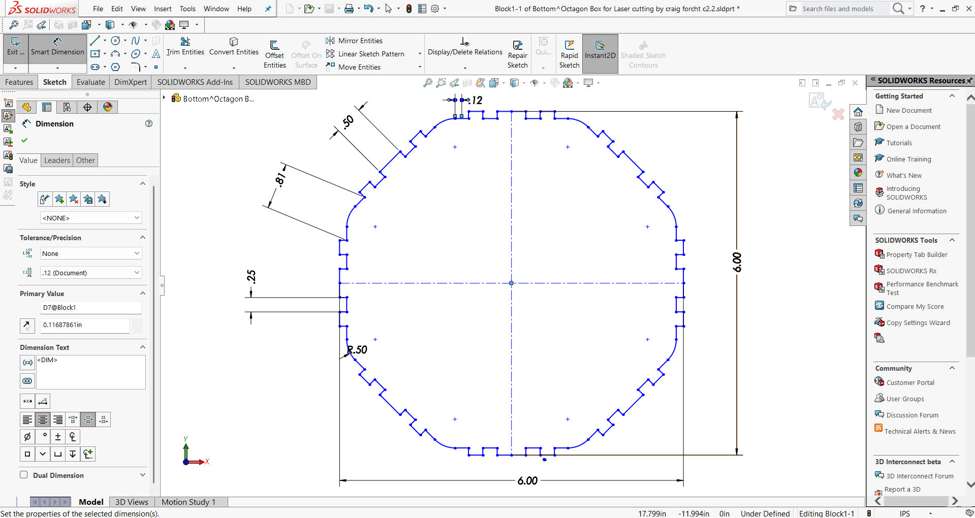
Parametric Designing in Solidworks:
A key component of computer-aided design (CAD) software, parametric design provides a robust toolkit that greatly increases productivity by doing away with the need for manual redesign when changing design dimensions. Design engineers may now create relationships between different attributes thanks to this creative method, which guarantees that changes made to one dimension will automatically affect the rest of the design. Essentially, parametric modeling gives designers the ability to specify whole classes of shapes, offering more flexibility than just particular examples.
In laser cutting processes, where accuracy is crucial, the value of parametric modeling is especially clear. The significance of parametric modeling is shown by the need to modify design elements like slots for press fitting in order to address the kerf in laser cutting. Slot dimensions depend on kerf and material thickness, which can vary depending on a number of variables, including material type, speed, power settings, and more. The designer can dynamically relate the slot width to material thickness and kerf using parametric modeling instead of manually tweaking each dimension.
Learning parametric modeling becomes crucial when it comes to laser cutting, when exact slot dimensions are crucial. This is demonstrated in real-world software applications such as Solid Works.
Parametric Modeling in Solidworks:
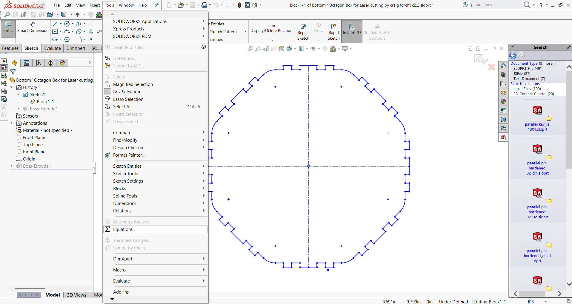
- 1. Initiated the parametric design process by creating a Hexagon shape with slots along its periphery in SolidWorks.
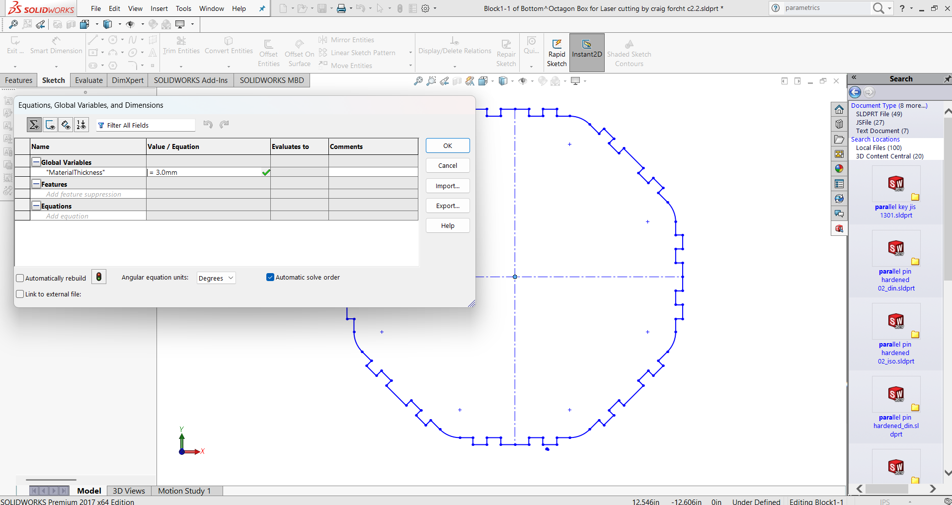
- 2. Go to “Tools” → “Equations”. This opens the Equations, Global Variables, and Dimensions dialog box.
- 3. Define Global Variables. Click “Add” to create global variables:
- MaterialThickness = 3.0
- Kerf = 0.2
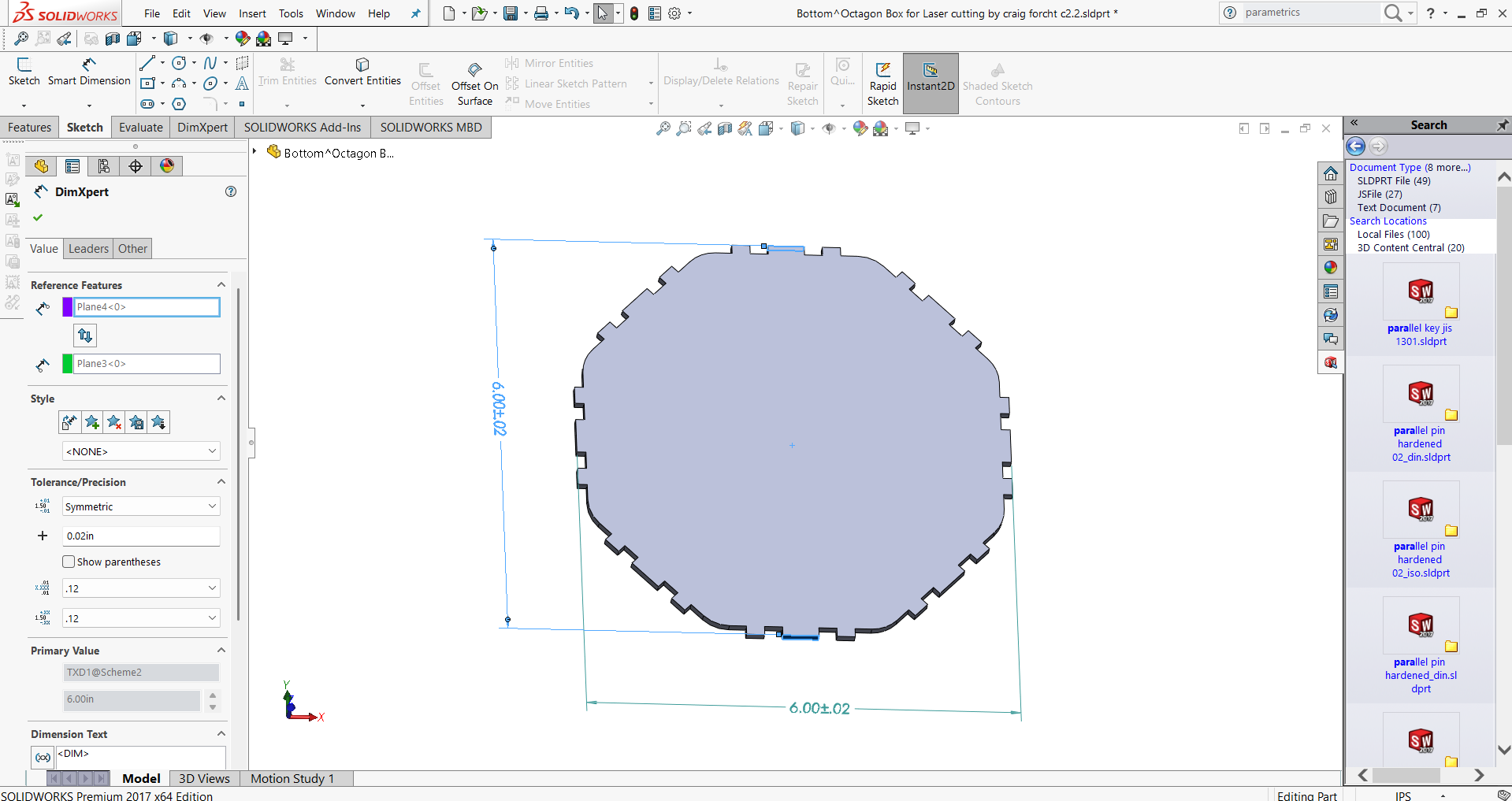
- Identify or create a dimension that controls the slot width.
- In the Value/Equation column for that dimension: = "MaterialThickness" + "Kerf"
- Now the slot width will automatically update whenever MaterialThickness or Kerf changes.
- 3. Modify Parameters Later via “Change Parameters”
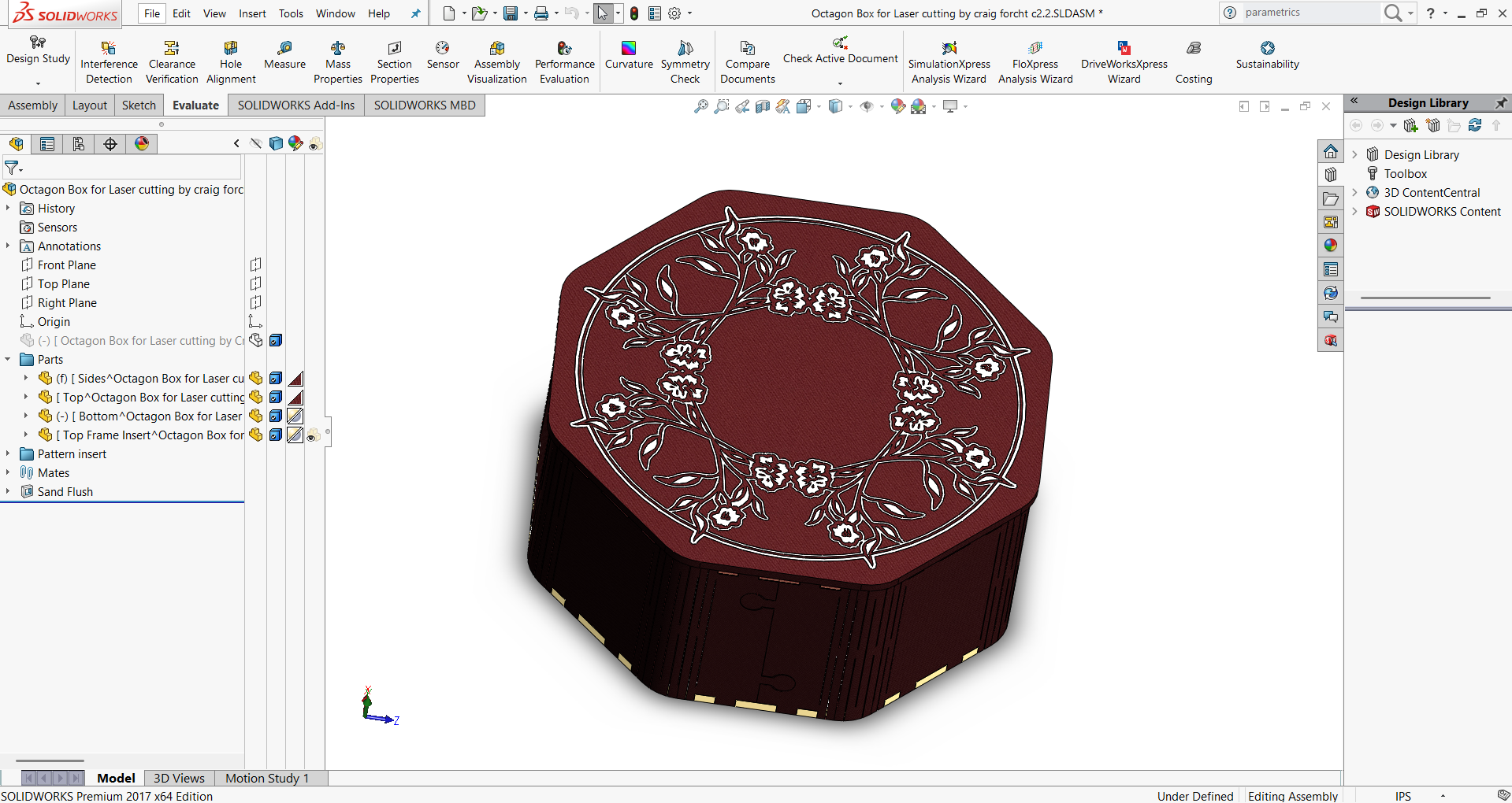
Model Assembly in SolidWorks:
- Step 1: Open a new Assembly, insert the base plate, and fix it at the origin.
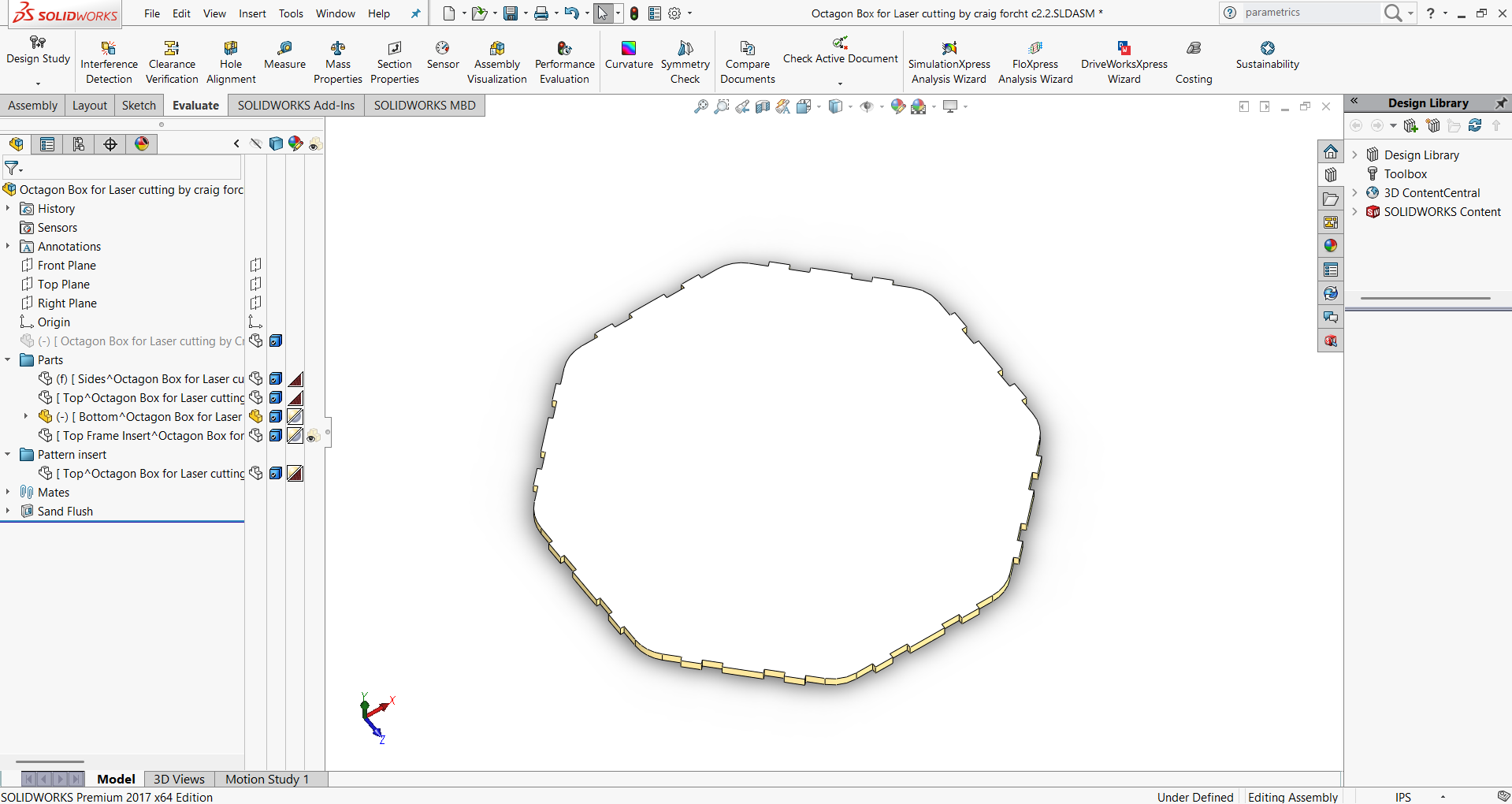
- Step 2: Add the first side wall panel and mate it with the base plate.
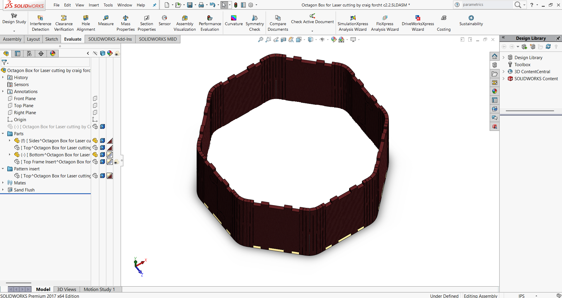
- Step 3: Insert the second side wall panel and align it with the base and the first wall.
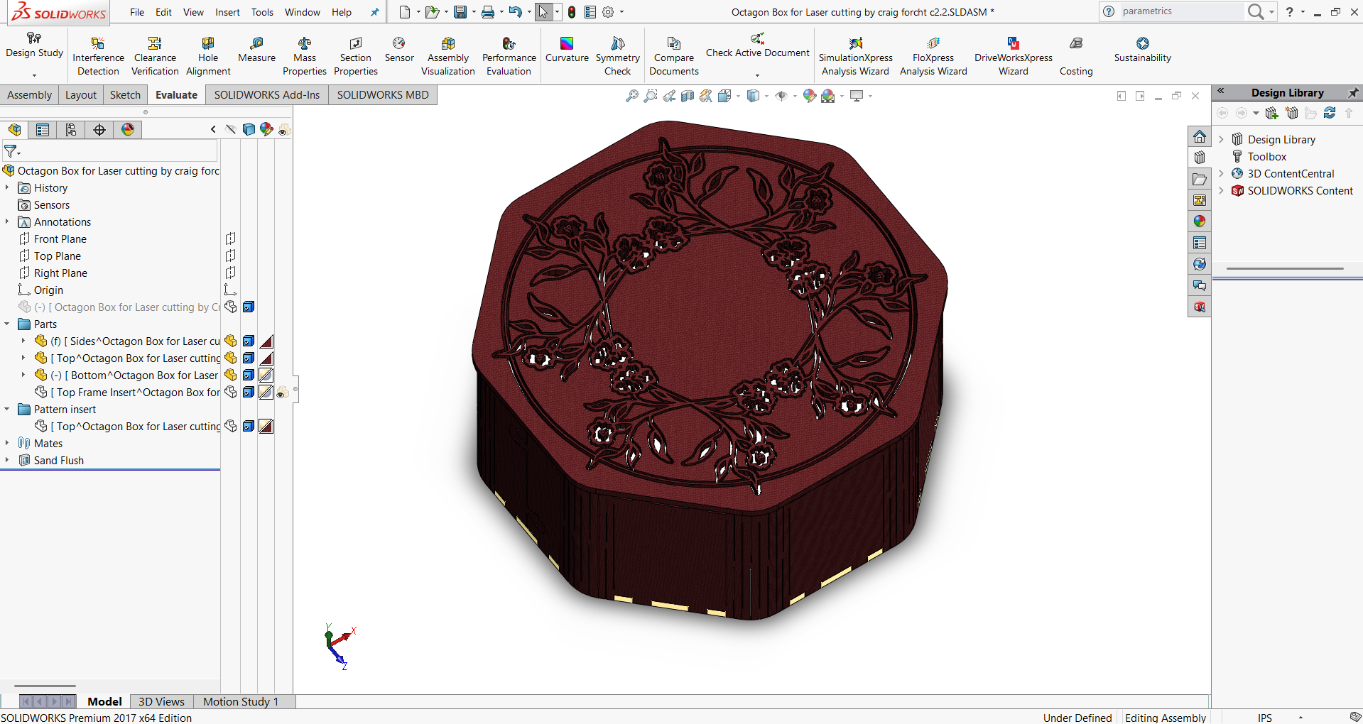
- Step 4: Place the top cover, mate it with the walls, and complete the assembly.
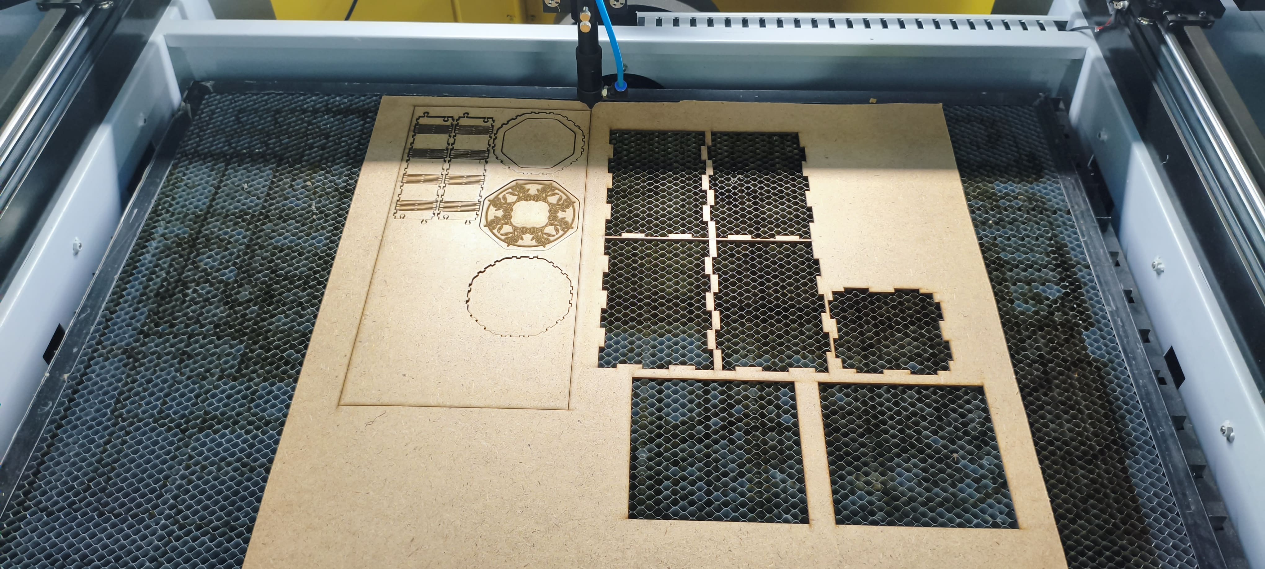
Actual Cutting and Joints
- Step 1: Material Preparation
- The required material sheet was measured and marked according to the design dimensions.
- Proper alignment was ensured before placing it on the cutting machine.
- Step 2: Machine Cutting
- The cutting machine was set up with the correct tool and cutting parameters.
- The design was loaded, and the machine carefully cut the parts from the sheet.
- Step 3: After Cutting
- The cut pieces were removed from the machine bed.
- Each part was inspected to confirm that the edges were clean and accurate to the design.
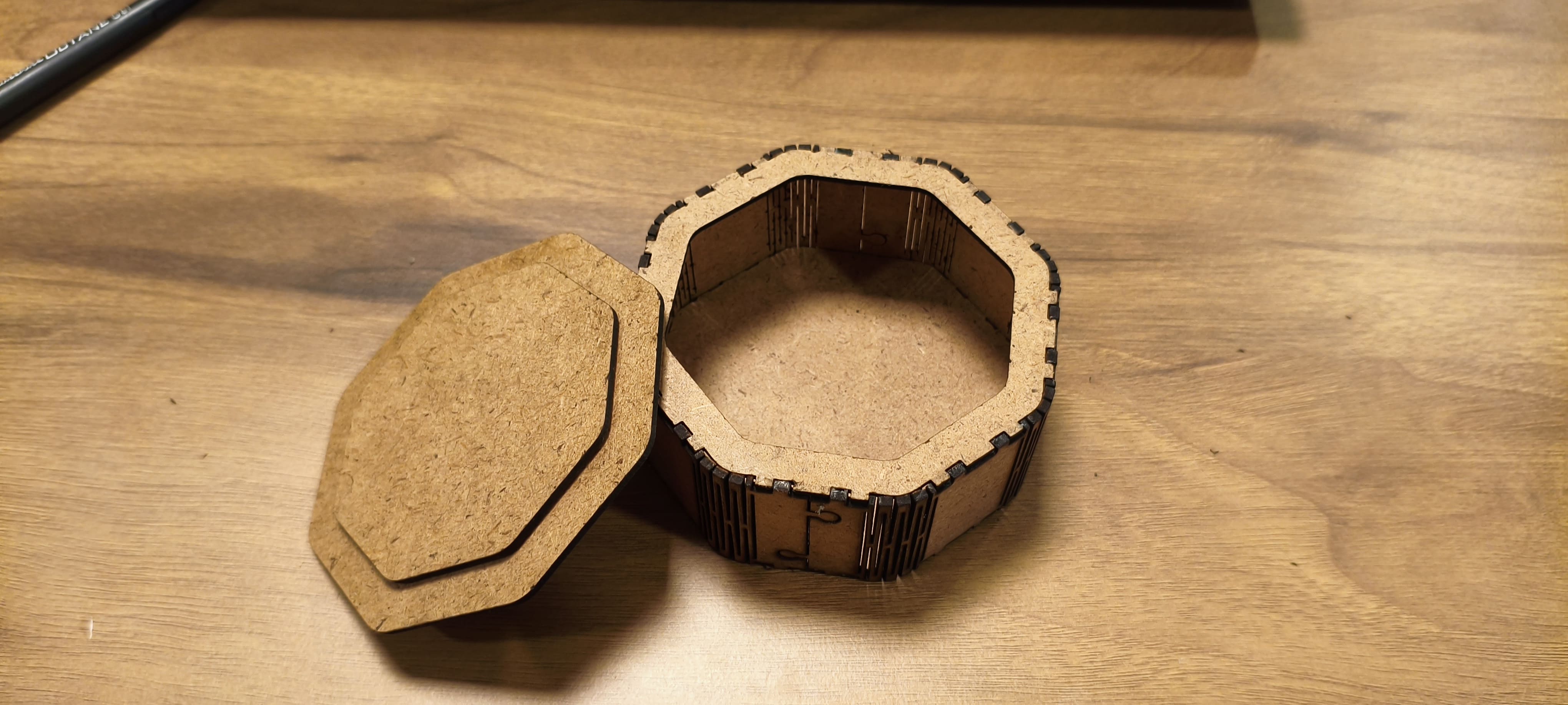
- Step 4: Fitting and Notches
- The individual parts were tested for fitting by aligning the notches and joints.
- Minor adjustments were made to ensure smooth assembly.
- Step 5: Final Assembly
- All the pieces were joined together step by step to form the complete structure.
- Extra care was taken to maintain alignment and strength of the joints.
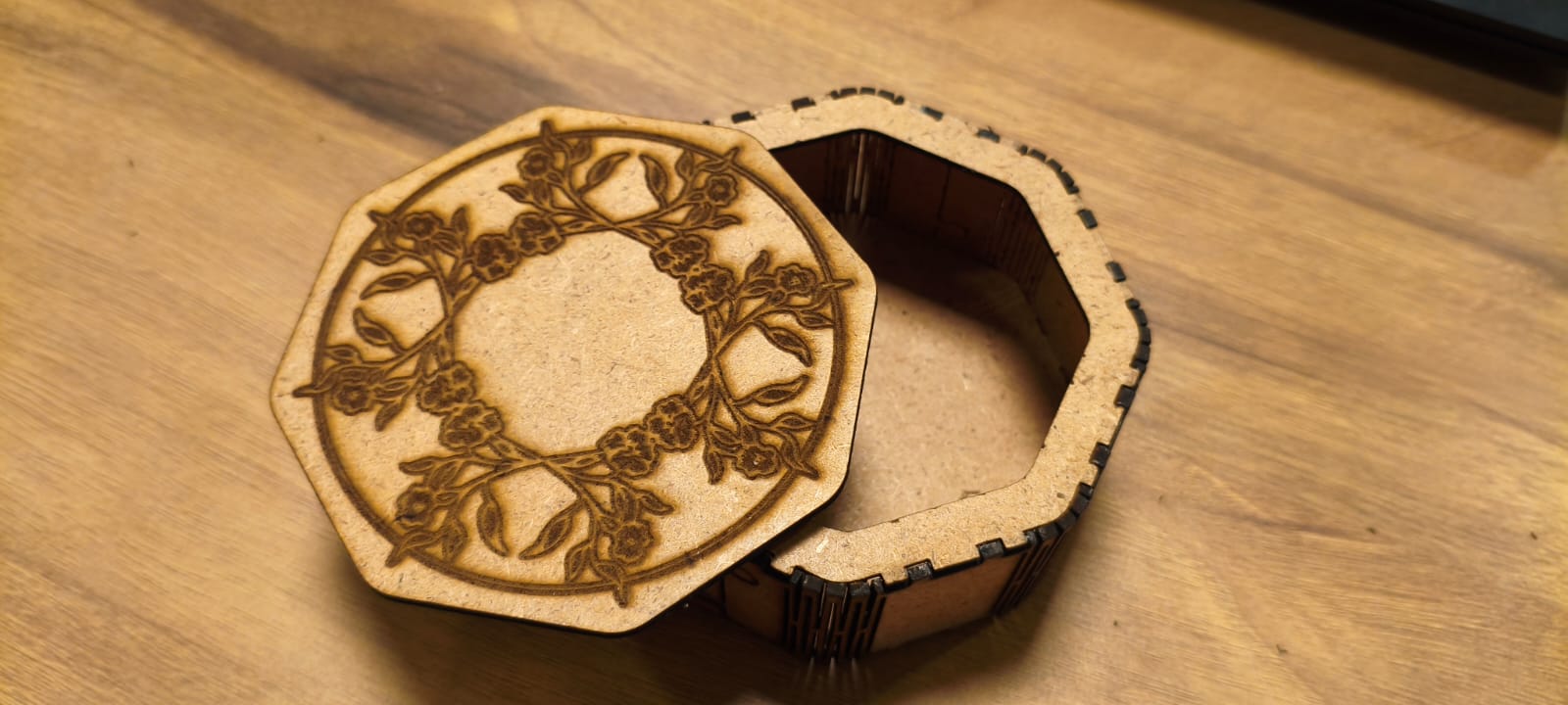
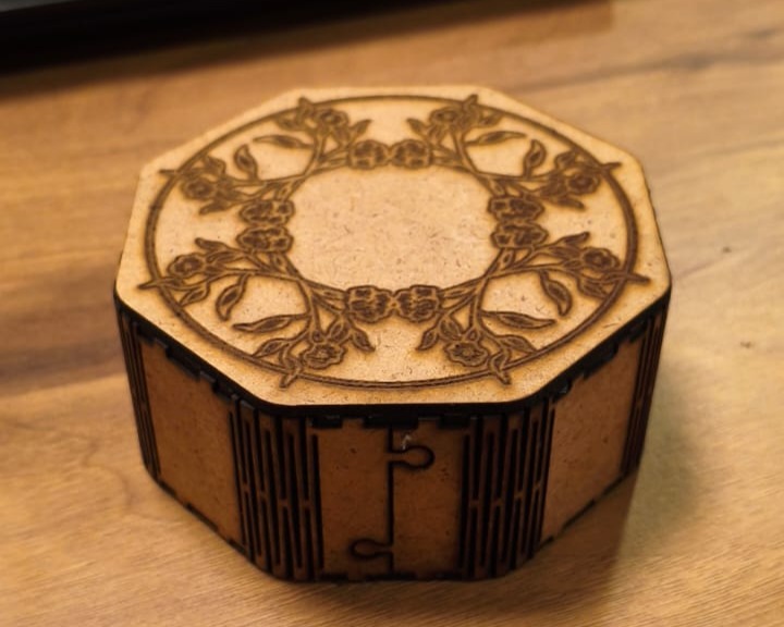
- Step 6: Finished Output
- The fully assembled structure was reviewed for accuracy.
- The final output showed proper fitting, smooth edges, and a neat finish.

Video:
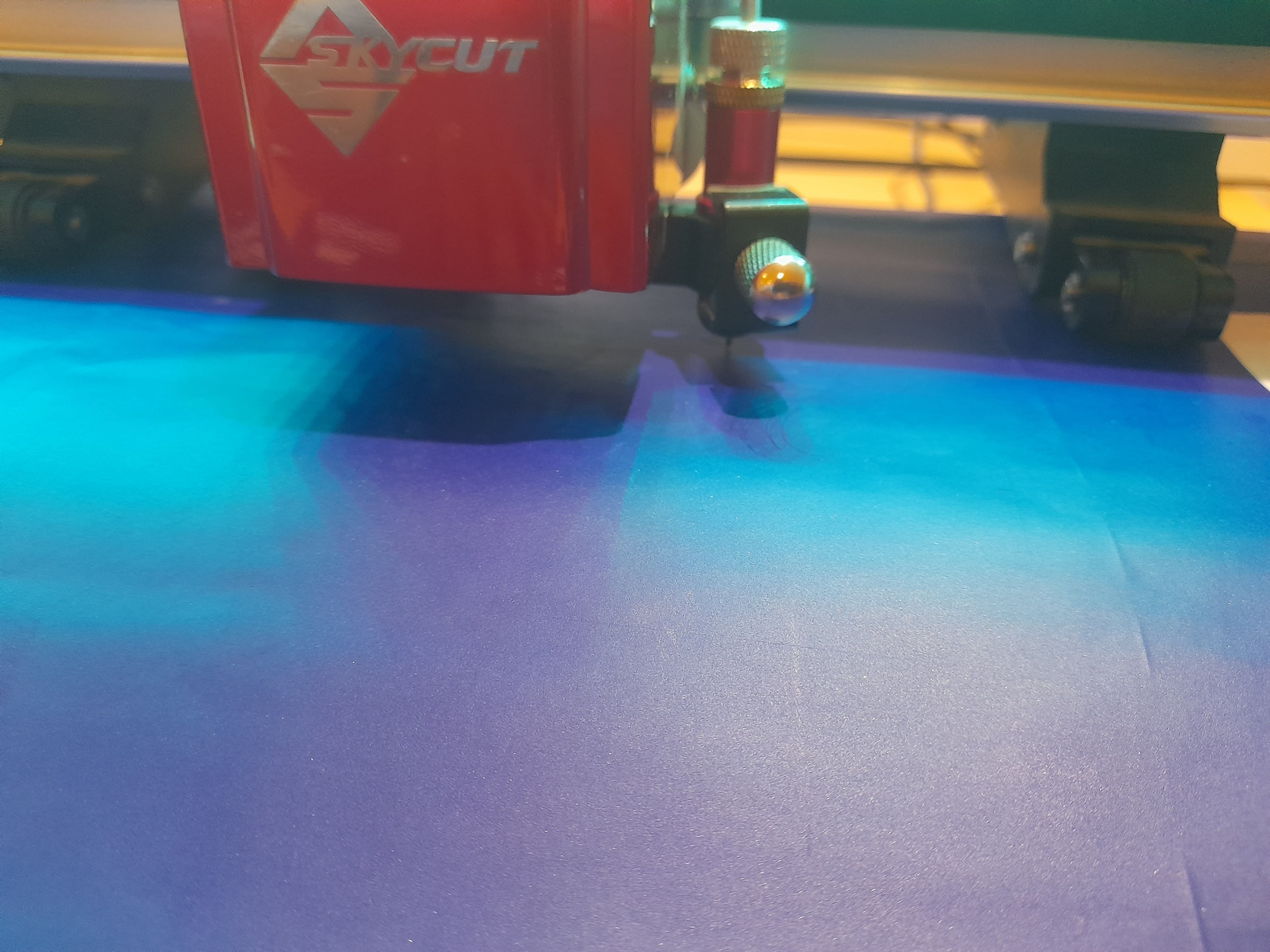
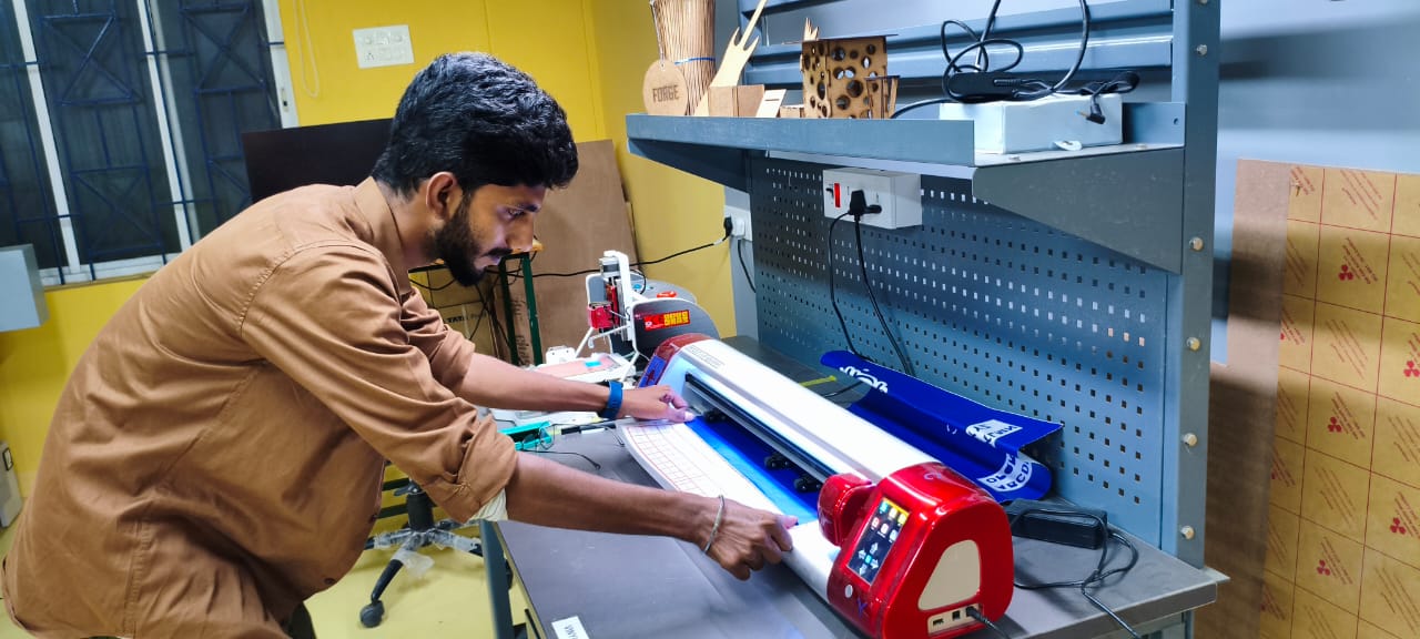
Vinyl Cutter
An excellent entry-level tool for creating signs is a vinyl cutter. It works by cutting computer-generated vector files with letters and patterns straight onto a roll of vinyl. The vinyl, mounted and fed into the cutter, is connected to the computer via a USB or serial cable.
Fablab Trichy Vinyl Cutter Deatils
Skycut C24(720mm) vinyl Cutting plotter
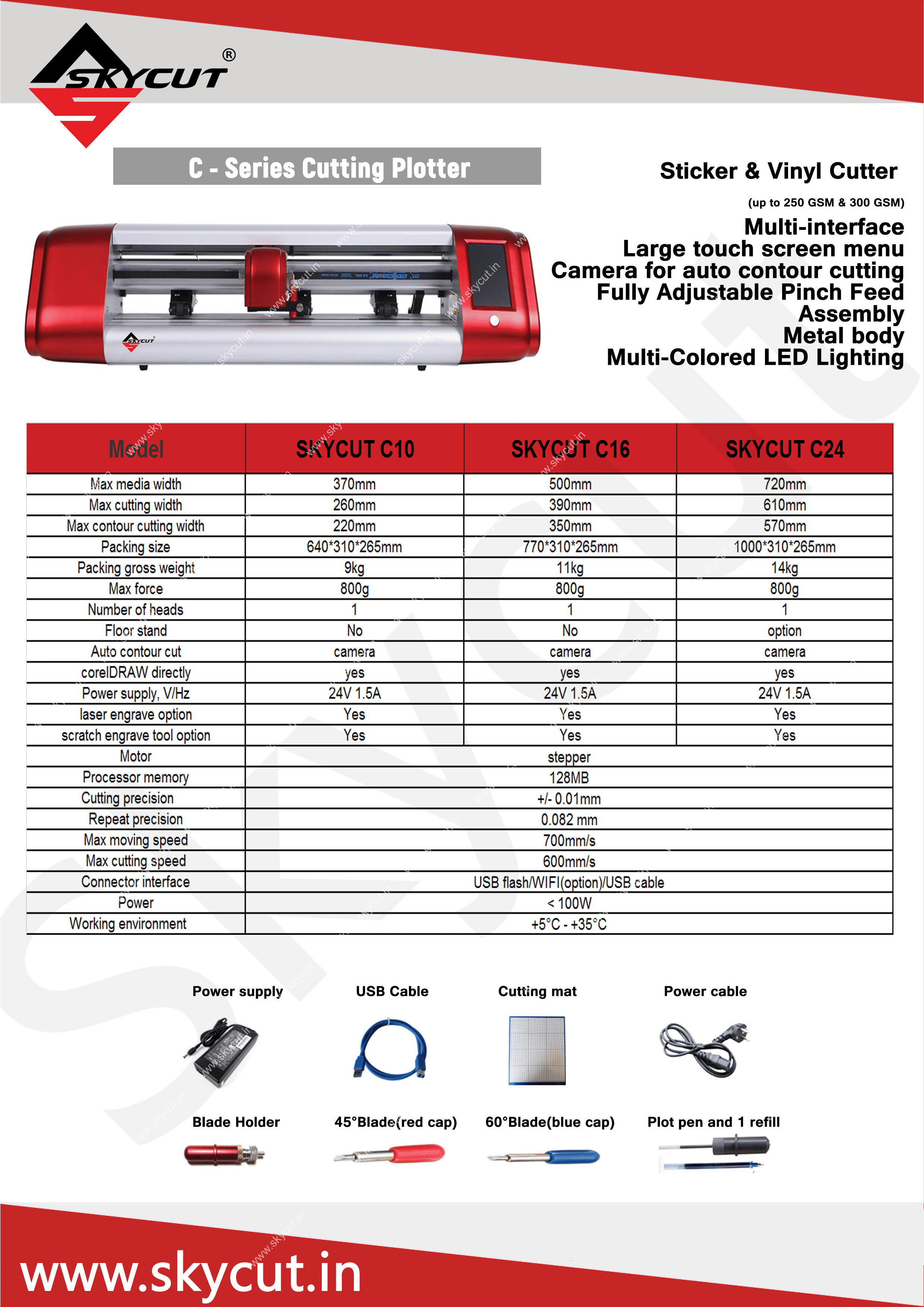
To know more about the Skycut series visit
Skycut C24(720mm) vinyl Cutting plotterVinyl Cutter Assessories
There are several necessary accessories available for the Graphtec Cutting Plotter. The main component is the cutting blade, which is used to cut a variety of materials.
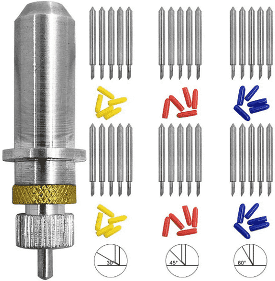
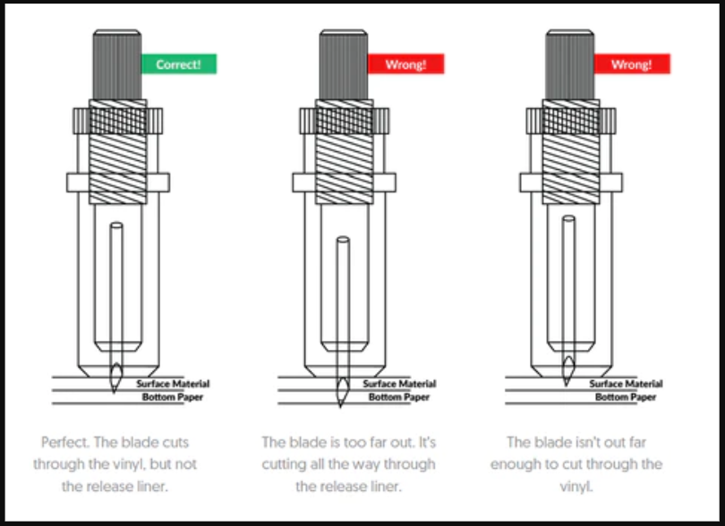
I have observed and studied about different Blade Angles there use and blade settings.
Creating a Design and Cutting of Vinyl Plotter
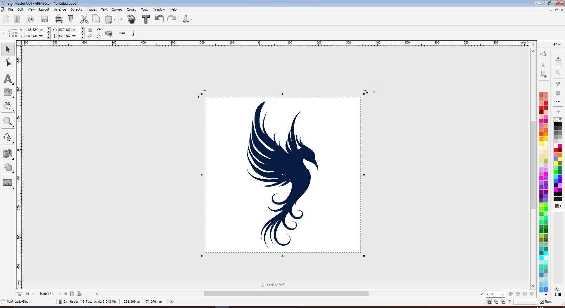
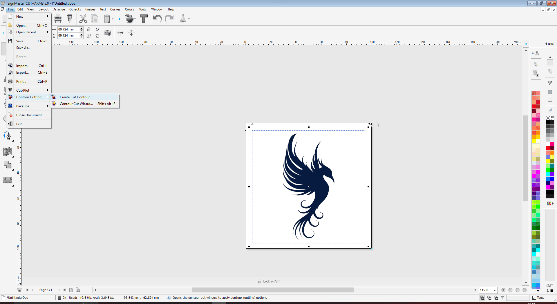
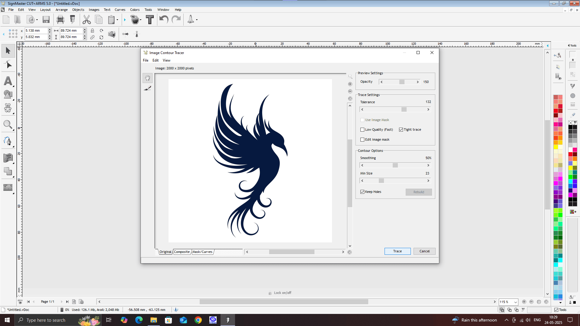
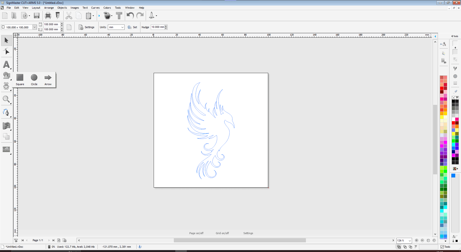
Exporting the design file into DXF format
We require the desired file extension in order to import any file into the plotter machine's cutting program. The file has been exported to DXF format.
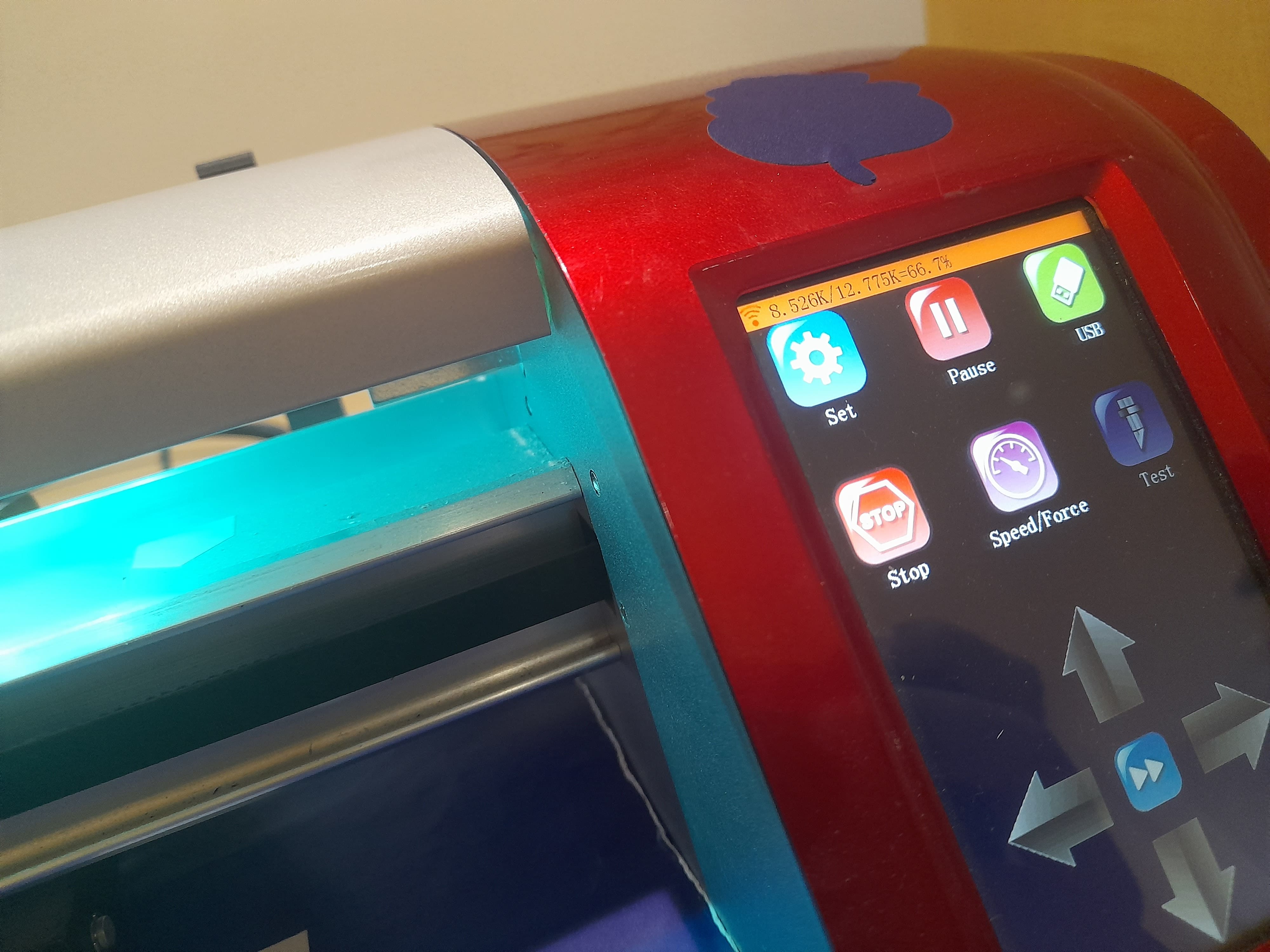
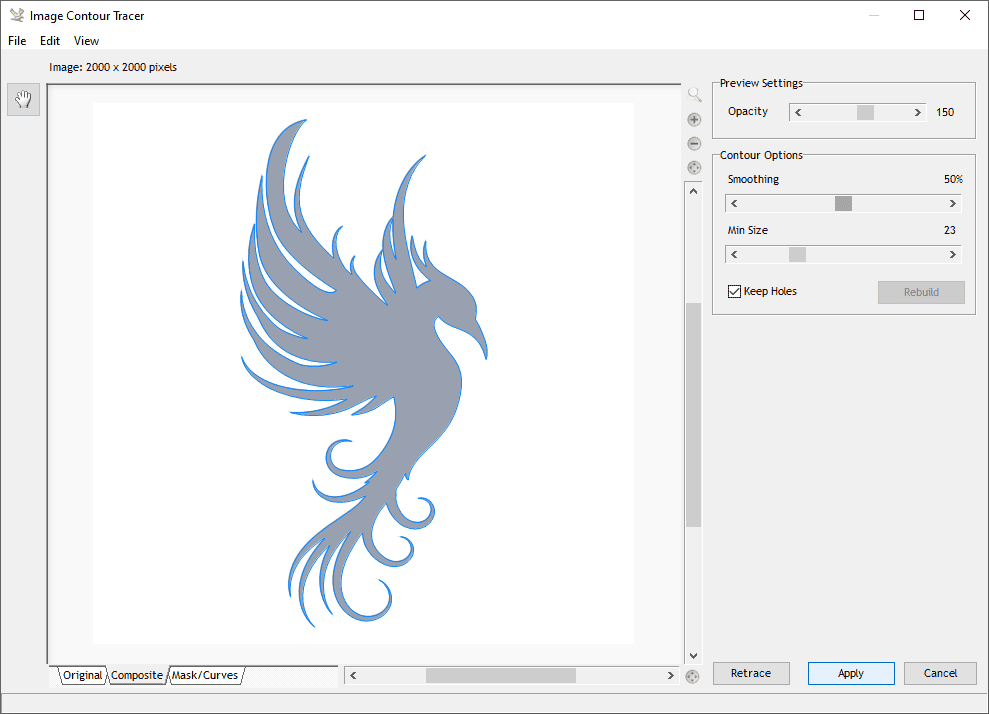
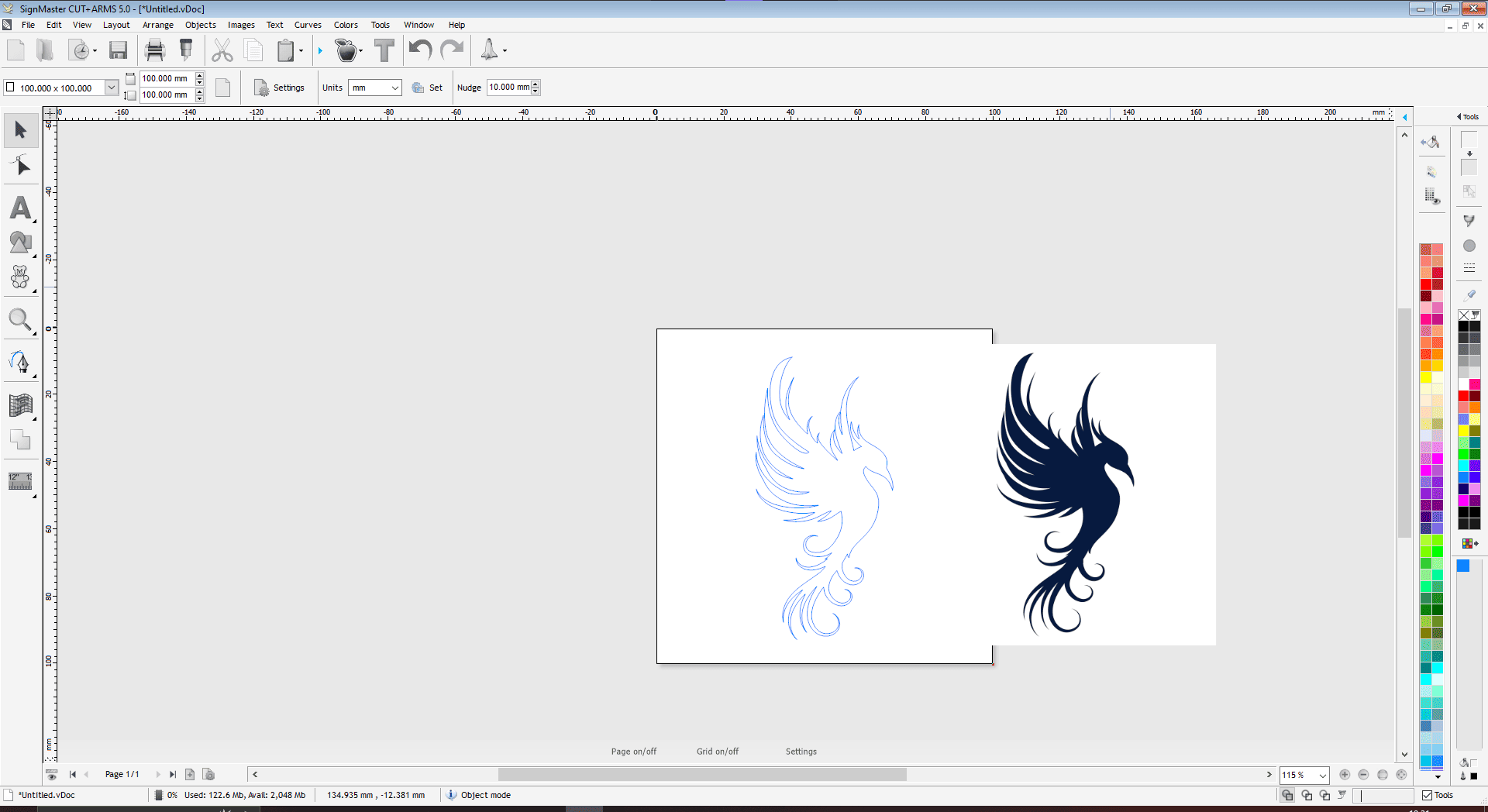
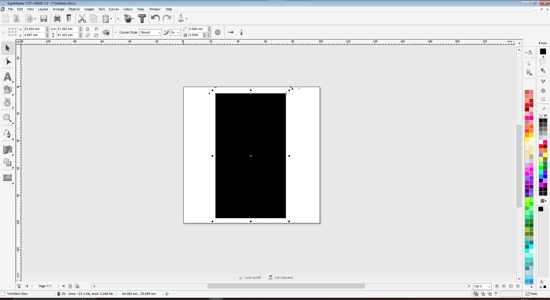
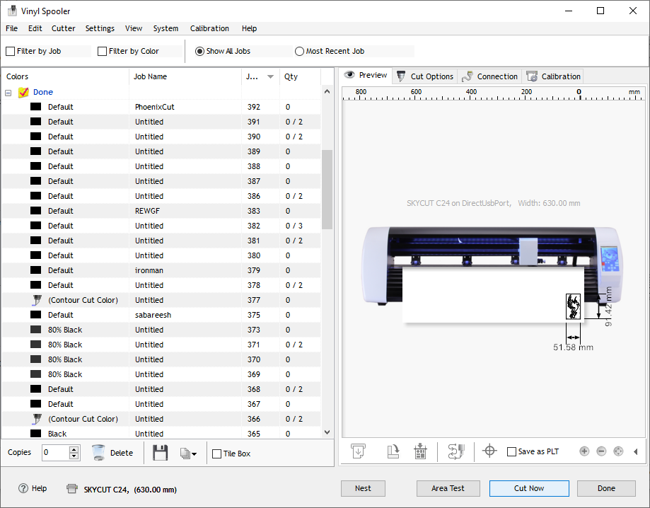
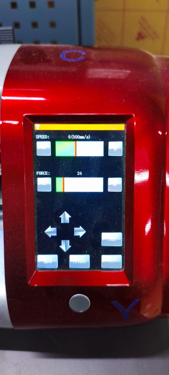
Cutting Software
This machine supports Multiple Studio software for sending cutting file to Plotter Machine
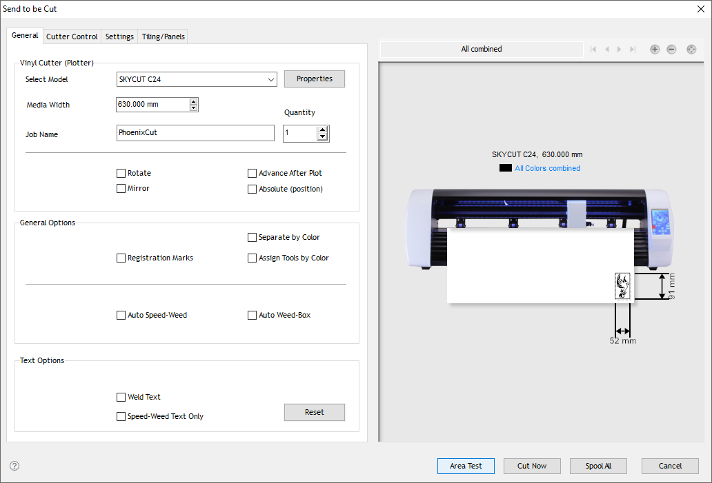
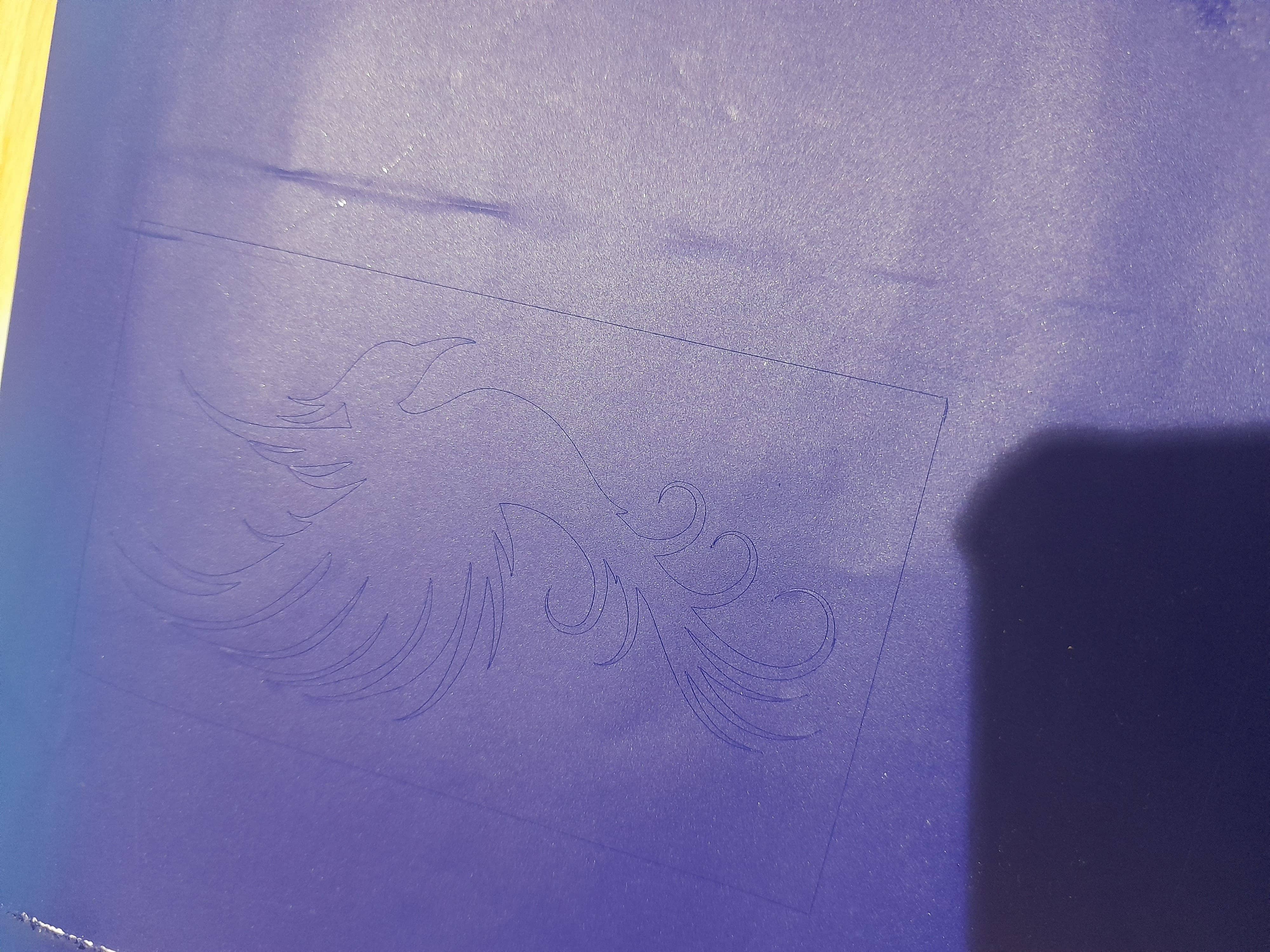
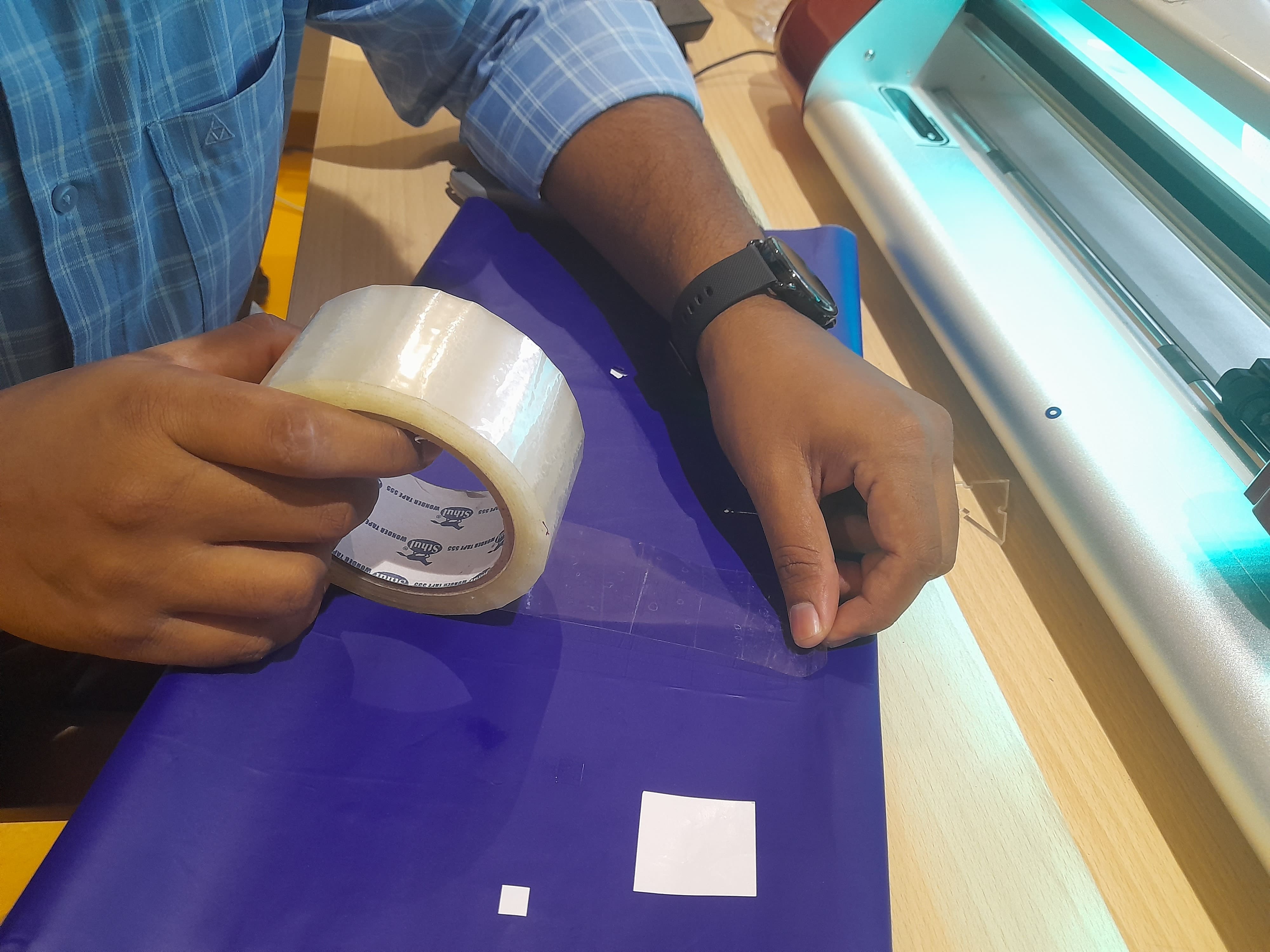
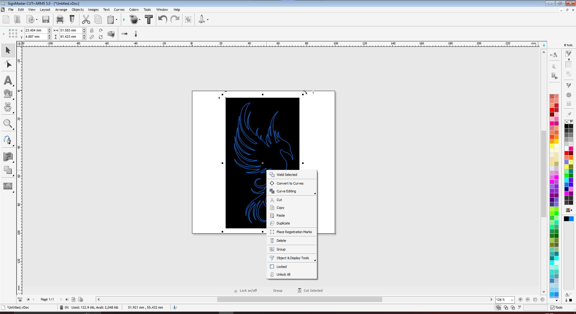
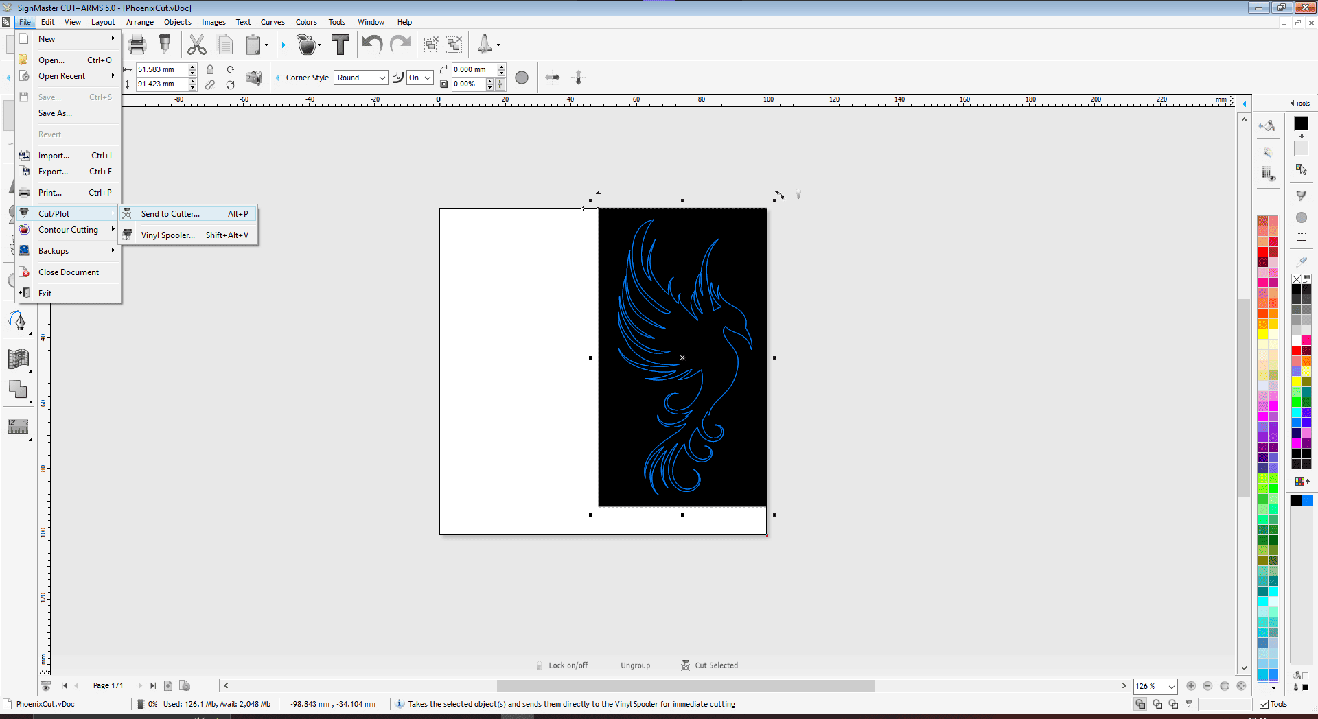
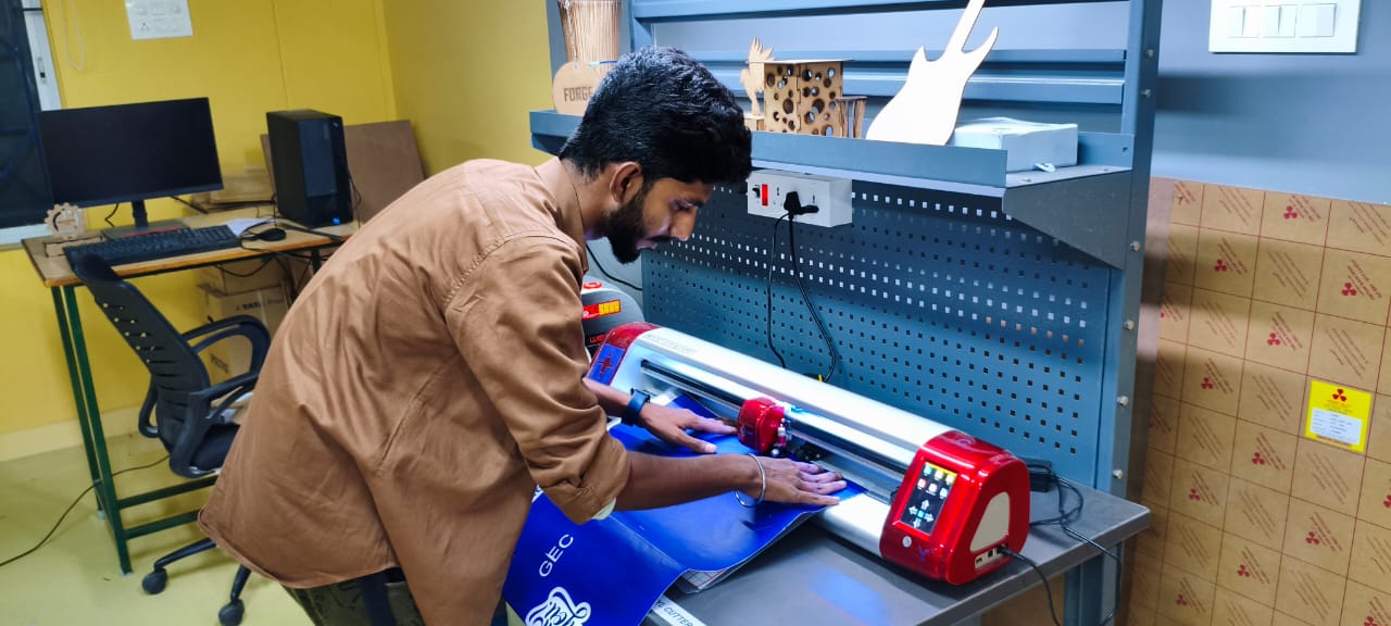
Cutting the design on Vinyl Paper
After the software is loaded with the cutting file, lets start the machine to load the material and and proceed with cutting.
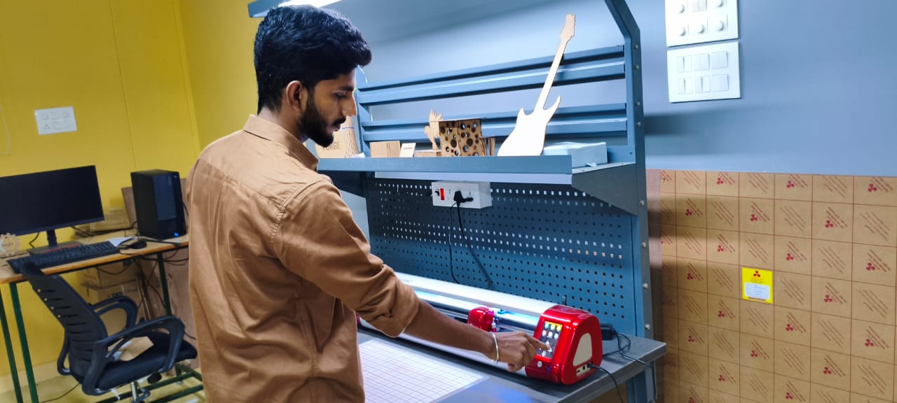
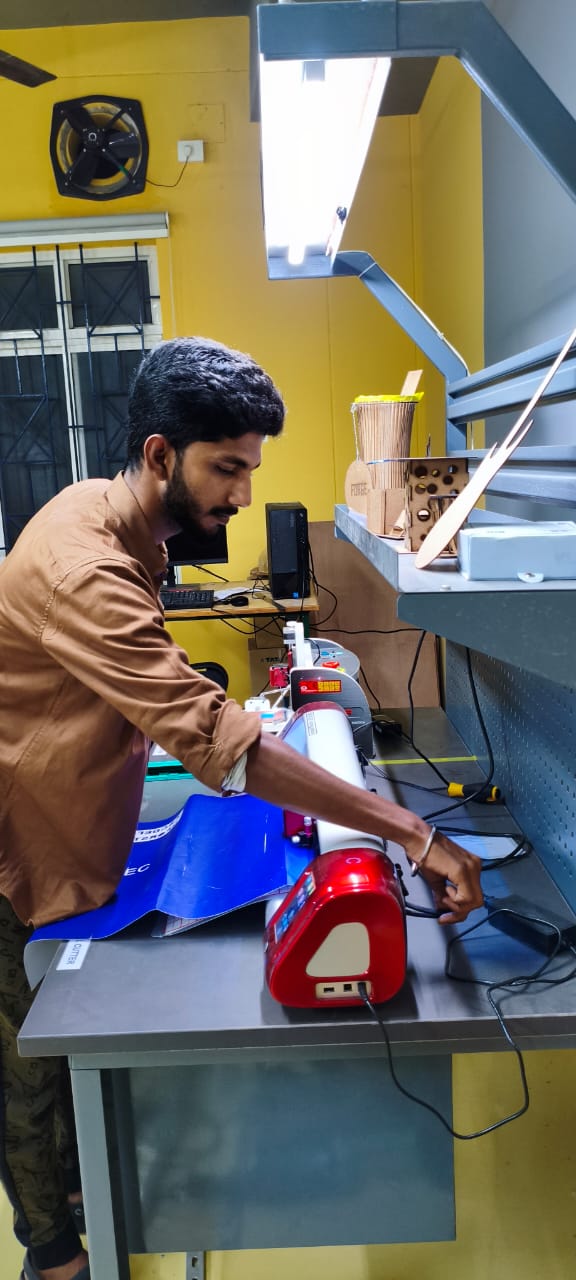
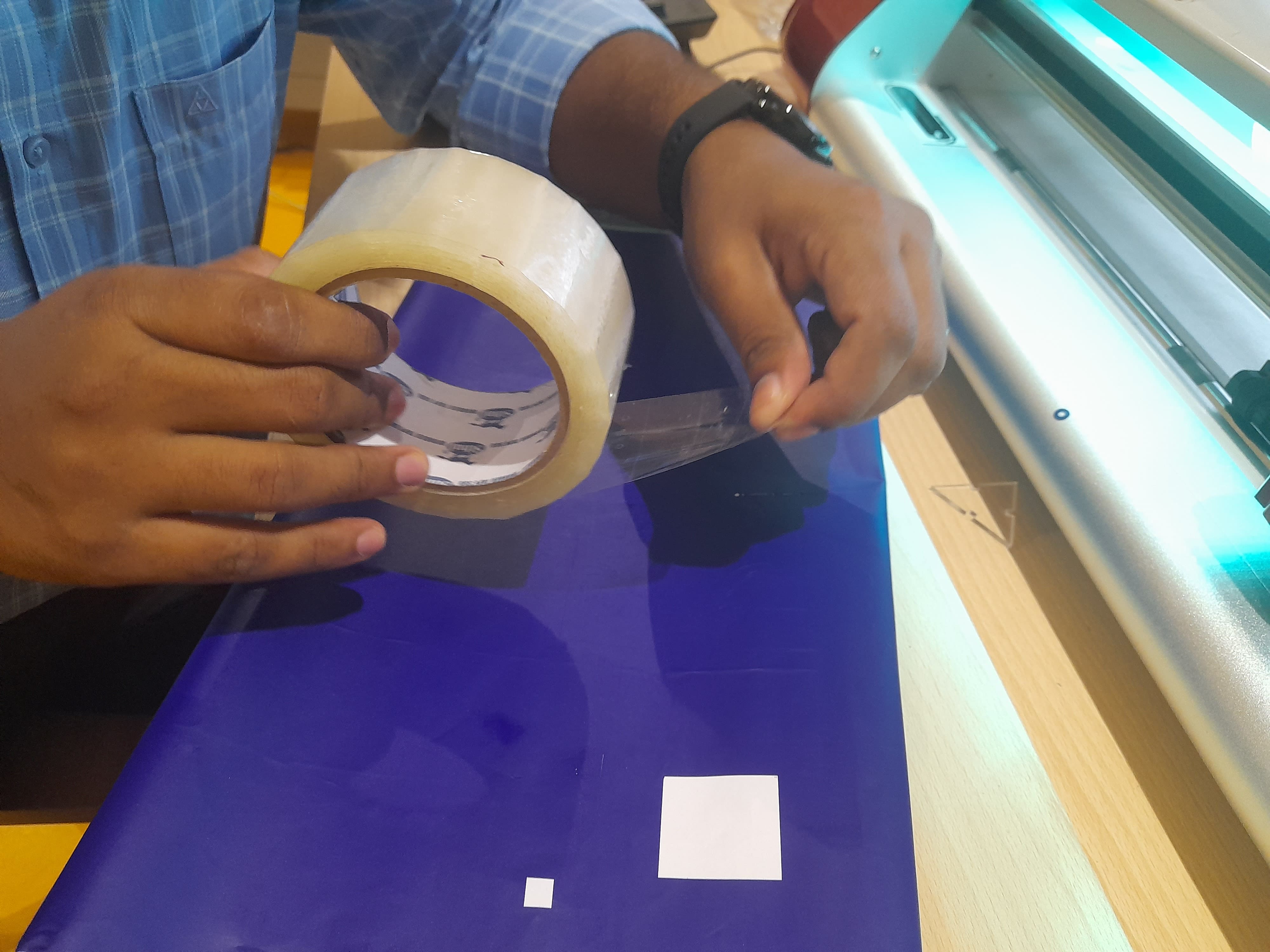
Load the paper facing the colour vinyl paper on the top and the peel off white paper at bottom

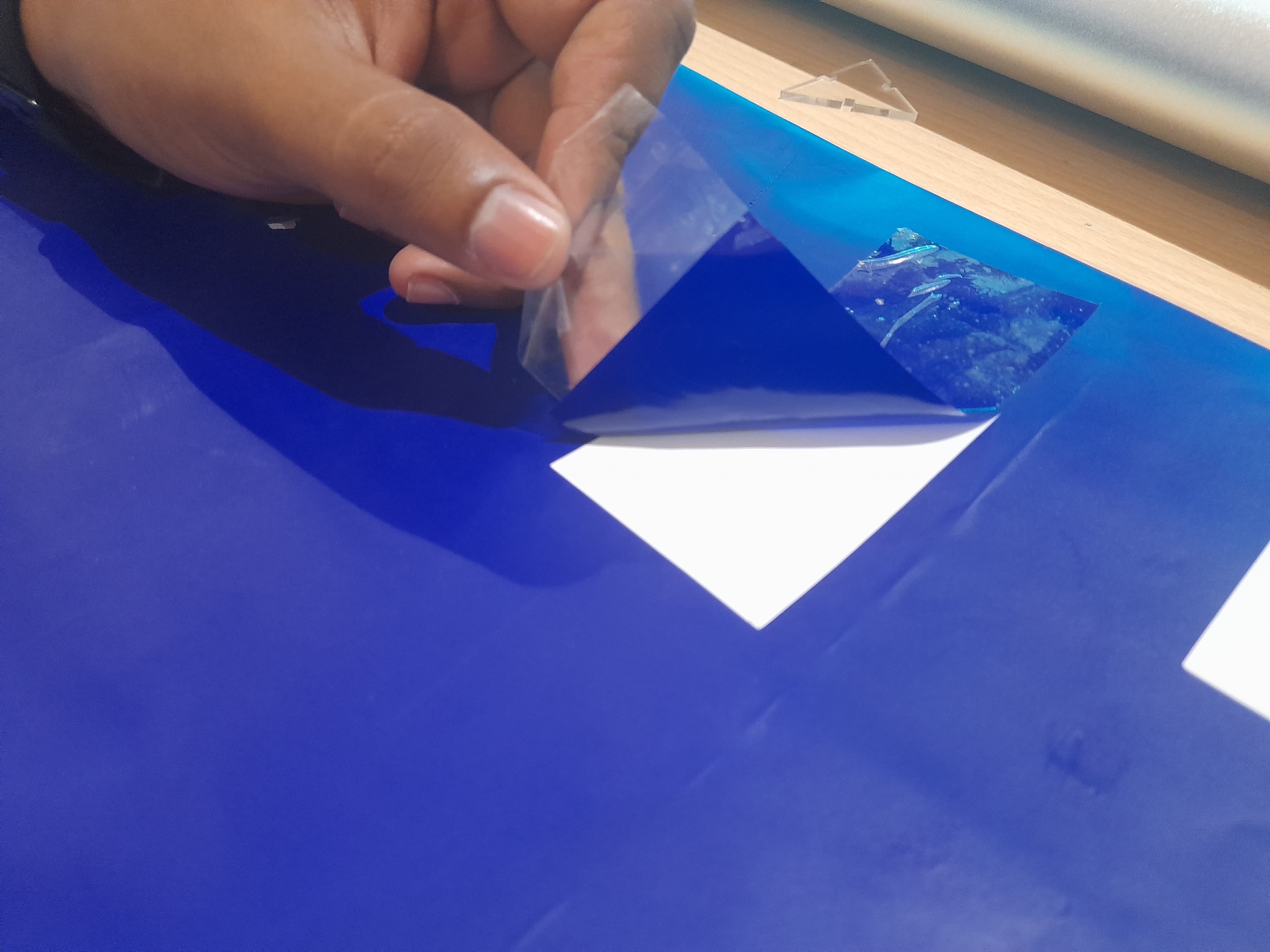
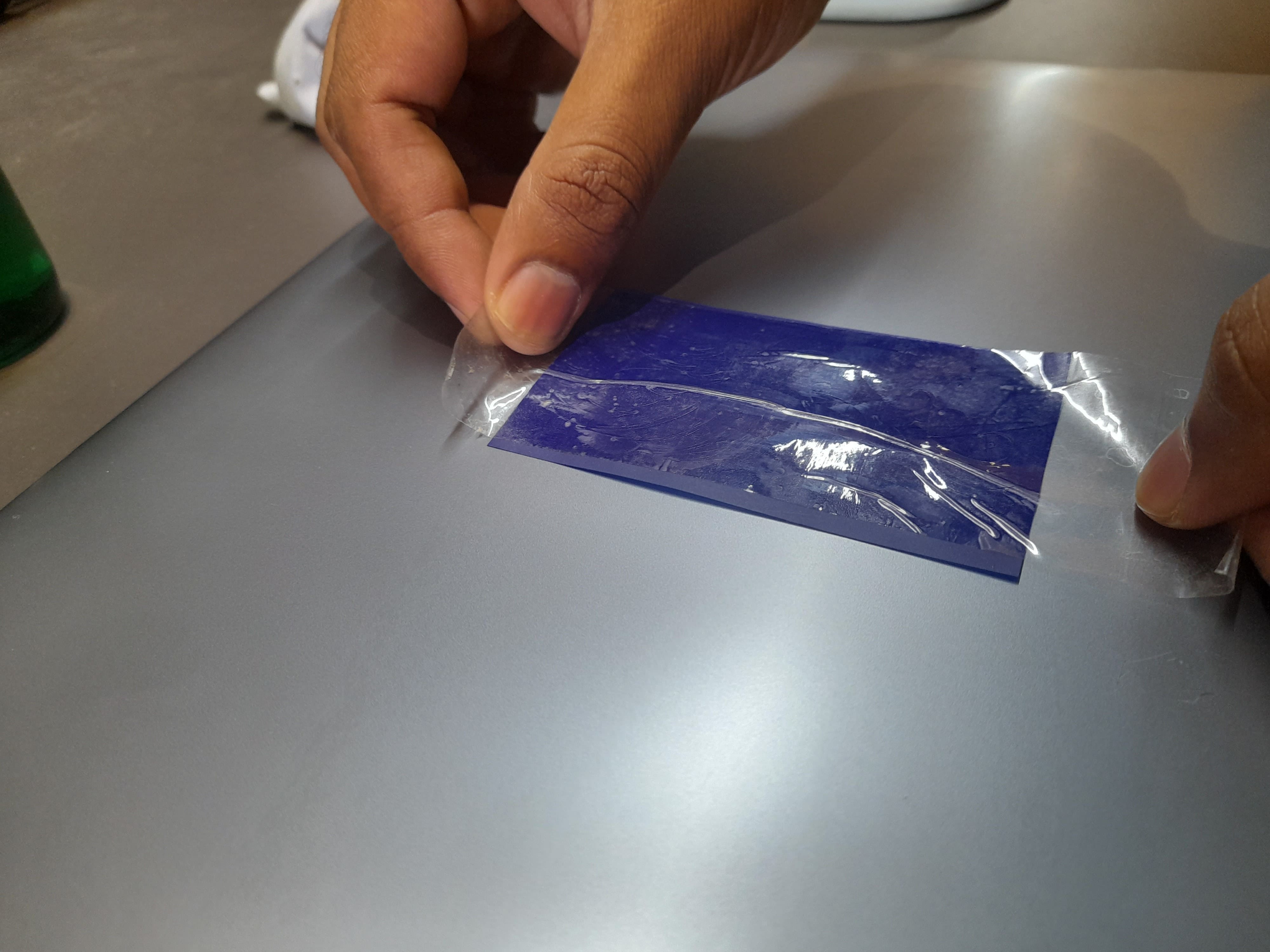
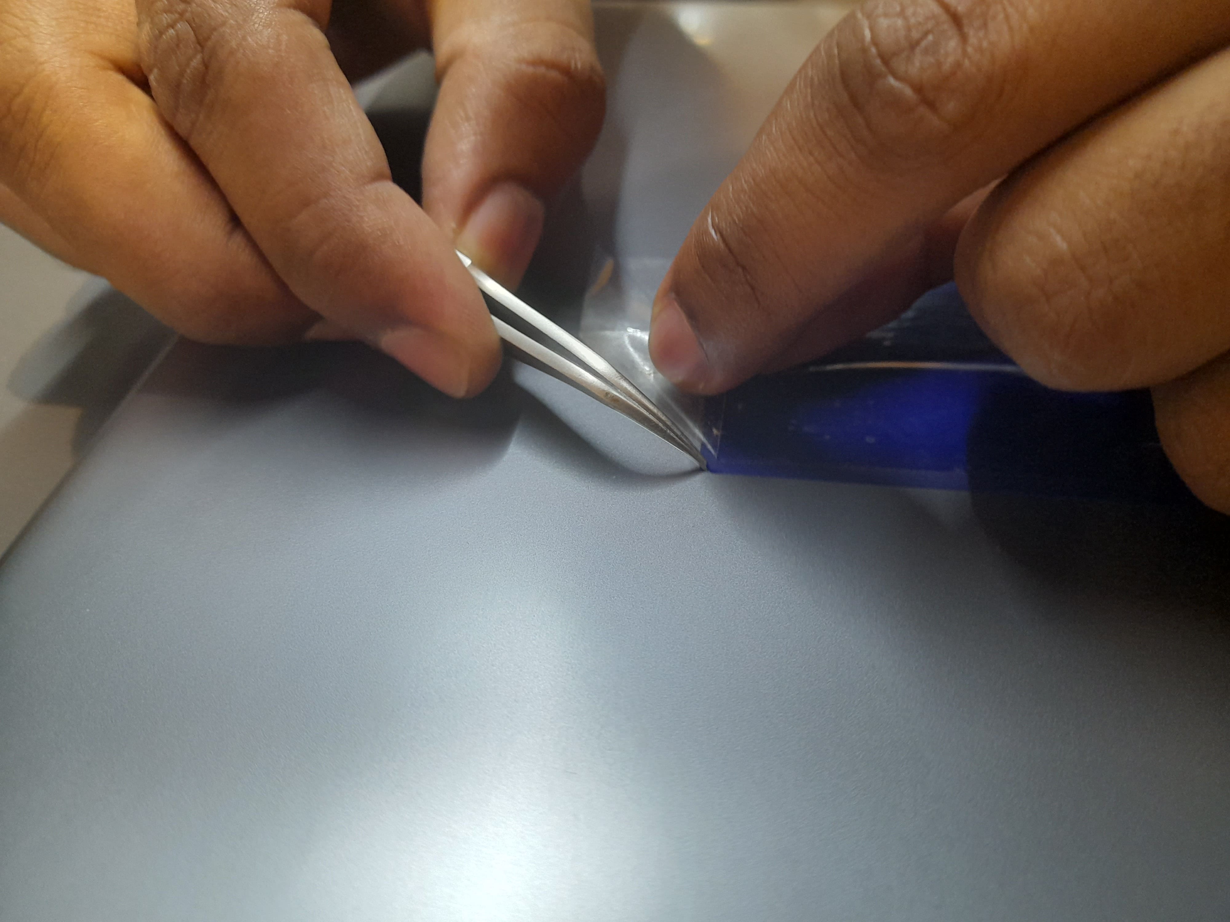
Finished Output