Electronics design
Overview of week 6
Group Assignment
- Use the test equipment in your lab to observe the operation of a microcontroller circuit board
Individual Assignment
- Use an EDA tool to design a development board that uses parts from the inventory to interact and communicate with an embedded microcontroller
- Try another design workflow
- Simulate your design
- Design a case around your design
Individual Assignment :
Electronic components
Passive Components
1.Resistor
Resistor is a passive electrical component that limits or regulates the flow of electric current in a circuit. It is measured in ohms (Ω) and follows Ohm’s Law: V = IR. Resistors are used for voltage division, current limiting, and signal conditioning. They come in various types, such as fixed, variable, and surface-mount. Common materials include carbon, metal film, and wire-wound. Color-coded bands indicate their resistance value. They dissipate electrical energy as heat. Resistors are essential in electronic circuits for stable and controlled operation.

2.Capacitor
Capacitor is a passive electronic component that stores and releases electrical energy. It consists of two conductive plates separated by an insulating material called a dielectric. Capacitors are measured in farads (F) and are used for energy storage, filtering, and signal coupling. Common types include ceramic, electrolytic, and film capacitors. They block DC while allowing AC signals to pass. The capacitance value depends on plate area, distance, and dielectric material. Capacitors are widely used in power supplies, timing circuits, and electronic devices.

3.Inductor
An inductor is a passive electronic component that stores energy in a magnetic field when electric current flows through it. It consists of a coil of wire wound around a core, which can be air, iron, or ferrite. Inductance is measured in henries (H). Inductors resist changes in current, making them essential in filtering, energy storage, and tuning circuits. They are commonly used in power supplies, transformers, and radio-frequency applications. The inductance value depends on the coil’s number of turns, core material, and shape.

Active Components
4.Diode
A diode is a semiconductor device that allows current to flow in one direction while blocking it in the opposite direction. It has two terminals: anode (+) and cathode (-). The most common type is the PN junction diode, which conducts when forward-biased and blocks current when reverse-biased. Diodes are used for rectification, voltage regulation, and signal modulation. Special types include Zener diodes (voltage regulation), LEDs (light emission), and Schottky diodes (fast switching). They are essential in power supplies, communication circuits, and electronic devices.

5.Transistor
A transistor is a semiconductor device used for amplification, switching, and signal modulation. It has three terminals: collector, base, and emitter (for bipolar junction transistors, BJT) or drain, gate, and source (for field-effect transistors, FET). Transistors are classified into NPN and PNP (BJTs) or NMOS and PMOS (FETs). They control current flow using a small input signal. Common applications include amplifiers, digital logic circuits, and power regulation. Transistors revolutionized electronics, replacing vacuum tubes due to their small size, efficiency, and reliability.

Electromechanical Components
6.Switch
A switch is an electrical device used to control the flow of current in a circuit by opening (off) or closing (on) the connection. It comes in various types, including toggle, push-button, rotary, slide, and reed switches. Switches can be mechanical (operated manually) or electronic (such as transistors and relays). They are classified based on poles and throws, like SPST, SPDT, DPST, and DPDT. Common applications include power control, circuit protection, and automation. Switches are essential components in electrical and electronic systems for controlling operations safely and efficiently.

7.Relay
A relay is an electromechanical or solid-state switch that controls high-power circuits using a low-power signal. It consists of a coil, contacts, and a switching mechanism. When the coil is energized, it creates a magnetic field that moves the contacts, opening or closing the circuit. Relays are classified into electromechanical relays (EMR), solid-state relays (SSR), and reed relays. They are used in automation, motor control, protection circuits, and communication systems. Common types include SPST, SPDT, DPST, and DPDT. Relays provide electrical isolation and allow small signals to control large loads efficiently.

8.Transformer
A transformer is an electrical device that transfers AC power between circuits through electromagnetic induction. It consists of a primary coil, secondary coil, and a magnetic core. Transformers operate based on Faraday’s Law of Induction and can step up (increase) or step down (decrease) voltage. They are classified into power, distribution, isolation, and autotransformers. Core materials include iron and ferrite for efficient magnetic flux transfer. Transformers are essential in power transmission, electronic circuits, and industrial applications. They provide electrical isolation and ensure safe voltage levels for various devices.

PCB Designing
PCB (Printed Circuit Board) designing involves creating a layout for electronic circuits on a board to connect components efficiently. It includes schematic design, component placement, routing, and optimization using software like Altium, KiCad, or Eagle. PCBs can be single-layer, double-layer, or multi-layer, depending on complexity. Key considerations include trace width, signal integrity, thermal management, and manufacturability. PCBs replace traditional wiring, making electronic devices compact, reliable, and efficient. They are widely used in consumer electronics, industrial equipment, and robotics.
Why PCB Designing?
PCB (Printed Circuit Board) designing is crucial for building compact, efficient, and reliable electronic circuits. It eliminates the need for bulky wiring by providing a well-organized layout of electrical connections. PCBs ensure mechanical support and proper power distribution to components, reducing short circuits and interference issues.
One of the key advantages of PCB design is its ability to enhance signal integrity and reduce electromagnetic interference (EMI), making circuits more stable. It also improves thermal management, allowing heat dissipation to prevent component damage. PCBs come in single-layer, double-layer, and multi-layer designs, enabling complex circuits to be accommodated in smaller spaces.
With PCB design, manufacturers can achieve mass production with high precision, ensuring consistency and reducing manufacturing costs. It enables the integration of automated assembly and testing, making production faster and more reliable. PCBs are widely used in consumer electronics, industrial automation, medical devices, automotive systems, aerospace, and robotics.
Overall, PCB designing is a fundamental part of modern electronics, allowing engineers to create advanced, high-performance, and durable electronic products.


These are few examples of the challenges faced by electronic engineers. By overcome this issues we will use the softwares in this modern world.
There are several PCB design software options available, ranging from beginner-friendly to professional-grade tools. Here are some popular EDA software tools,
- Fusion 360
- KiCad
- Eagle CAD
- OrCAD
- EasyEDA
- Altium Designer
I used the KiCad software to design the PCB in this week.
KiCad
KiCad is a free, open-source PCB design tool used for schematic capture, PCB layout, and 3D visualization. It supports multi-layer PCBs and provides an extensive component library. The schematic editor helps design circuits, while the PCB layout editor offers advanced routing options. It includes a 3D viewer to visualize board designs before fabrication. KiCad can export Gerber files for manufacturing and supports SPICE simulation. It is cross-platform (Windows, macOS, Linux) and widely used by hobbyists and professionals. With no licensing fees, it is a cost-effective choice for PCB designing.
Open the new file, it will open two work space - Schematic editor and PCB editor, open the schematic editor(ctrl+E)

In the right corner we will see the various options, here are the short keys to work efficiently in this software

After connecting the wires you can check the circuit whether it is correct or not

If anything we did mistakenly then the errors will appear and we will rectify with the help of that

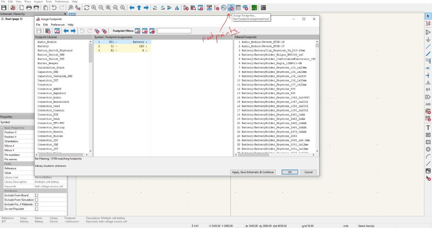
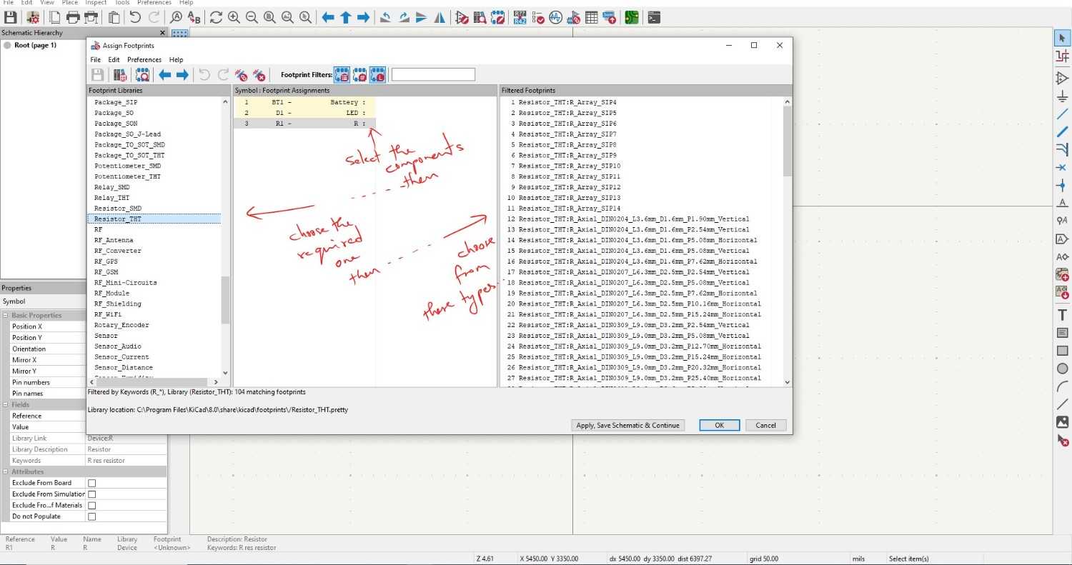
we can see the footprints here, able to select the variety of differnt components


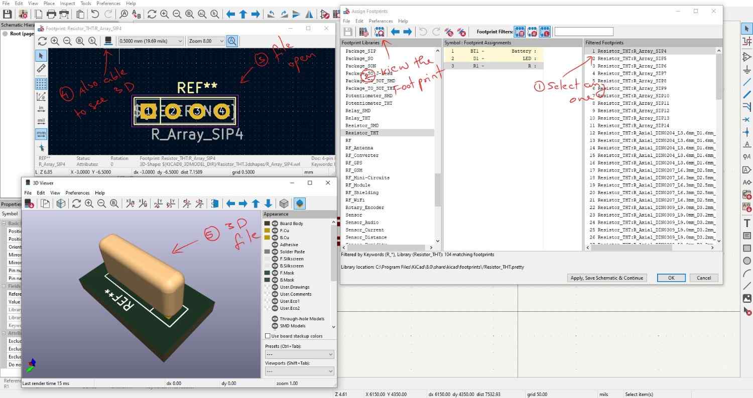
we will able to see the footprints of the particular components and its 3D visualization.

To access Fab Academy's library of symbols and footprints for KiCad, I downloaded the file from this link - Fablab Kicad resouces
For using this we need to add these into your kicad libraries, after select the preferences goes into the Manage symbol libraries

Then we can see the Fab in our symbol library, further there is the same step of Footprint library too. After exploring the tools I start the actual design, I taking out the necessary components which is I planned. I used the ATtiny85 Arranging it properly and connect it by using the wire.

I created the symbol library for the external USB connector in my case and update it in the schematic space and connect to the circuit.

And also create the footprint for the USB connector,then engage it with the USB connector for the PCB designing.

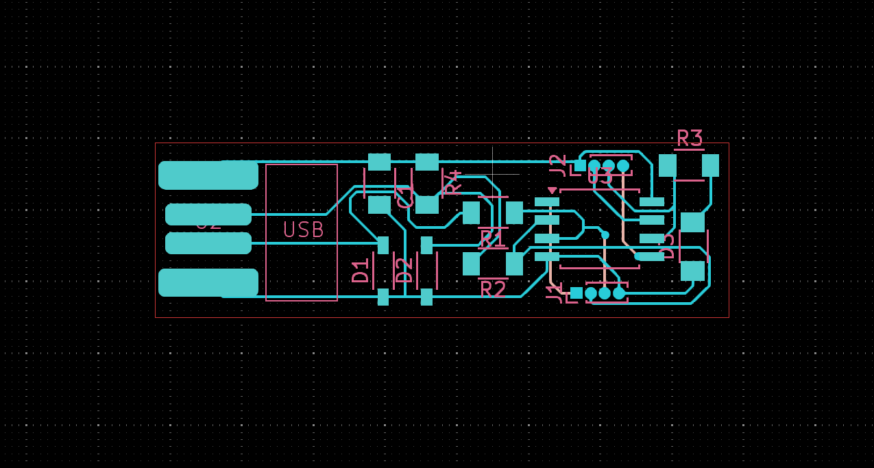
Then open the PCB editor, go to tools and update the PCB from schematic, at first it will comes into some set of orders, so we need to arrange it properly with our design constraints.
After arranging that perfectly connect the lines relative to each others with the help of referring lines


I export it into the gerber format (.gbr) and drill format (.drill)

