Week 10 - Output Device Design
Group Assignment
Group Assignment Summary – Output DevicesAs part of the group assignment, we measured and analyzed the power consumption of various output devices using laboratory instruments such as a bench power supply and multimeter. We observed the voltage and current requirements of the devices under different operating conditions and calculated their power consumption using the relationship Power = Voltage × Current. This exercise helped us understand the electrical requirements of output devices, power budgeting, and the importance of selecting appropriate power sources and driving circuits. Through hese measurements, we gained practical experience in evaluating output device performance and ensuring safe and reliable operation in embedded system designs
- Task: Measure the power consumption of an output device.
- Documentation: Record the process and results on the group work page.
- Reflection: On your individual page, explain what you learned from the group task.
Individual Assignment
- Task: Add an output device to a microcontroller board that you've designed.
- Programming: Write and upload a program to make the output device perform a function (e.g., blink an LED, drive a motor, sound a buzzer).
Hero Shot
Objective
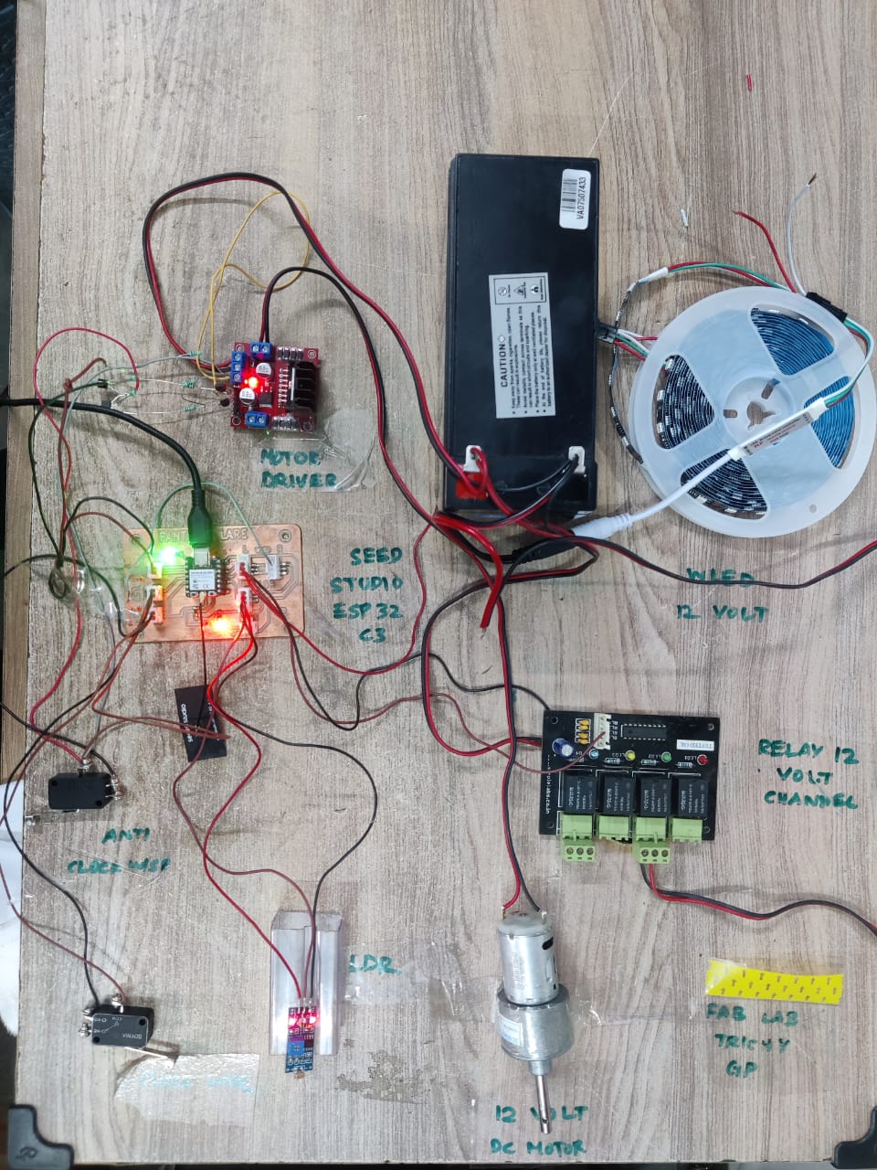
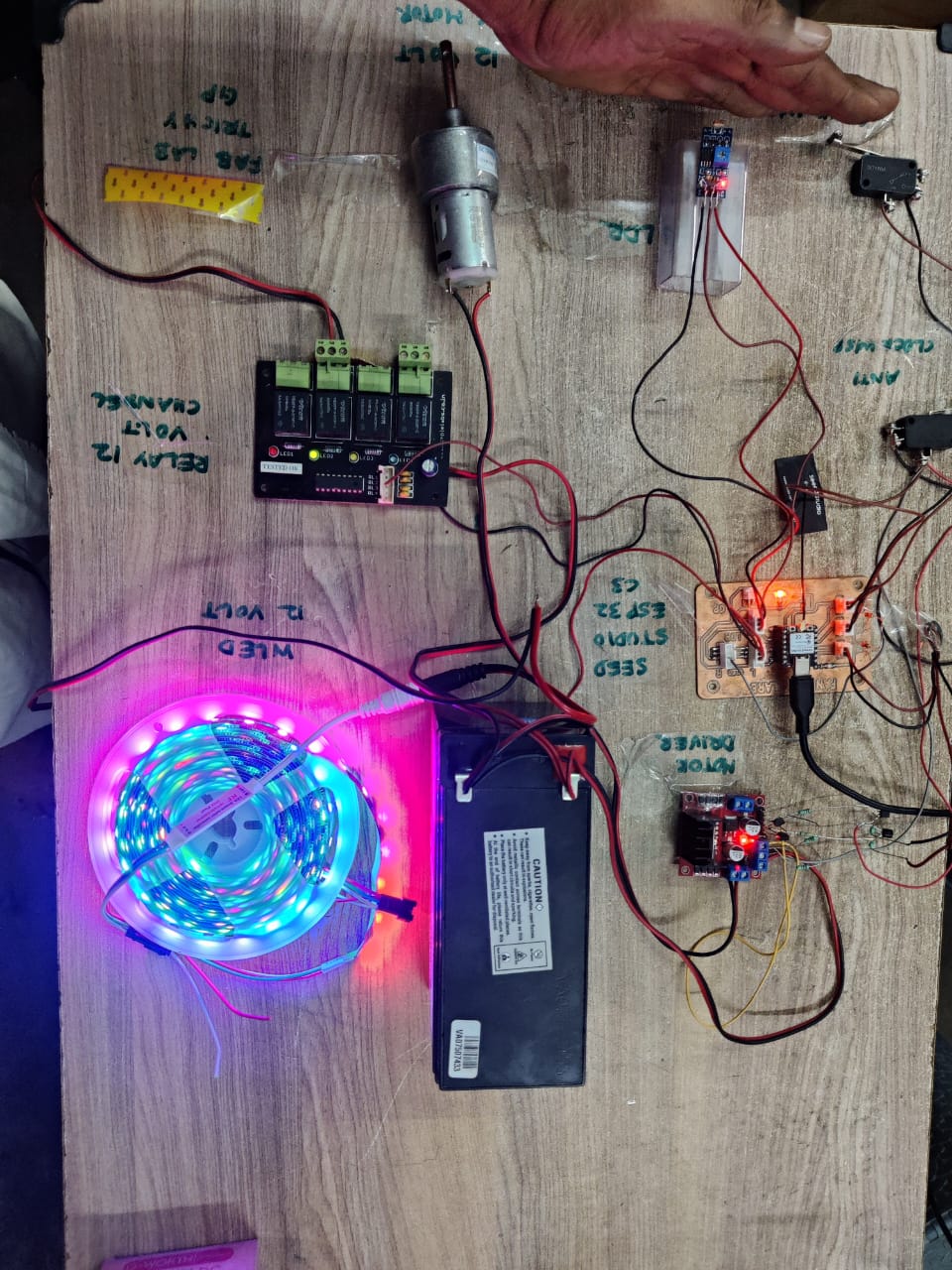
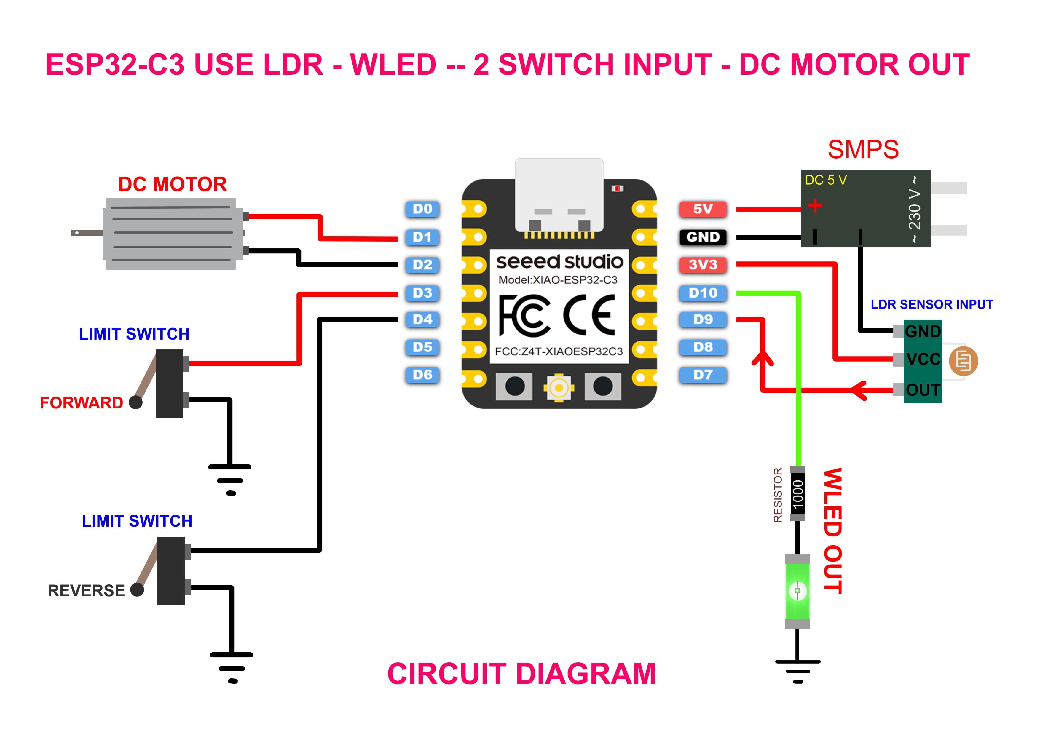
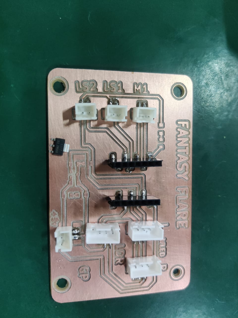
This week's goal is to control an output device using a custom-designed PCB. I have selected a DC Motor and a 12V LED as the primary output components. Both devices are controlled through input received from an LDR (Light Dependent Resistor) sensor. The LDR sensor detects ambient light levels and sends analog values to the microcontroller. Based on these readings, specific outputs are triggered.
When the surrounding light drops below a predefined threshold, the LDR signals the microcontroller to turn ON the 12V LED, simulating an automatic lighting system. Similarly, the DC motor is activated under certain lighting conditions, demonstrating real-world applications like ventilation or movement systems that respond to light changes. The system was implemented using a transistor-based driver circuit for the motor and a MOSFET to drive the high-power LED. This project helps in understanding the interaction between analog sensors and digital output control, as well as the importance of designing efficient and robust PCB layouts for handling both input an d output devices. The integration of sensor input and output control demonstrates a complete feedback loop in an embedded system.
circuit Design
I designed a circuit with a motor driver (L298N) to handle the DC motor and a transistor-controlled circuit to switch the 12V LED safely from the microcontroller.
Board Design in KiCad
Designing the relay module PCB using KiCad involves a systematic workflow. The process begins with creating a schematic diagram, which defines the logical connections between all electronic components.
Once the schematic is complete, each component must be assigned a suitable footprint that matches its physical size and shape. After that, the PCB layout is designed by placing components strategically and routing the copper traces to connect them.
To ensure reliable operation, power planes (such as ground and VCC) are defined for consistent power distribution. Finally, an Electrical Rules Check (ERC) and Design Rules Check (DRC) are performed to catch any errors or warnings before generating the Gerber files for fabrication.
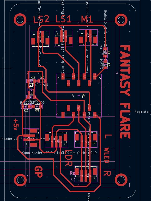
Shematic
Component placement and routing were done in KiCad. Design Rule Check passed successfully.
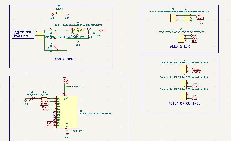
Pcb Board
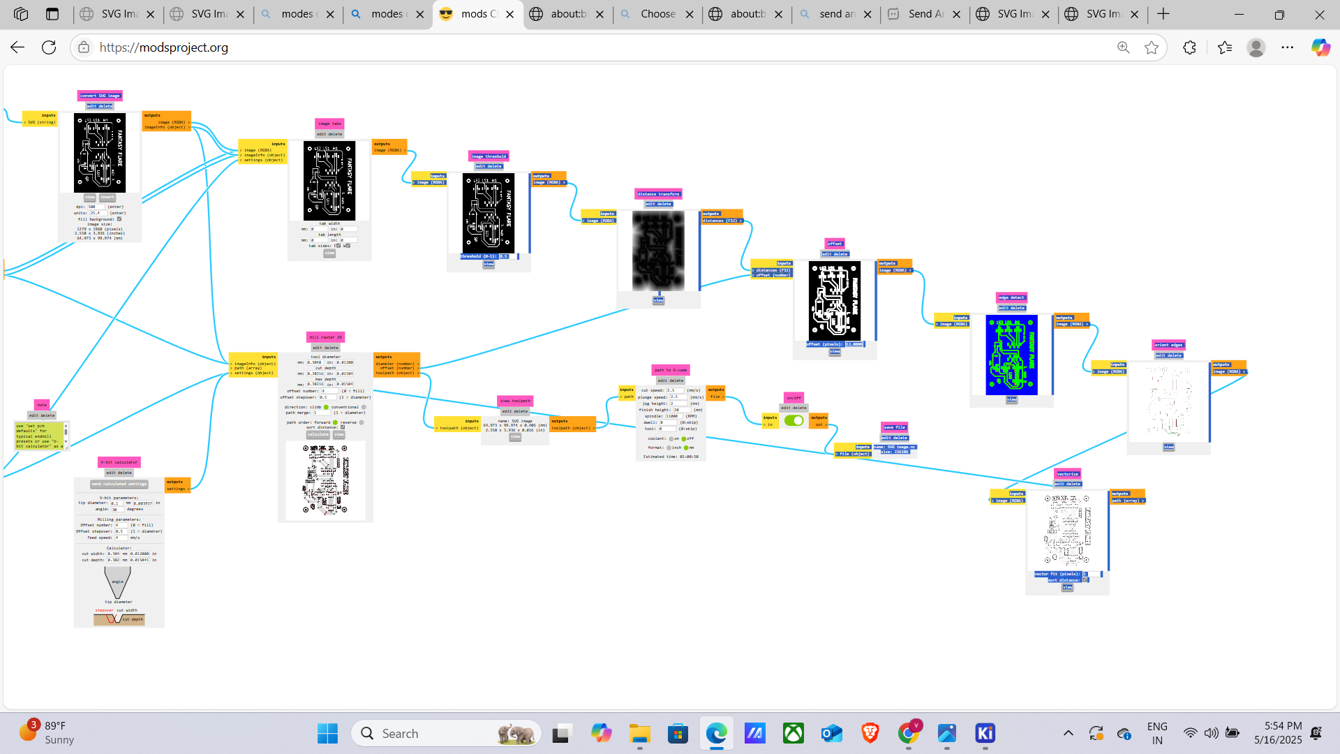
- In KiCad PCB Editor, go to File → Plot, set format to SVG, and
select necessary layers (e.g.,
F.Cu,Edge.Cuts). - Click Plot to export SVG files for each selected layer.
- Open SVGs in Inkscape to edit, align, or combine layers as needed.
- Import the edited SVG into MOD to generate toolpaths.
- Export G-code from the MOD tool for CNC milling, g.

To use MODs with the Wegstr PCB milling machine, export your board’s traces and outlines from KiCad as SVG files. Open MODs (mod.cba.mit.edu), load the appropriate PCB module (e.g., Roland mill outline or traces), and import the SVG. Set the tool diameter, cut depth, and offsets based on your bit size. Generate the toolpath and save the .nc G-code file. Then, open the Wegstr web interface or controller software, upload the G-code, and start the milling job. Ensure the board is properly fixed, and the tool zeroed on the copper surface for accurate PCB milling results.
The Wegstr PCB milling machine is a compact, desktop CNC tool designed for rapid prototyping of printed circuit boards. It enables users to mill single- or double- sided PCBs by carving copper-clad boards using precise toolpaths. Ideal for makers, educators, and electronics engineers, it supports various input formats like G -code and integrates with software like MODs and FlatCAM. With a user-friendly interface and high-precision spindle, Wegstr allows fast, chemical-free PCB fabrication. Its portability and ease of use make it suitable for labs or small workshops, offering an efficient alternative to traditional etching methods for creating custom electronics prototypes.
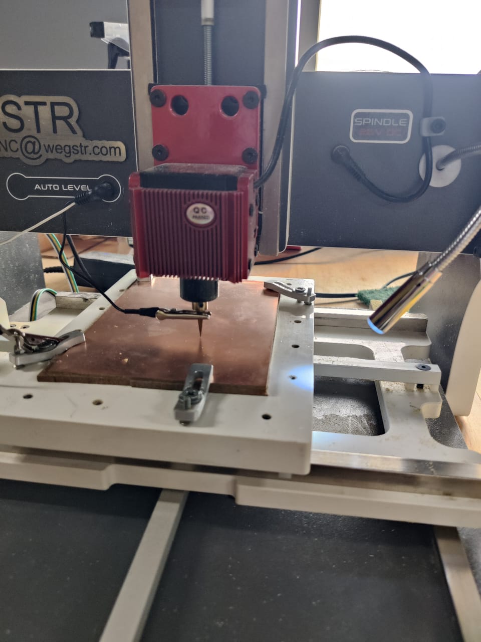
After the PCB is finely milled using the Wegstr machine, it must be carefully cleaned to ensure proper electrical performance and solderability. Begin by brushing off loose copper dust and debris using a soft anti-static brush. Next, use isopropyl alcohol (IPA) and a lint-free cloth or cotton swab to wipe the board surface, removing any residual particles or oil. Pay special attention to the milled tracks and pads. Cleaning not only improves the appearance of the board but also prevents shorts and improves solder adhesion during assembly. Ensure the board is completely dry before proceeding with component mounting or testing.
>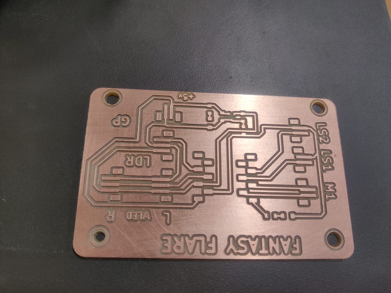
Once the PCB is cleaned and dry, female pin headers (female adaptors) are carefully soldered onto the designated tracks or pads. Align each header pin precisely with its corresponding hole or pad to ensure proper electrical contact. Use a fine-tipped soldering iron and appropriate solder wire to create clean, shiny joints without bridging adjacent pins. Proper soldering ensures reliable mechanical and electrical connections for plugging in modules or components. After soldering, inspect all joints for cold solder or shorts, and rework if necessary. This step completes the board’s assembly, making it ready for testing and integration into electronic projects.
Fabrication and Assembly
Arduino Code – Project Two: Digital Inputs
// Project Two - Digital Inputs

void setup()
{
    pinMode(10, OUTPUT);   // D10 LED OUT
    pinMode(2, OUTPUT);    // D0 Switch Input Identify LED
    pinMode(3, OUTPUT);    // D1 Motor One Lead
    pinMode(4, OUTPUT);    // D2 Motor another Lead

    pinMode(9, INPUT);     // D9 LDR Sensor Input
    pinMode(5, INPUT);     // D3 Switch 1 (Limit Switch 1)
    pinMode(6, INPUT);     // D4 Switch 2 (Limit Switch 2)
}

void loop()
{
    if (digitalRead(9) == HIGH)
    {
        digitalWrite(10, HIGH);  // LED ON when LDR detects light

        if (digitalRead(5) == LOW)
        {
            digitalWrite(2, HIGH);  // Identify LED ON
            digitalWrite(3, HIGH);  // Motor Forward
            digitalWrite(4, LOW);
        }
        else
        {
            digitalWrite(2, LOW);
            digitalWrite(3, LOW);
            digitalWrite(4, LOW);
        }

        if (digitalRead(6) == LOW)
        {
            digitalWrite(2, HIGH);  // Identify LED ON
            digitalWrite(3, LOW);   // Motor Reverse
            digitalWrite(4, HIGH);
        }
        else
        {
            digitalWrite(2, LOW);
            digitalWrite(3, LOW);
            digitalWrite(4, LOW);
        }
    }

    if (digitalRead(9) == LOW)
    {
        digitalWrite(10, LOW);     // Turn off LED
        digitalWrite(2, HIGH);     // Blink Identify LED
        delay(1000);
        digitalWrite(2, LOW);
        delay(1000);
    }
}
Components
- LDR (Light Dependent Resistor): Used to detect ambient light intensity.
- DC Motor – 300 RPM: Used as an output device to demonstrate motion control.
- Battery inefficiency
- Load variations
- Voltage drop under load
- Aging of the battery
- 12V LED: High-brightness LED used as a visual output based on LDR readings.
- Seeed Studio ESP32-C3: Custom-designed PCB to read LDR values and control outputs.
- L298N 2A Based Motor Driver Module: Motor driver for forward/reverse switch control.
- Buck Converter: Steps down 12V input to a stable 5V or 3.3V to safely power the ESP32-C3 and sensors.
- 12V Power Supply: Provides required power for the motor and LED.
- 12V Relay Module: switch the 12V motor ON and OFF
- Limit Switches (x2): Used to detect mechanical end positions and stop the DC motor automatically.
1. Power Consumption of the Motor
Use the basic formula:
Power (W) = Voltage (V) × Current (A)
Voltage = 12V
Current = 0.8A
So:
Power = 12V × 0.8A = 9.6 Watts
2. Battery Capacity and Estimated Run Time
The battery is rated:
12V, 7Ah (Amp-hours)
To estimate how long the battery will run the motor:
Run Time (hours) = Battery Capacity (Ah) / Motor Current (A)
Battery: 7Ah
Motor current: 0.8A
So:
Run Time = 7Ah ÷ 0.8A = 8.75 hours
Important Real-World Considerations
This is a theoretical maximum run time.
Real run time is often 70–80% of this due to:
Practical run time ≈ 7 to 7.5 hours
Problem I Encountered During Output Device Assignment
The ESP32-C3 operates at 3.3V logic and cannot directly drive high-current devices like a 12V motor. Initially, attempting to control the motor directly caused voltage instability and risked damaging the microcontroller.
Solution:
I used a relay module to safely switch the 12V motor ON and OFF. The relay’s input was triggered by the ESP32 GPIO, and it isolated the high-voltage motor circuit from the low-voltage logic. This approach allowed me to control the motor safely using digital HIGH/LOW signals.
Working Process
When an obstacle or darkness is detected by the LDR (Light Dependent Resistor) module, it changes its resistance, which is read as a signal by the microcontroller. This input is processed by the Seeed Studio ESP32-C3 board programmed using the Arduino IDE. Upon detection, the microcontroller activates a 12V LED as a visual indicator and powers the DC motor. The motor’s operation is controlled through two limit switches, which define its travel limits, ensuring it moves only within a safe range. This mechanism demonstrates a simple yet effective light-triggered automation system.
As soon as the light level returns to normal and is detected by the LDR, the system immediately stops both the motor and the LED, halting all movement and conserving energy. This quick response ensures the motor only operates during specific conditions (i.e., darkness or blockage), making the setup ideal for light-sensitive automation projects such as smart barriers, object detection systems, or interactive displays. The entire process runs on the ESP32-C3 board, which provides Wi-Fi/BLE capabilities, offering potential for further IoT-based enhancements.