As part of the group assignment, we analyzed the behavior of input devices by observing their analog and digital
signals using measurement tools. We used a multimeter and oscilloscope to understand how sensor outputs change in response
to physical conditions. This exercise helped us understand voltage levels, signal transitions, and the difference between
analog and digital sensor outputs.
Measure something: Add a sensor to a microcontroller board that you have designed and read it.
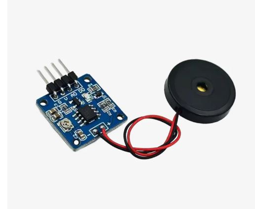
A sensor is a device that detects or measures a physical property and converts it into a signal.
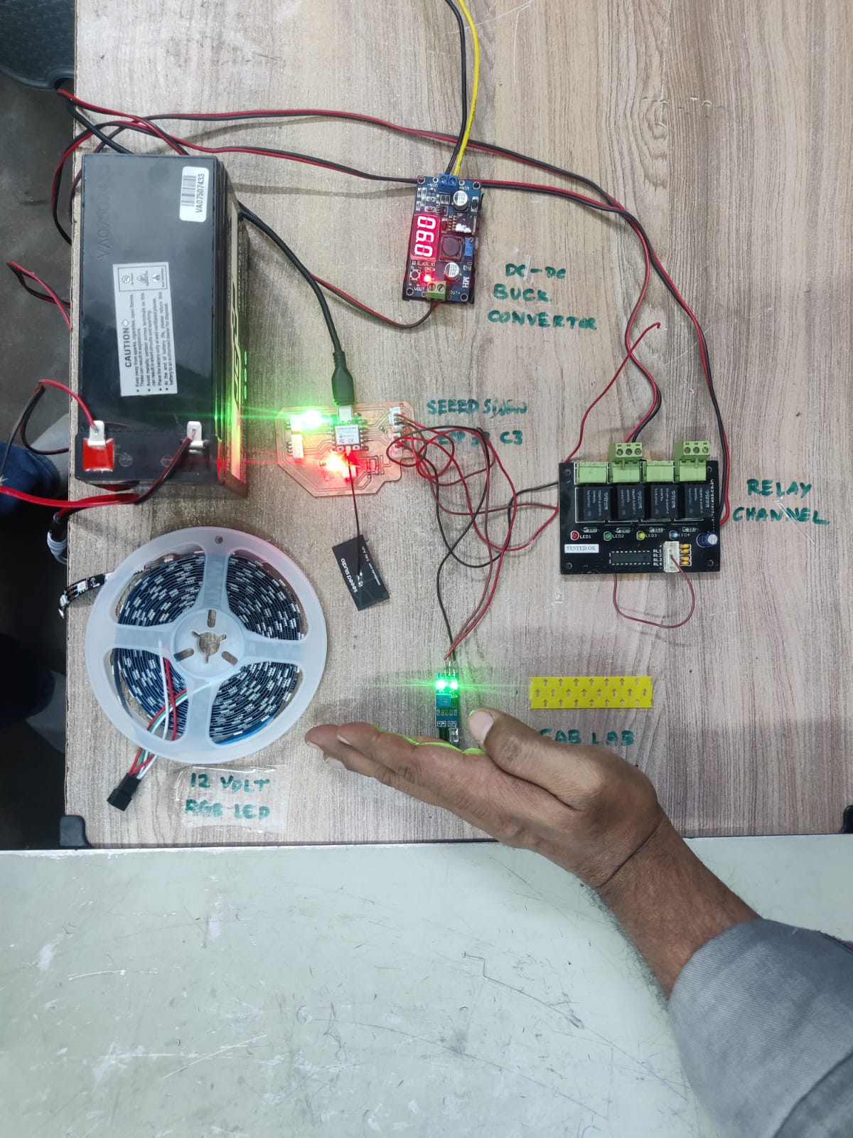
Hero Shot
>
Input Board Design In Few Steps
Board Design in KiCad
The Input Device PCB was designed using KiCad. Components such as the IR sensor connector, Seeed Studio XIAO ESP32-C3
connector, resistors, and power connections were placed according to the circuit requirements. Proper routing was
carried out to ensure reliable signal transmission and easy assembly.
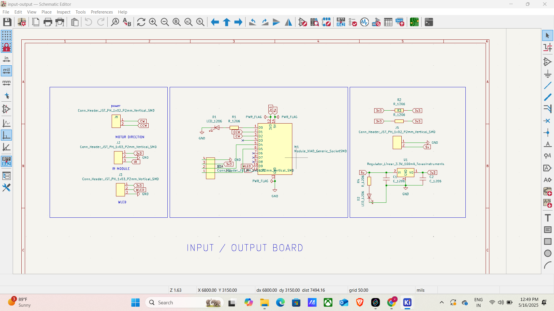
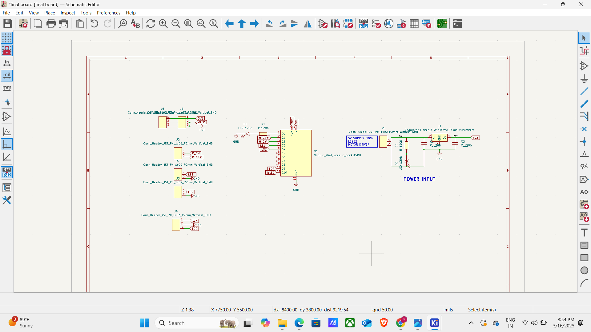
Schematic
The schematic was created in KiCad to define the electrical connections between all components. It serves as the
blueprint of the circuit and helps verify that the sensor, microcontroller, and supporting components are connected
correctly before PCB layout design.
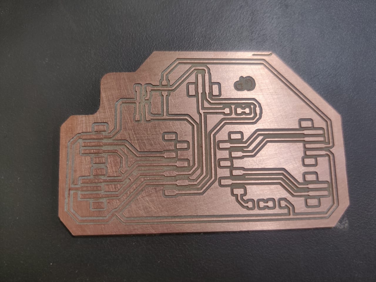
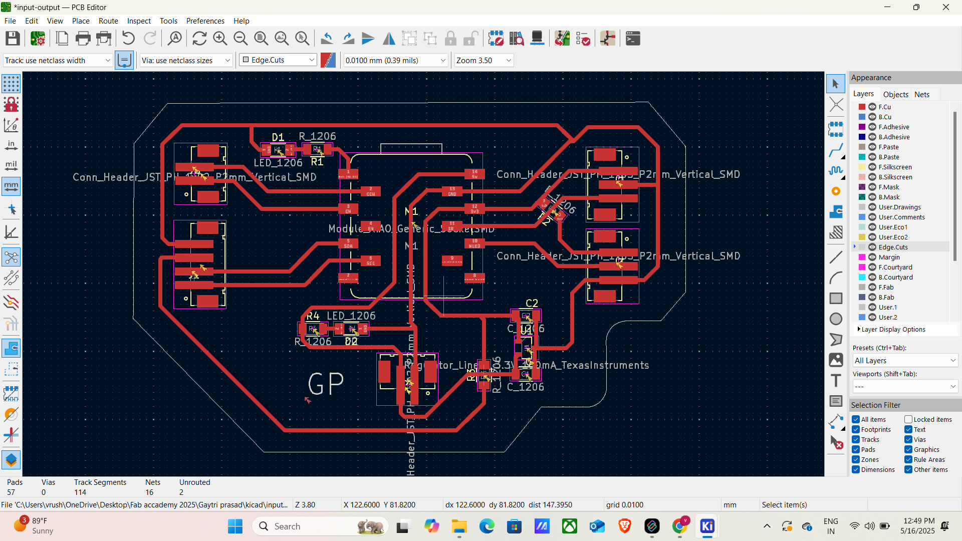
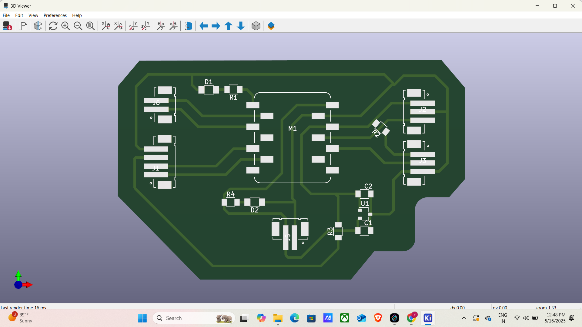
PCB Board
After completing the schematic, the PCB layout was developed in KiCad. Components were arranged efficiently, and traces were
routed to create a compact and manufacturable board. Design Rule Checks (DRC) were performed to ensure there were no routing
or clearance errors.
PCB
The finalized PCB layout was reviewed and prepared for fabrication. The board design included all required traces, pads,
and connectors needed for interfacing the IR sensor with the Seeed Studio XIAO ESP32-C3.
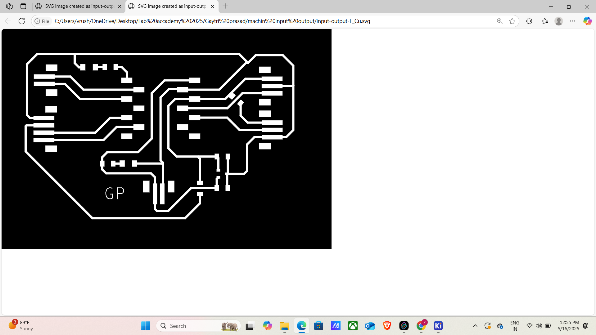
SVG
The PCB traces and outline were exported as SVG files from KiCad. These SVG files were used as the input for generating
machining toolpaths required for PCB milling.
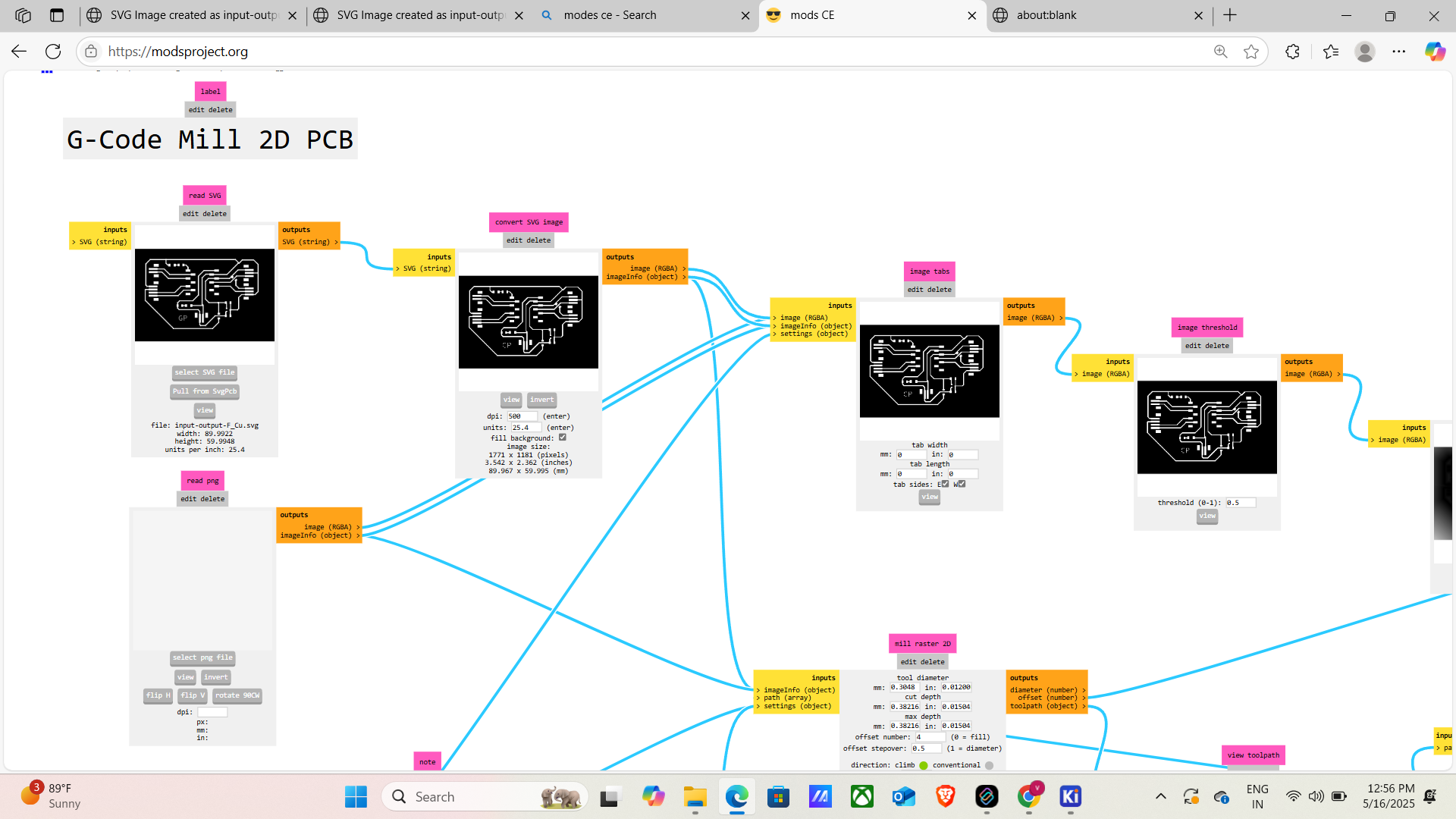
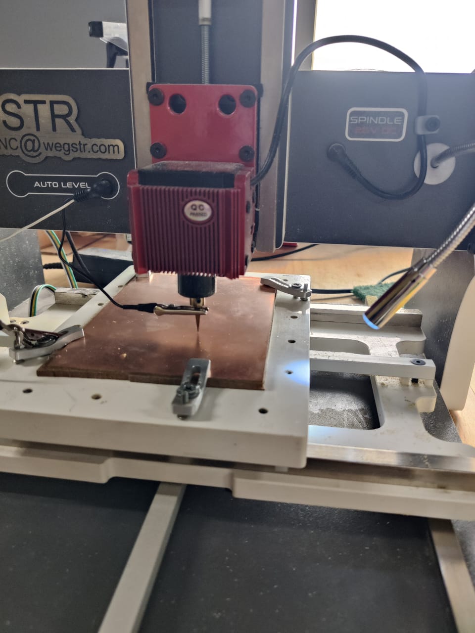
G-Code in MODs with the Wegstr PCB Milling Machine
The exported SVG files were imported into MODs software. Appropriate milling parameters such as tool diameter,
cut depth, and feed rate were configured. MODs then generated the G-code required to machine the PCB on the
Wegstr PCB milling machine.
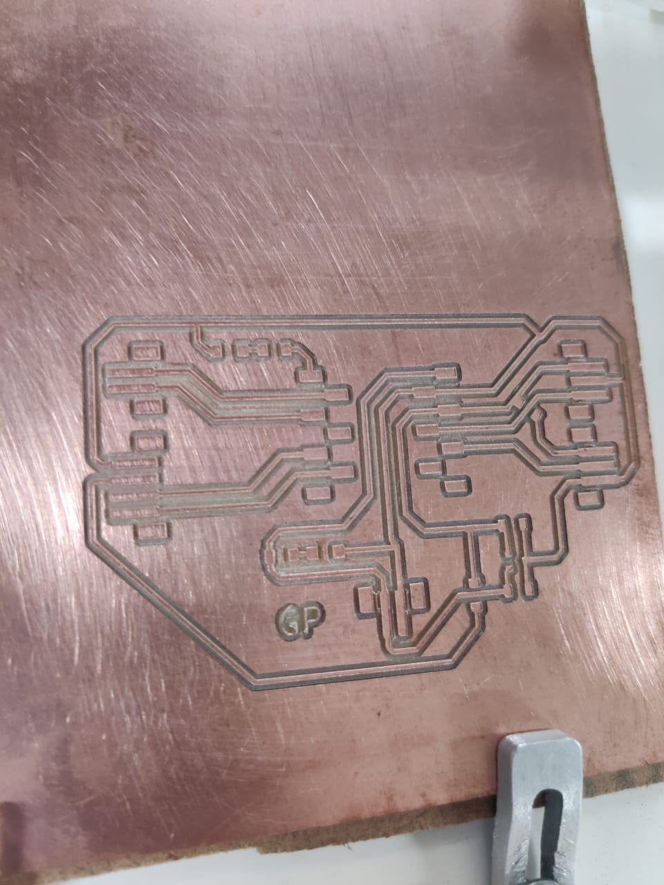
PCB is Finely Milled Using the Wegstr Machine
The generated G-code was loaded into the Wegstr PCB milling machine. The machine accurately milled the PCB traces
and board outline, producing a clean and precise circuit board ready for component soldering
🔍 What is a Sensor?
In simple words:
A sensor is like a human sense organ (eyes, ears, skin). It helps machines or systems "sense" their
surroundings.
Why Do We Use Sensors?
Measure real-world conditions — temperature, pressure, light, motion, etc.
The objective of this project is to design, develop, and test an electronic input device using an Infrared (IR)
sensor to control an RGB LED. As part of my Fab Academy 2025
assignment on input devices, this project demonstrates how sensor data can be used to influence output behavior.
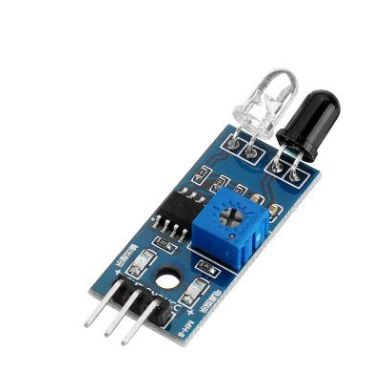
The IR sensor detects the presence or proximity of an object
and sends an analog or digital signal to a microcontroller. This signal is then interpreted to control the color
or intensity of an RGB LED, enabling real-time interaction
between input and output components. The project involves designing a custom PCB in KiCad, programming the
microcontroller to read IR sensor data, and writing logic to
control the RGB LED based on sensor input. This assignment enhances my understanding of sensor integration,
analog/digital signal processing, and embedded control,
contributing to my overall goal of mastering digital fabrication and interactive electronics.
Why I Used ESP32-C3 for Input Week
I selected the ESP32-C3 module as the microcontroller for input device testing due to its robust wireless
communication, rich peripheral support, and efficient processing
capabilities. It supports multiple input interfaces like analog sensors, joysticks, and buttons, enabling
real-time data acquisition and wireless transmission.
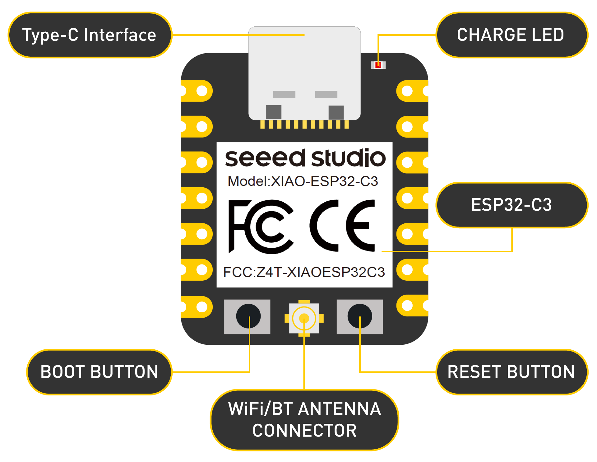
ESP32-C3 Overview
The ESP32-C3 is a low-cost, low-power 32-bit RISC-V microcontroller with built-in Wi-Fi and Bluetooth LE 5.0, making
it ideal for IoT and connected input applications. It offers strong security, a rich set of GPIOs, and a flexible
pin matrix.
Technical Specifications — ESP32-C3
Feature
Specification
CPU
32-bit RISC-V single-core @ up to 160 MHz
SRAM
400 KB
ROM
384 KB
Flash Memory
External (typically 4 MB via SPI)
EEPROM
Not available (can be emulated in flash)
Operating Voltage
3.0V to 3.6V
Wi-Fi
2.4 GHz, IEEE 802.11 b/g/n (up to 150 Mbps)
Bluetooth
Bluetooth 5.0 LE (Mesh, Long Range)
Digital I/O Pins
22 GPIOs (GPIO0–GPIO21)
ADC
12-bit resolution, 6 channels (GPIO0 to GPIO5)
UART
2 UART interfaces
SPI
2 (SPI0 reserved for flash, SPI1 for general-purpose use)
I2C
1 (SDA/SCL can be mapped to any GPIOs)
PWM
Available on all GPIOs
Timers
Multiple hardware timers
USB
Native USB 2.0 Full-Speed (GPIO19: D-, GPIO20: D+)
Active ~130 mA, Light Sleep ~0.8 mA, Deep Sleep ~5 µA
Package
QFN32 (5 mm × 5 mm)
Supported Tools
ESP-IDF, Arduino IDE, PlatformIO, MicroPython
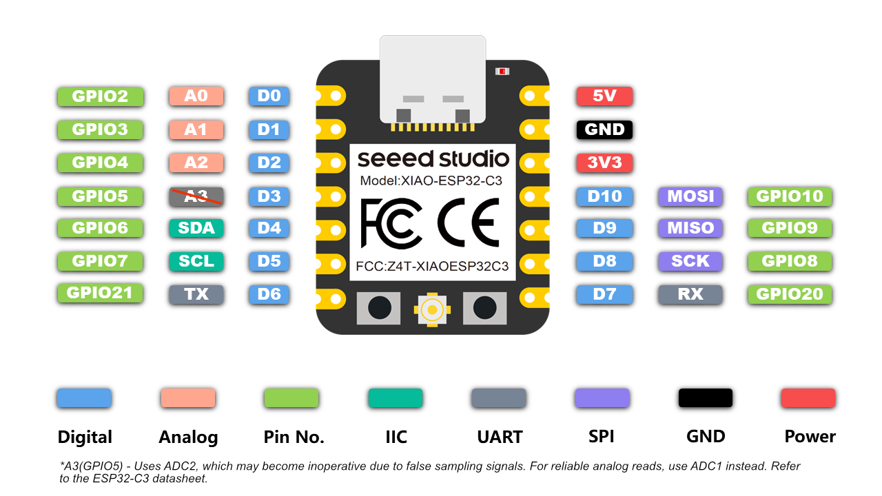
Pinout Overview — ESP32-C3
Digital I/O (GPIO0–GPIO21)
All pins support digital I/O, PWM, pull-up/down, and peripheral functions.
GPIOs support 20–40 mA output current (dependent on function).
GPIO0: Used for boot mode during flashing.
GPIO1 (TX), GPIO3 (RX): Default UART.
GPIO9 & GPIO10: Typically connected to internal flash — avoid for I/O.
GPIO19 & GPIO20: USB D- and D+ (for native USB).
Analog Input (ADC1)
Channels: 6 ADC inputs (GPIO0 to GPIO5)
Resolution: 12-bit
Voltage Range: 0–3.3V
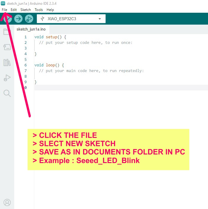
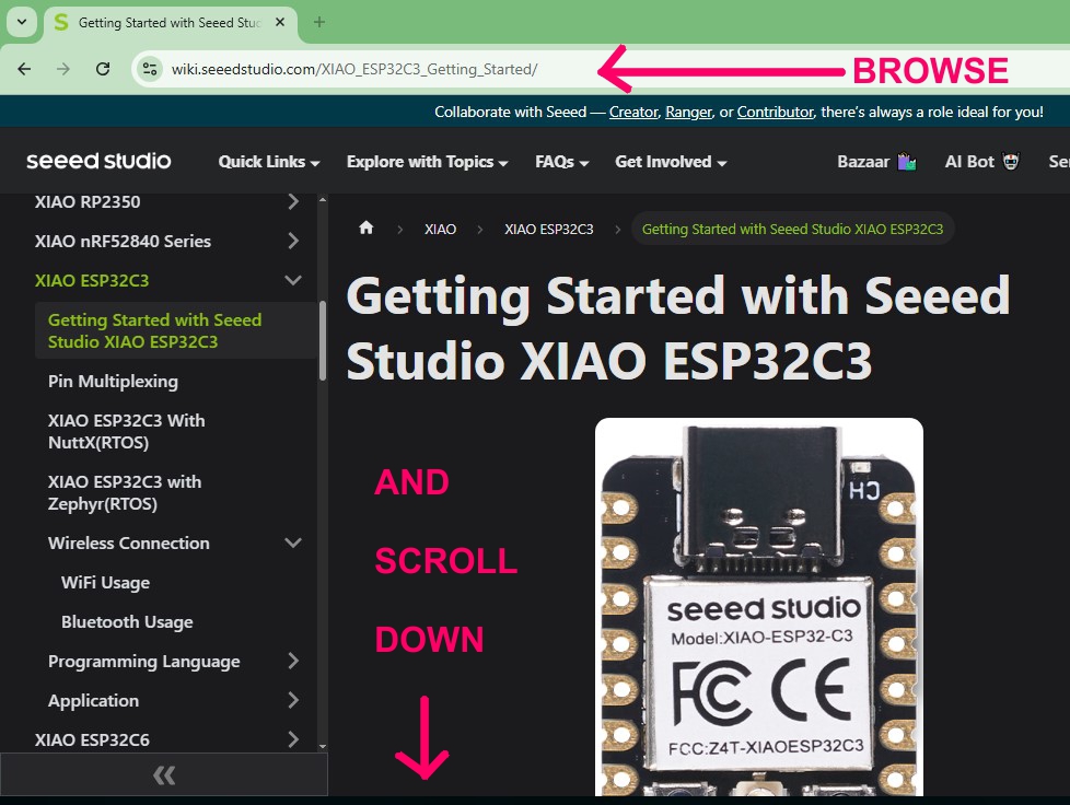
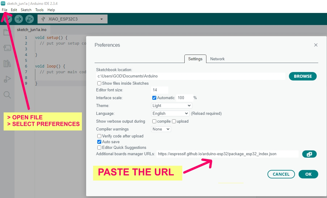
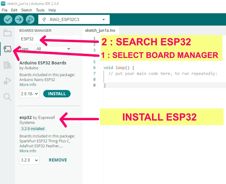
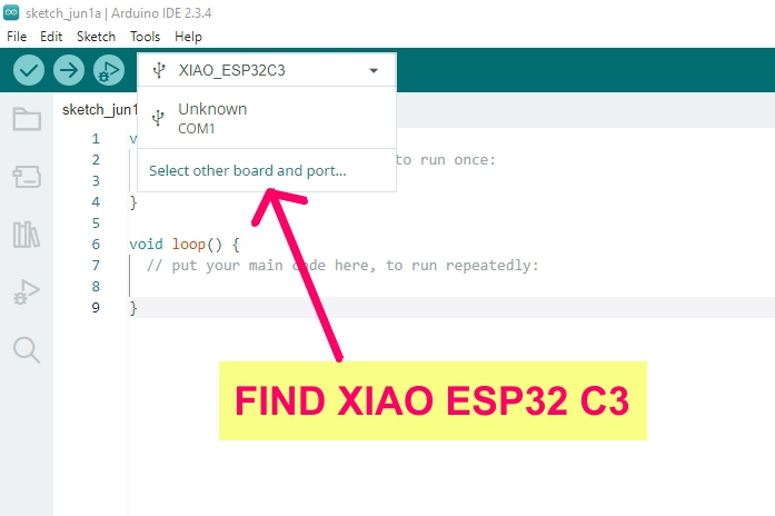
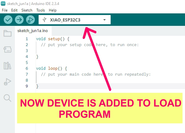
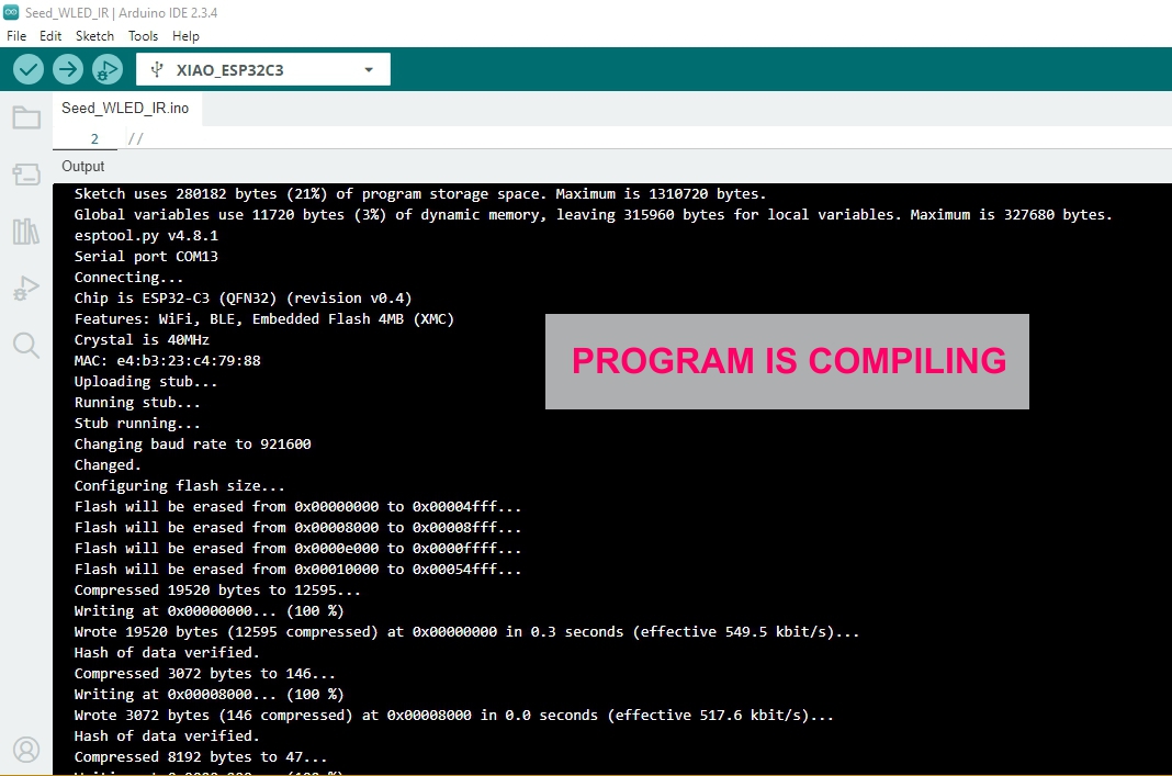
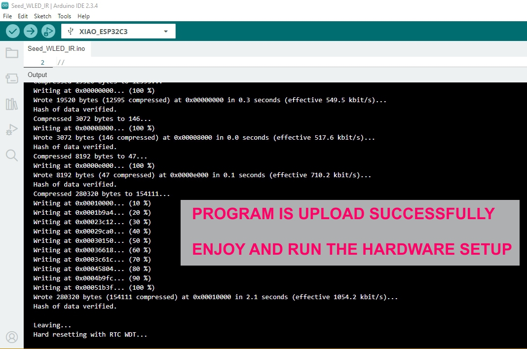
Configure and Examine the Board
Refer upto Programming in Week-08 Electronics Production
Note: The detailed PCB fabrication process, board configuration, software installation, and initial
board testing procedures have already been documented in Week 08 – Electronics Production. To avoid
repeating the same steps and images across multiple assignments (Input Devices, Output Devices,
Networking & Communications, and Final Project), only the assignment-specific modifications and
results are presented here.
For the complete board configuration and software setup procedure, please refer to:
Week 08 – Electronics Production,
7. Configure and Examine the Board
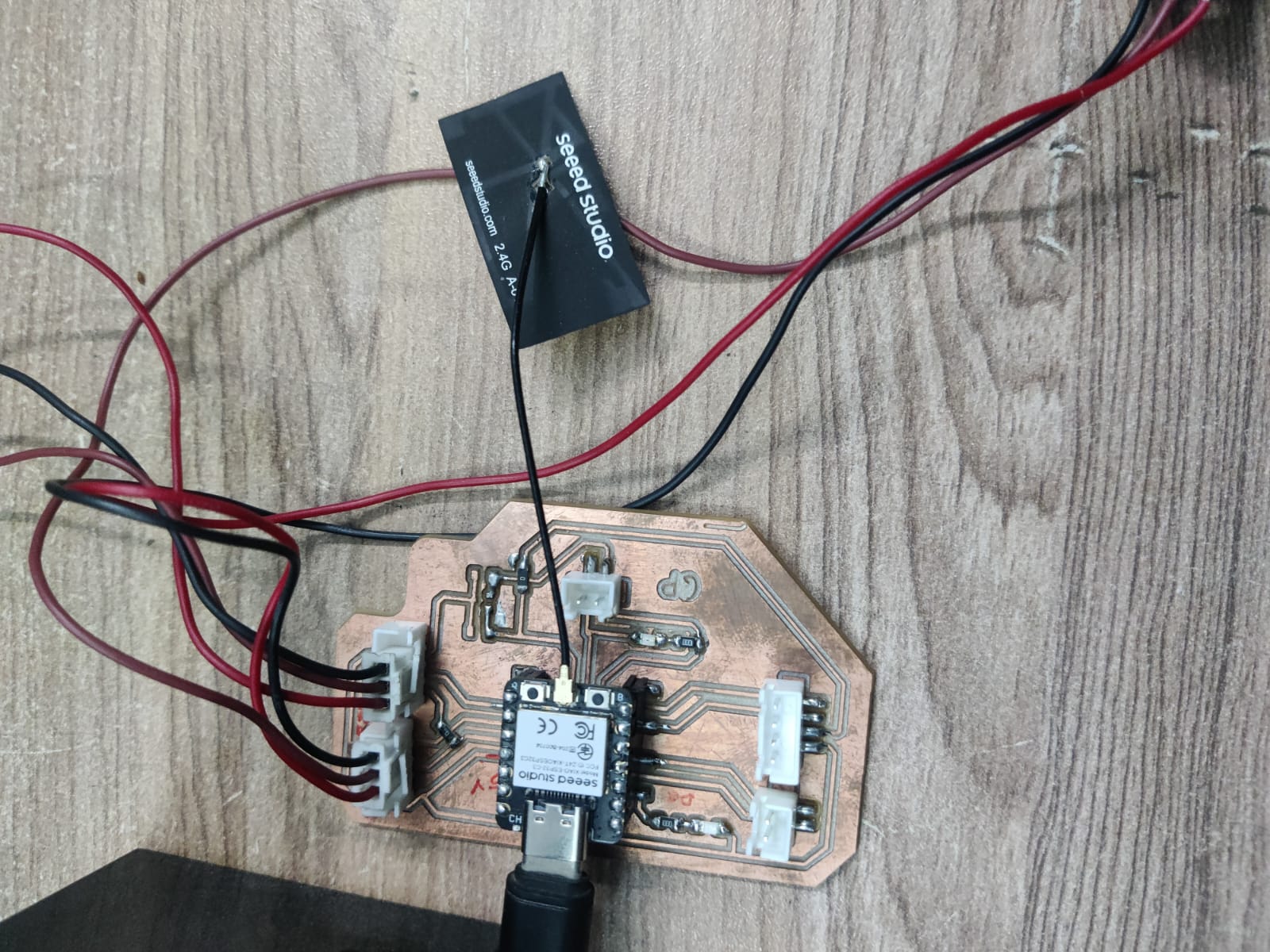
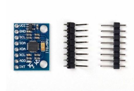
A compact Wi-Fi + BLE microcontroller that reads input signals from the IR sensor and controls output devices like RGB LEDs and a relay.
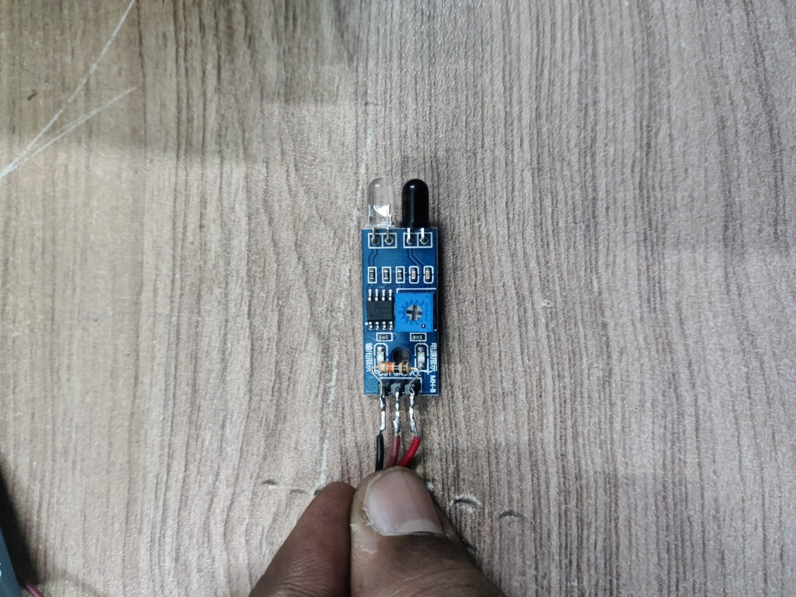
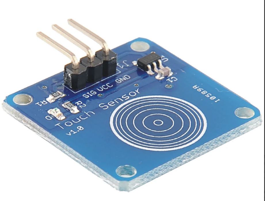
2. IR Sensor Module
Acts as the input device. Receives infrared signals (e.g., from a remote) and sends data to the ESP32 for processing.
3. Common Cathode RGB LED
A 4-pin LED capable of emitting Red, Green, and Blue light. Controlled using PWM signals from the ESP32 to create various colors.
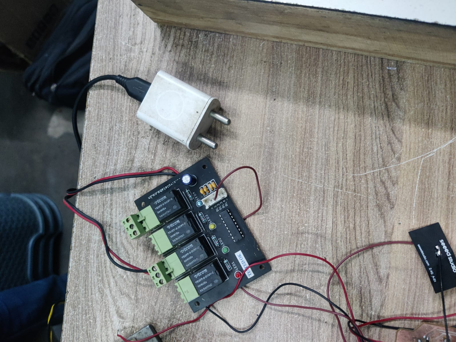
4. Relay Module (5V)
Allows the ESP32 to control high-power AC/DC devices. Acts as an electrically isolated switch.
5. Buck Converter (e.g., LM2596)
Steps down battery voltage (e.g., from 7.4V or 12V) to 5V or 3.3V to safely power the ESP32 and other components. Ensures stable voltage supply.
6. Custom PCB Board
A soldered board that organizes and connects all components. Useful for compactness, durability, and debugging.
7. Battery (Li-ion or 2S Pack)
Supplies raw DC voltage (often higher than needed). Used with a buck converter to provide regulated voltage to the circuit.
8. Resistors (220Ω–330Ω)
Protect the RGB LED by limiting current. Connected in series with each color pin.
9. Capacitors (e.g., 0.1µF)
Help filter noise and stabilize the ESP32’s power supply, especially important when using relays or motors.
10. Male/Female Header Pins
For modularity and easy replacement of components during testing. Useful for sensors or RGB LED connection.
11. Jumper Wires / Connectors
For flexible connections, especially between the buck converter output and ESP32 power input (3V3 or 5V).
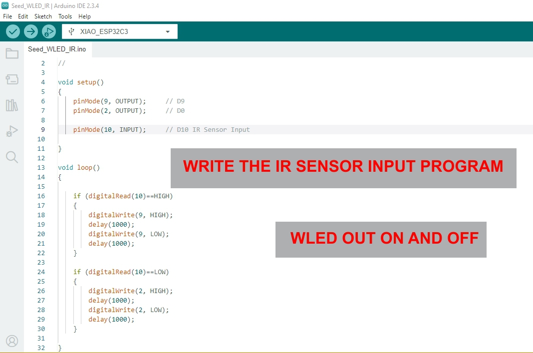
Digital Inputs
This Arduino project reads a digital input from pin 10 and controls two LEDs connected to pin 9 and pin 2. Depending on the input state, the appropriate LED blinks every second.
Code Explanation:
Pin 10: Set as INPUT, used to detect a digital signal (e.g., from a switch).
Pin 9: Set as OUTPUT, turns ON/OFF when input is HIGH.
Pin 2: Set as OUTPUT, turns ON/OFF when input is LOW.
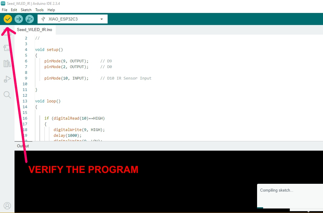
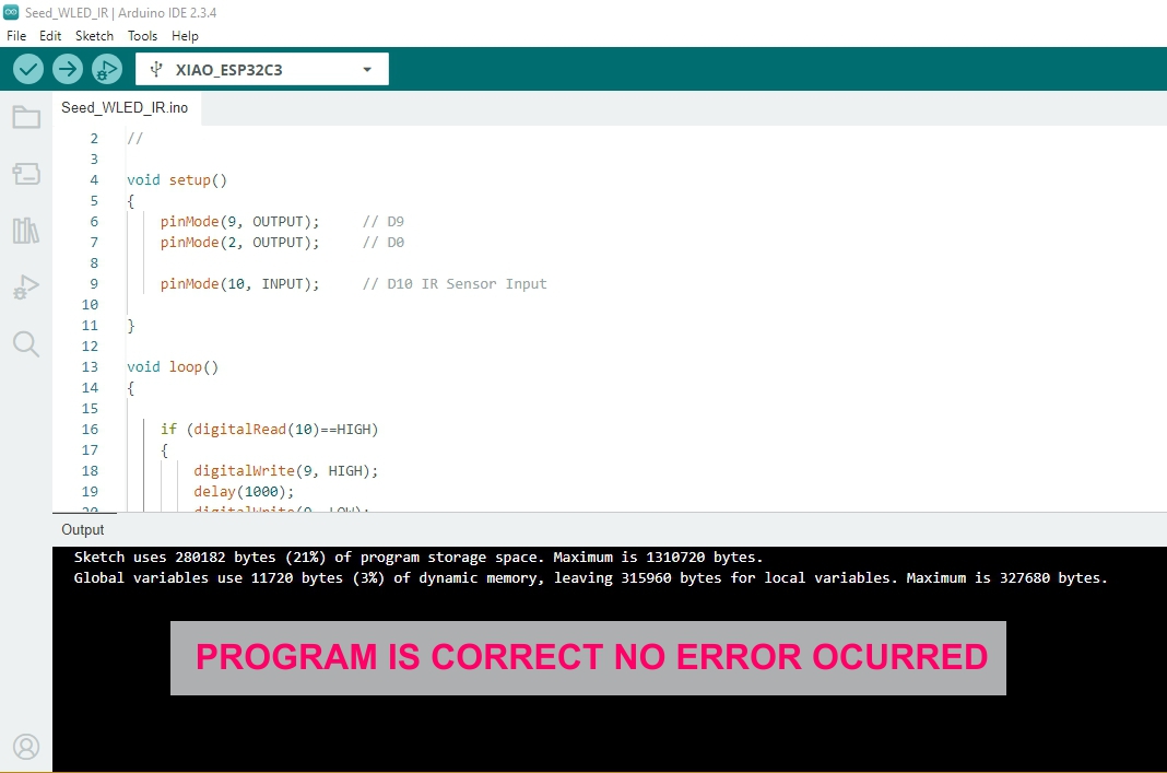
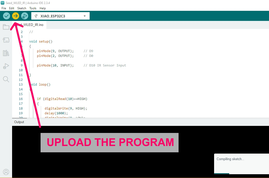
Arduino Code:
void setup()
{
    pinMode(9, OUTPUT);   // Output 1
    pinMode(2, OUTPUT);   // Output 2
    pinMode(10, INPUT);   // Input
}

void loop()
{
    if (digitalRead(10) == HIGH)
    {
        digitalWrite(9, HIGH);
        digitalWrite(2, LOW);  // Ensure other LED is off
        delay(1000);
        digitalWrite(9, LOW);
        delay(1000);
    }
    else
    {
        digitalWrite(2, HIGH);
        digitalWrite(9, LOW);  // Ensure other LED is off
        delay(1000);
        digitalWrite(2, LOW);
        delay(1000);
    }
}
Note: If using a pushbutton or switch on pin 10, ensure proper pull-up or pull-down resistors are used to prevent floating input states.
For my Fab Academy Input Devices assignment, I designed a simple interactive system using an
IR (Infrared) sensor to control an RGB LED light strip. The IR sensor acts
as the input device, continuously emitting and detecting infrared signals. Under normal conditions,
when the IR beam is not obstructed, the system interprets this as a "clear" state. In response, the RGB
LED light strip remains active, cycling through colors or blinking continuously using
PWM (Pulse Width Modulation) signals controlled by the
Seeed Studio XIAO ESP32-C3 microcontroller.
When an object blocks the IR sensor (such as a hand or any solid object), the IR receiver detects
the absence of the reflected signal. This triggers a change in logic on the ESP32, which is programmed
to immediately turn off the RGB LED strip. This simulates an interactive response where
user presence or motion alters the lighting behavior. The RGB LED remains off until the IR sensor is
no longer blocked. This project demonstrates how digital input sensing and
PWM-controlled outputs can be combined in real-time interaction using simple components.
It also highlights the practical use of microcontrollers to bridge input sensing and visual feedback in
creative applications.
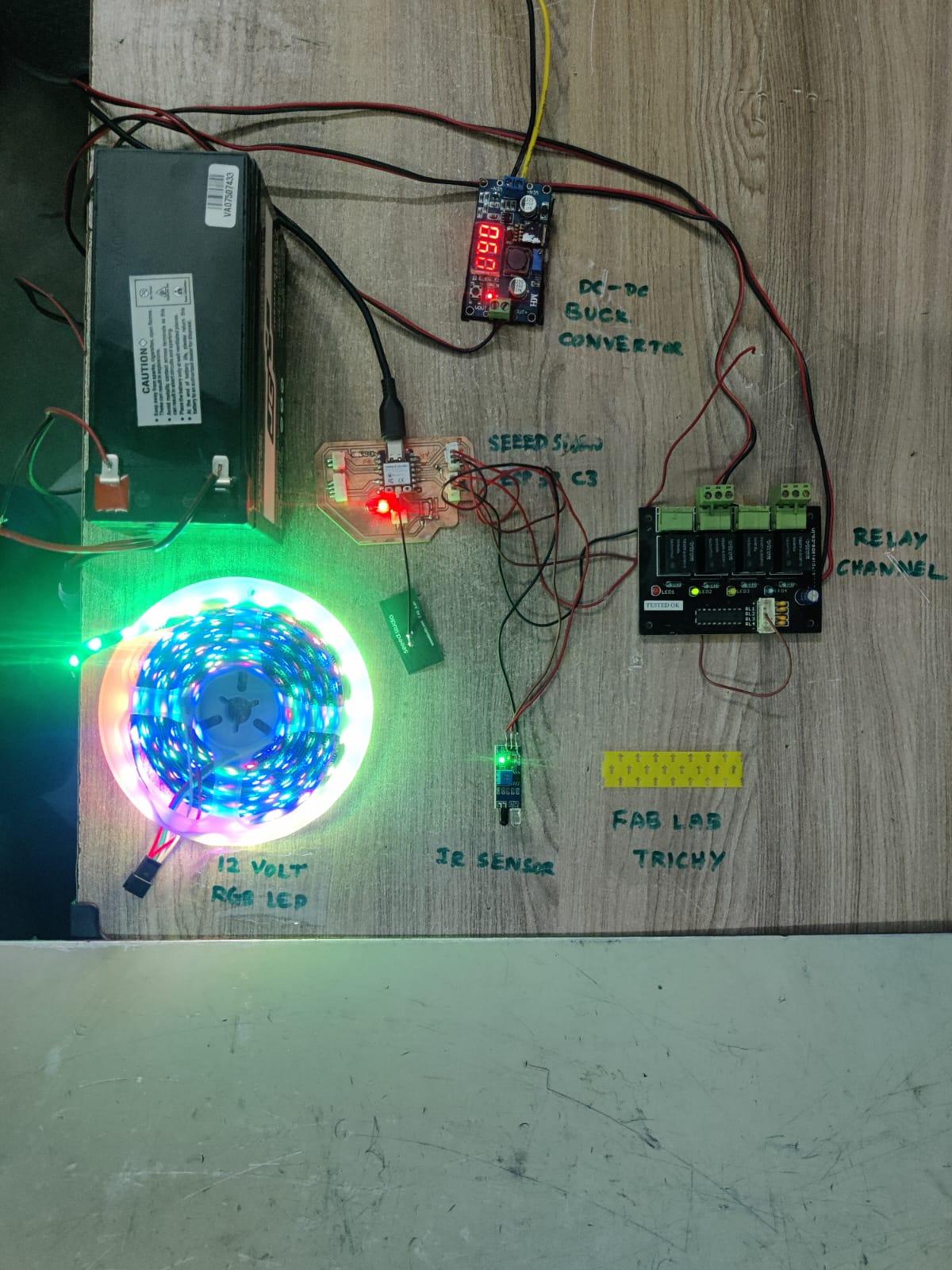
Problems Encountered and How I Fixed Them
During my input device assignment, I integrated both low-power input (IR sensor) and high-power output (12V RGB LED strip) components. This required careful voltage management and safe control circuitry. Here are the problems I faced and the solutions I implemented:
1. Multiple Voltage Levels & Power Supply
Problem:
I used a 12V, 7A sealed lead-acid battery to power the entire setup. While this was suitable for the RGB LED strip, my microcontroller (ESP32-C3) and sensor required 3.3V and 5V respectively. Supplying the wrong voltage could damage components.
Fix:
I added a buck converter (DC-DC step-down regulator) to derive both 5V and 3.3V outputs from the 12V battery:
5V was used for powering the IR sensor.
3.3V was used to safely power the ESP32-C3 board.
This allowed all components to operate off a single 12V battery without compromising safety.
What I Learned
Through this assignment, I learned how to design and fabricate a custom PCB for an input device using KiCad
and PCB milling techniques. I gained experience in interfacing an IR sensor with the Seeed Studio XIAO ESP32-C3
and understanding how digital sensor signals can be read and processed by a microcontroller. I also learned
how to use PWM signals to control RGB LED lighting effects and how to integrate input sensing with output control.
Additionally, I improved my skills in soldering, programming, debugging, and testing electronic circuits to ensure
reliable operation.
Conclusion
This assignment helped me understand the complete workflow of developing an embedded input system, from circuit
design and PCB fabrication to programming and testing. By successfully connecting an IR sensor to control an RGB
LED strip, I demonstrated how a microcontroller can process sensor inputs and generate interactive visual outputs.
The project strengthened my knowledge of sensor integration, PWM control, and real-time interaction, which will
be valuable for developing more advanced electronic systems and for implementing input devices in my final project.
 /div>
/div>