Group Assignments
Group Assignment Summary
As part of the group assignment, we tested the design rules and capabilities of our 3D printers by printing a characterization model containing features such as overhangs, bridges, clearances, wall thicknesses, holes, and support structures. The objective was to identify the printer's limitations and determine the optimal settings for producing accurate and reliable prints. Through these tests, we evaluated print quality, dimensional accuracy, and the effects of different design parameters on the final output. This exercise helped us understand the strengths and constraints of additive manufacturing and provided valuable guidelines for designing successful 3D-printed parts in future projects.
Visit Our Group Assignment HereIndividual assignment:
Design and 3D print an object (small, few cm3, limited by printer time) that could not be easily made subtractively 3D scan an object (and optionally print it)
Learning outcomesIdentify the advantages and limitations of 3D printing
Apply design methods and production processes to show your understanding of 3D printing.
Demonstrate how scanning technology can be used to digitize object(s)
Have you answered these questions?
Linked to the group assignment page
Explained what you learned from testing the 3D printers
Documented how you designed and 3D printed your object and explained why it could not be easily made subtractively
Documented how you scanned an object
Included your original design files for 3D printing
Included your hero shots
 >
>3D Scanning
Introduction to 3D Scanning
3D scanning technology captures the physical shape and dimensions of an object or environment and converts it into a digital 3D model. This process utilizes various techniques such as laser scanning, structured light, and photogrammetry. These technologies have seen rapid advancements, making them indispensable across multiple industries.
Types of 3D Scanning Technologies
Laser Scanning
Uses laser beams to measure distances and create high-accuracy 3D models. Used in architecture, engineering, and manufacturing. Structured Light Scanning
Projects patterns of light onto an object and measures distortions to create a 3D model. Common in healthcare and consumer electronics.
PhotogrammetryUses multiple 2D images taken from different angles to reconstruct a 3D model. Applied in archaeology, gaming, and cultural heritage preservation. Time-of-Flight (ToF) Scanning
Measures the time light takes to reflect back from an object to determine distance. Used in robotics and autonomous vehicles.
Photogrammetry: Overview, Applications, and AdvancementsWhat is Photogrammetry?
Photogrammetry is a 3D scanning technique that reconstructs accurate 3D models of objects, landscapes, or
buildings using multiple 2D images taken
from different angles. These images are processed using specialized software to analyze visual data and create
a
high-resolution digital model.
Image Capture A camera (drone, DSLR, or even a smartphone) takes multiple overlapping images of an object or environment. Feature Detection Software identifies common points in different images to determine depth and shape. 3D Reconstruction Algorithms triangulate the 3D coordinates of these points, generating a mesh and texture for the final 3D model. Post-Processing The model can be refined, textured, and exported for various applications like CAD, VR, or GIS mapping.
Mobile Photogrammetry Apps (iOS & Android)
1. Polycam (iOS, Android)
Easy to use, great for beginners
Uses LiDAR (on compatible iPhones) & standard cameras
Can export to various 3D formats (OBJ, FBX, STL, etc.)
Free with paid premium features
2. RealityScan (iOS, Android)
Developed by Epic Games (makers of Unreal Engine)
Free to use, simple interface
Exports directly to Sketchfab for easy sharing
Works well for small objects and environments
Focuses on object scanning Two modes: ARKit & standard photogrammetry Exports to OBJ format for 3D printing or AR use
Desktop Photogrammetry Software (Professional Use)4. Agisoft Metashape (Windows, macOS, Linux) Industry-standard for professionals Advanced processing options for high-accuracy models Used in archaeology, GIS, and cultural heritage Paid software
5. RealityCapture (Windows)
Super fast processing with AI-assisted automation
Used in gaming, architecture, and VFX
Supports drone and terrestrial images
paid, but offers a free trial
6. Meshroom (Windows, Linux)
Free & Open-Source photogrammetry software
Based on AliceVision framework
Great for detailed object scans but requires a powerful GPU
7. Autodesk ReCap
Cloud processing for large datasets
Used for construction & industrial applications
Integrates well with AutoCAD and Revit
Paid subscription
8. WebODM
Open-source, free alternative to paid cloud photogrammetry
Good for drone mapping and terrain modeling
Requires some technical setup
Iam using Kiri Engine for my 3d scanning.
Kiri Engine is a mobile 3D scanning app for Android and iOS that uses photogrammetry to create high-quality 3D models from smartphone photos. Users capture multiple images of an object from different angles, and Kiri’s cloud-based engine processes them into a detailed 3D mesh. It supports exporting files in OBJ, STL, and GLB formats for use in 3D printing, AR, game development, or CAD software. Kiri Engine offers both free and premium plans, with higher-resolution outputs and faster processing in the Pro version. It’s an accessible tool for hobbyists, designers, and engineers needing portable, on-the-go 3D scanning.
Follow the step-by-step guide to create a model inKiri Engine.
Kiri Engine 3D Scanning – Step-by-Step Guide
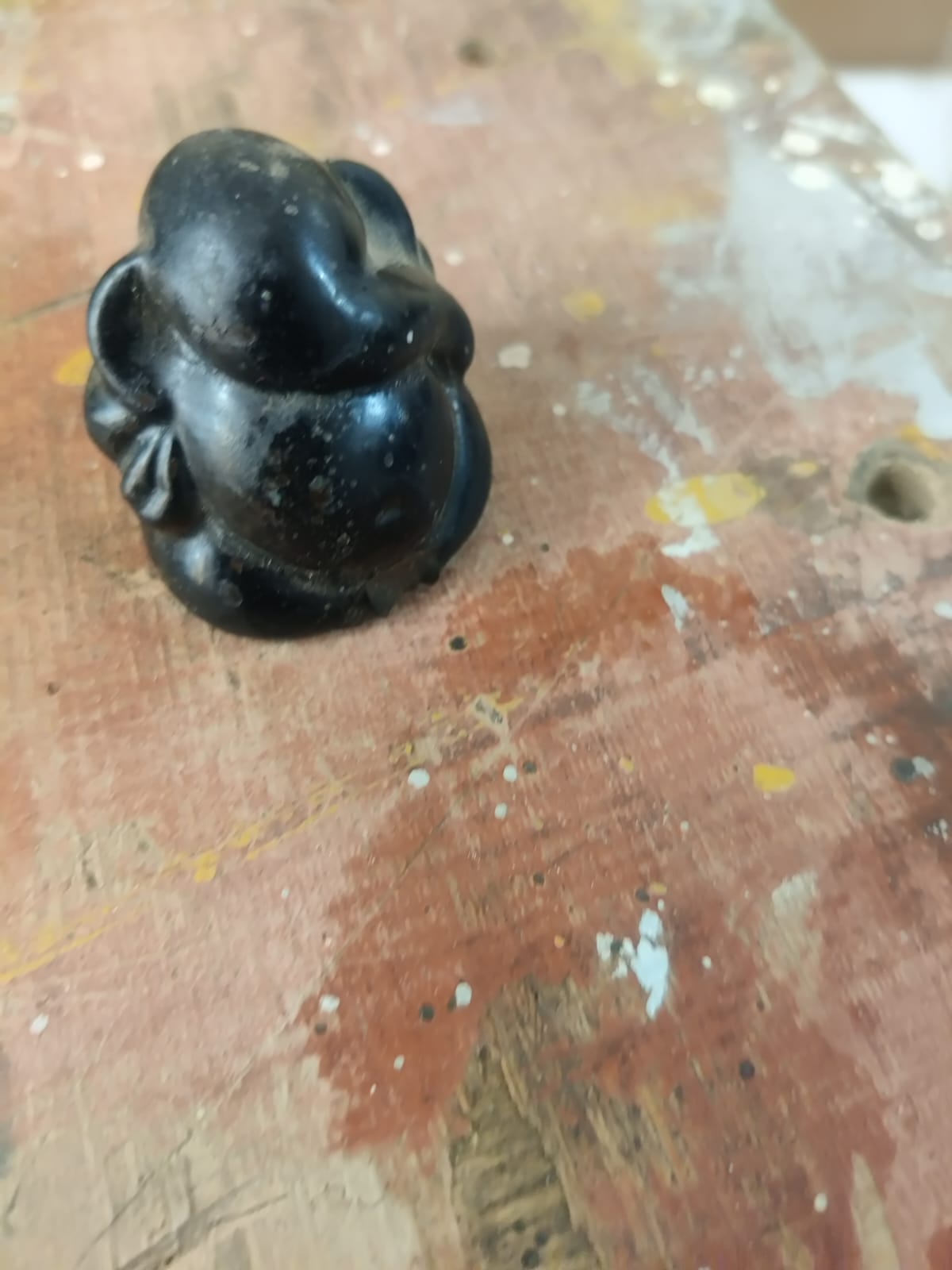
Capture Images
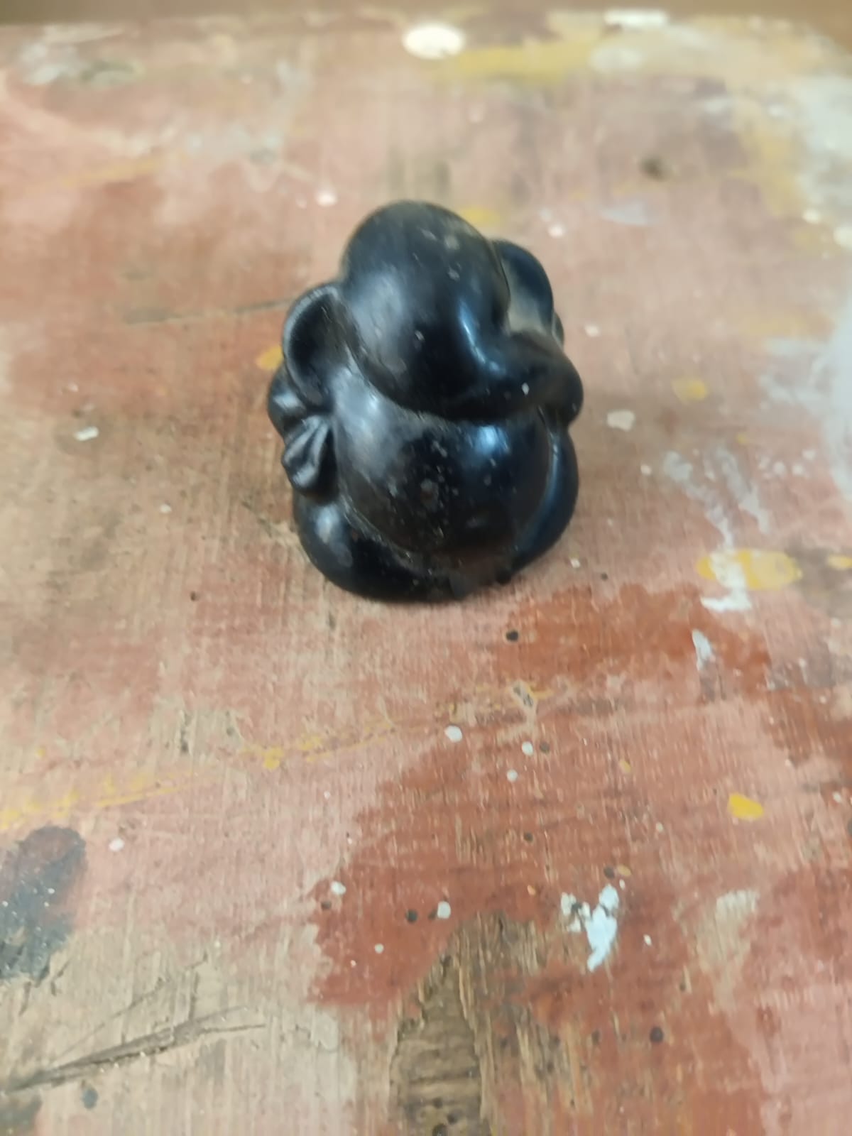
1. Capture Photos of the Object
Begin by placing your object in a well-lit environment with minimal shadows. Use your Android phone to take
40–70 overlapping photos from multiple angles around the object. Move steadily in a circular motion, keeping
the object centered in each frame. Ensure the background has texture (e.g., cloth or paper) to help the app
track orientation.
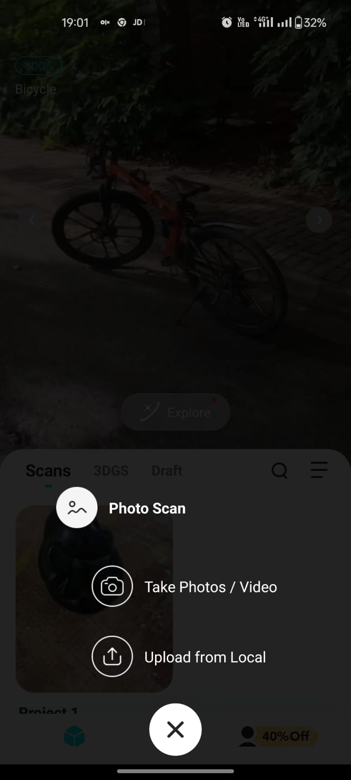
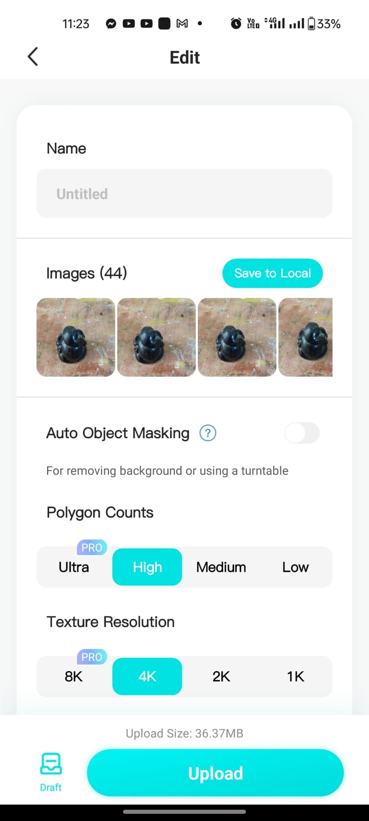
2. Upload to Kiri Engine
Open the Kiri Engine app on your device and start a new scan project. Upload all the
captured photos into the project. You can name the project and select your desired scan settings. Once done,
tap upload, and the images will be sent to Kiri’s cloud servers for processing.
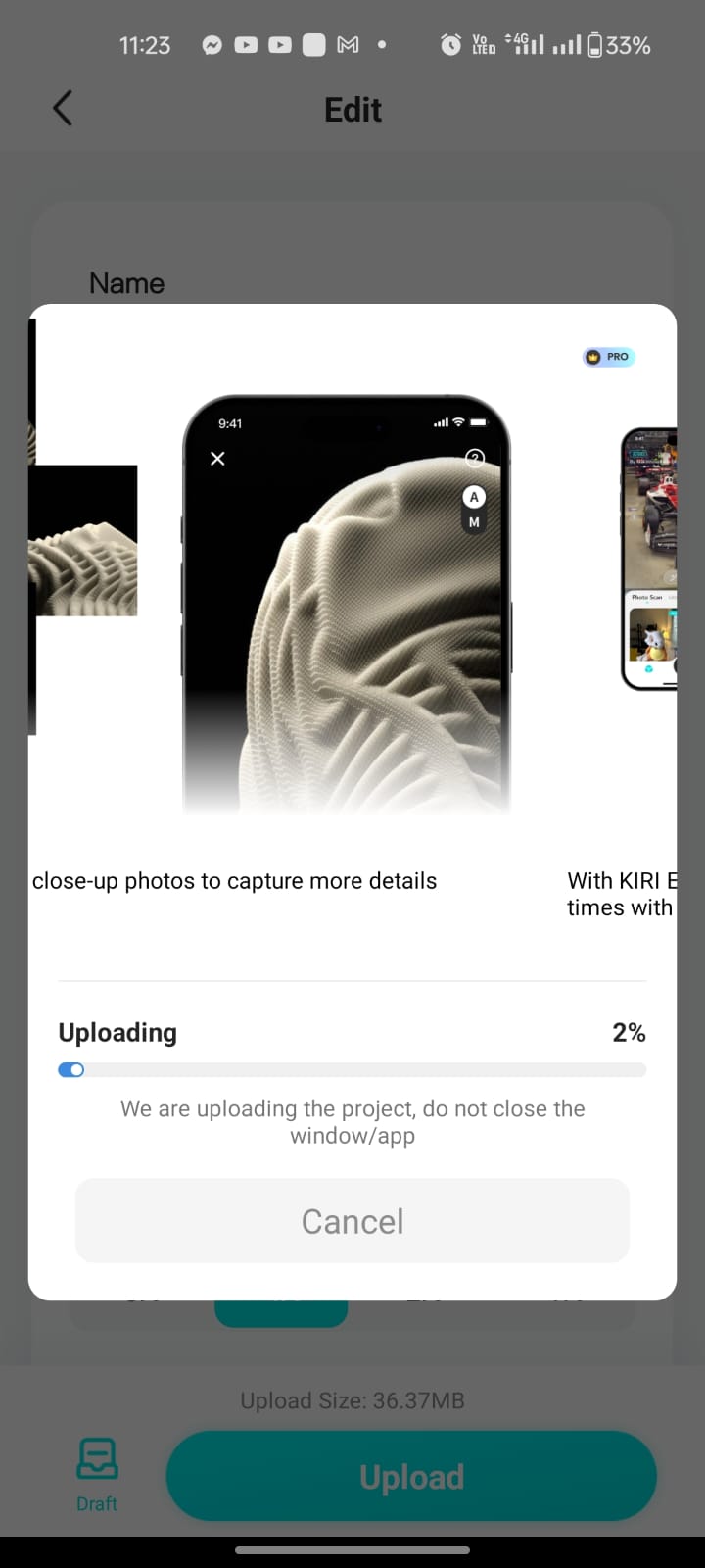
3. Cloud-Based Processing
Kiri Engine performs photogrammetry in the cloud—stitching together the photos to form a 3D mesh. The process typically takes a few minutes. Free users may have to wait longer or face limitations, while Pro users get faster processing and higher resolution outputs. The app notifies you once the model is ready.
4. Review and Edit the Model
Once processed, you can preview the 3D model within the app. Kiri Engine allows you to inspect, rotate, and scale the model. You can also trim unnecessary parts using the cropping tools provided. This step ensures the final model is clean and optimized before export.
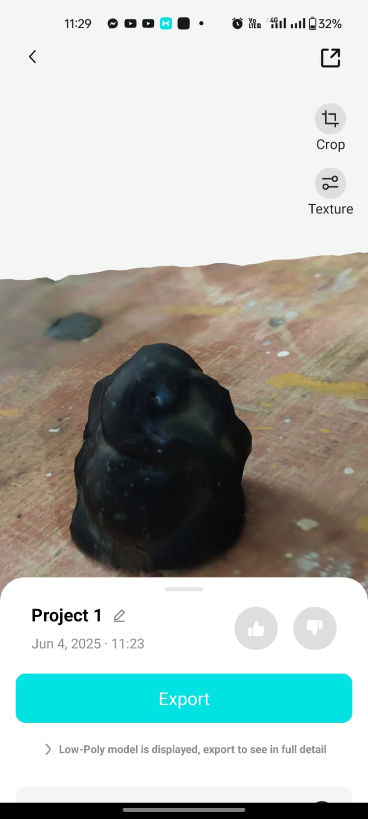
5. Export and Use the 3D Model
After finalizing the model, export it in your preferred format such as STL, OBJ,
or GLB. These formats are compatible with 3D printers, AR platforms, CAD software, or game
engines. You can now use your scanned model for design, prototyping, animation, or digital archiving
purposes.
3D PRINTING
Basics of 3D Printing and its essentials:
Working Principle:
A thermoplastic filament (e.g., PLA, ABS, PETG) is heated and extruded layer by layer to build a 3D object from a digital model (usually in STL or 3MF format).
Each layer is deposited on top of the previous one.
Essential Components:
3D Model (STL, OBJ, or 3MF)
Slicer Software (e.g., FlashPrint, Cura, PrusaSlicer): Converts the 3D model into G-code with toolpath instructions.
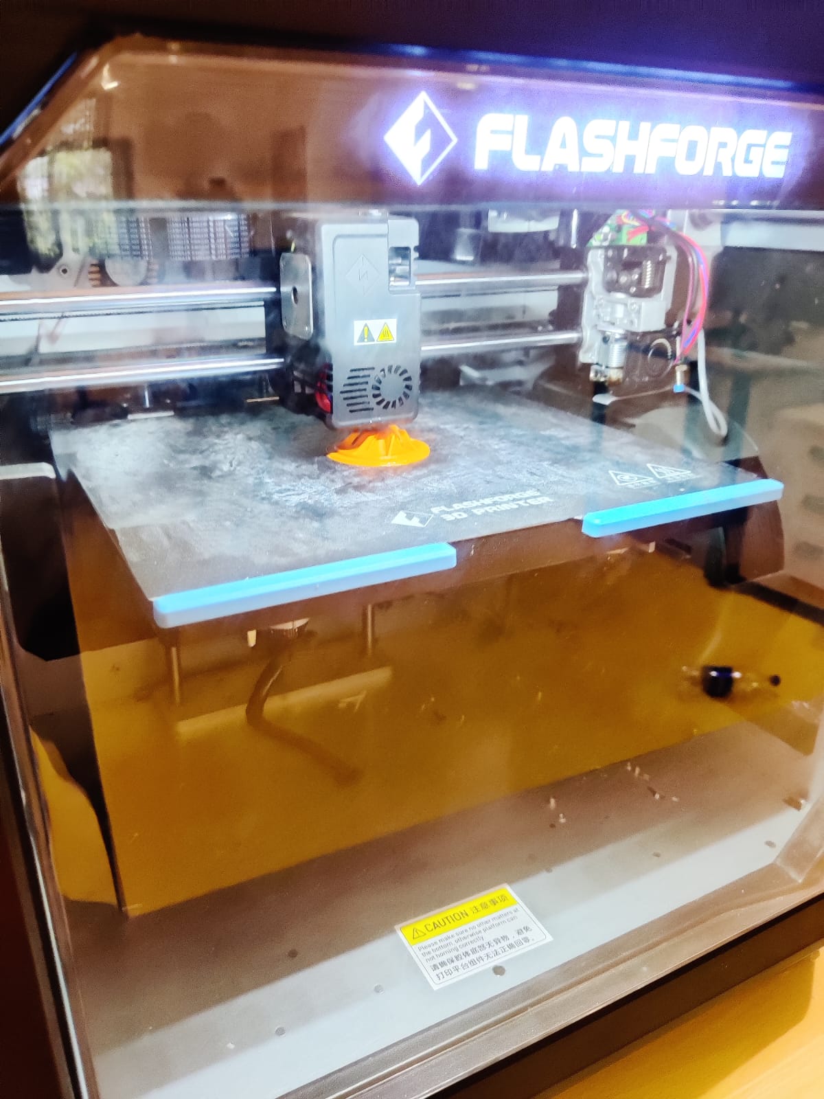
3D Printer ( Flashforge Creator 3 Pro)
Filament: PLA, etc.
Build Plate/Bed: Heated to improve adhesion and prevent warping.
Extruder & Nozzle: Heats and deposits the filament.
Print Settings to Consider:
Layer Height (e.g., 0.1 mm, 0.2 mm): Affects surface finish and print time.
Infill %: Affects strength and weight.
Wall/Perimeter Count: Affects strength of impeller blades.
Supports: Required for overhangs.
Cooling: Especially important for small features like blade edges.
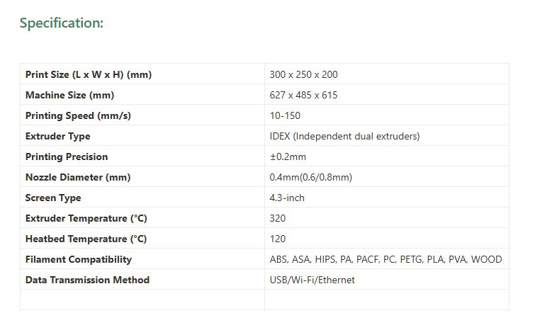
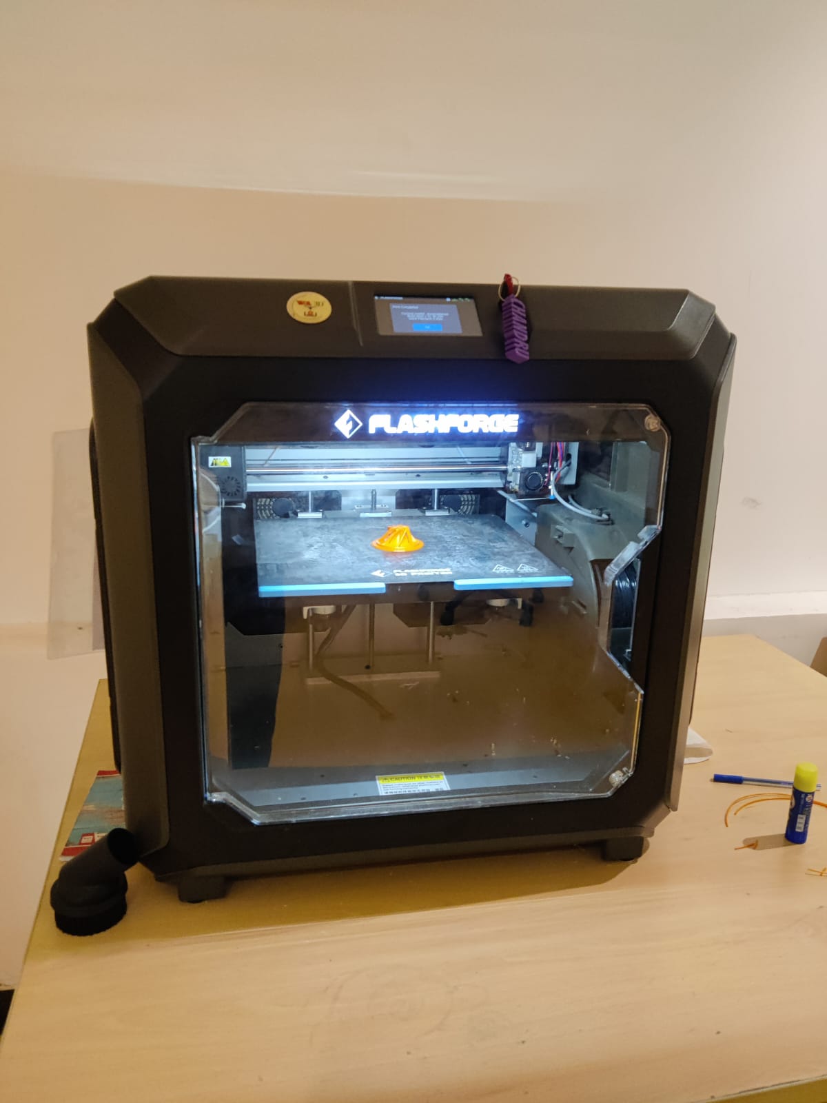
The Flashforge Creator 3 Pro is a updated version of Creator 3 3D printer. The Flashforge Creator 3 Pro is a professional IDEX 3D printer for the needs of small design studios and prototyping firms. IDEX stands for Independent Dual Extrusion which enables it to print two identical objects at the same time. It can also print two colors or materials in one object. Both extruders can reach a very high temp of 320°C, and the bed temperature is up to 120°C. The fully-enclosed build volume is 300 L x 250 W x 200 H mm.
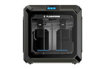
Flashforge Creator 3 Pro – Key Features
Dual Independent Extruders: Allows dual-material or mirror printing
. High Temp Nozzles (up to 320°C): Supports engineering-grade materials.
Heated Bed: Reduces warping in large or complex parts.
Fully Enclosed Chamber: Improves print quality and material control.
Filament Types Supported: PLA, ABS, ASA, PA (Nylon), PC, and more.
Overview. Polylactic Acid, commonly known as PLA, is one of the most popular materials used in desktop 3D printing. It is the default filament of choice for most extrusion-based 3D printers because it can be printed at a low temperature and does not require a heated bed.
Process:
A filament is fed through a heated nozzle, where it melts and is then deposited onto the build plate, solidifying as it cools.
Widely used: Due to its affordability and ease of use, FDM is the most popular 3D printing technology for hobbyists and many professional applications.
Limitations: While versatile, FDM can have visible layer lines and may require support structures for complex geometries.
Step-by-Step: Impeller with Slots in SolidWorks
Start New Part
Open SolidWorks → File > New > Part.
Create Base Sketch (Hub)
Select the Front Plane → Sketch.
Draw a circle ( 50 mm).
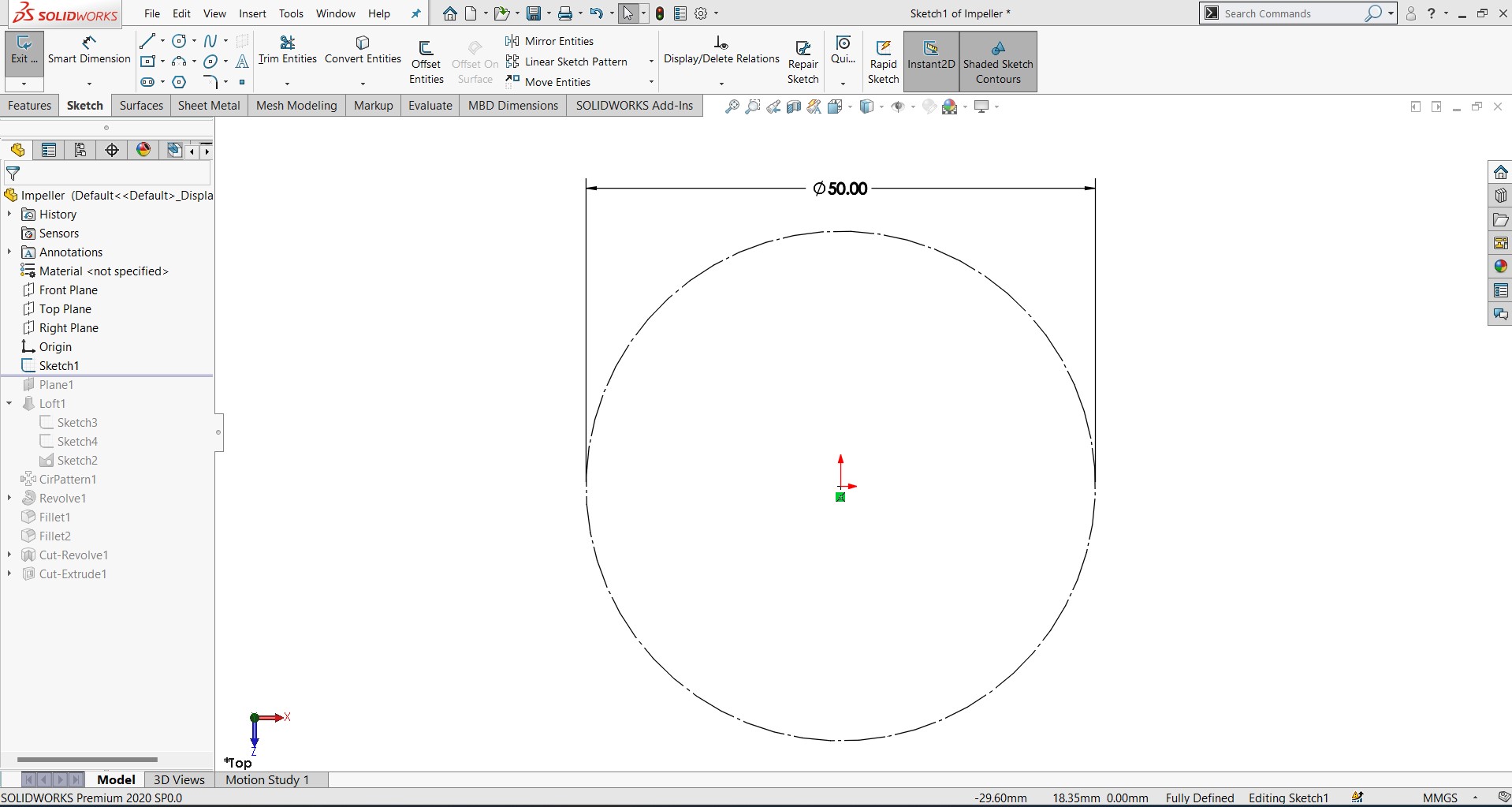
Extrude Base is 2.5 mm thickness arc and its dimension is 25 mm
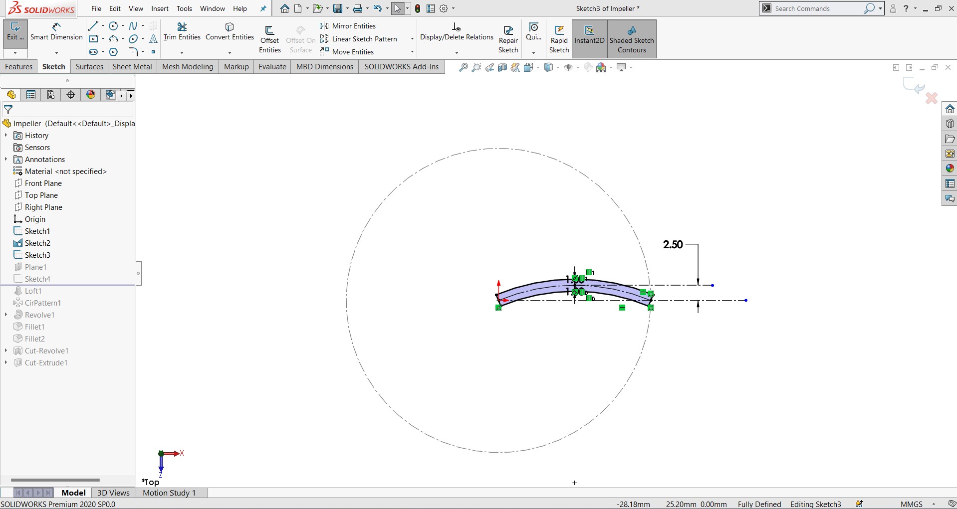
Extrude top is 2. mm thickness it is created like a wedge based on the design for its dimension stablity.
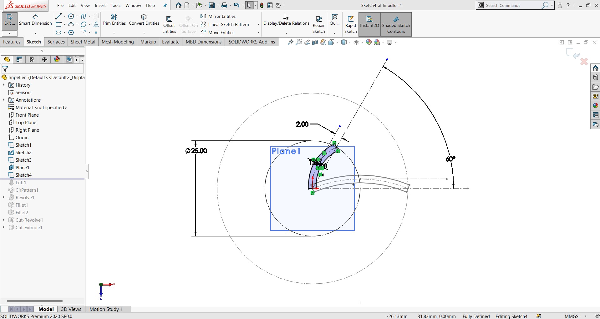
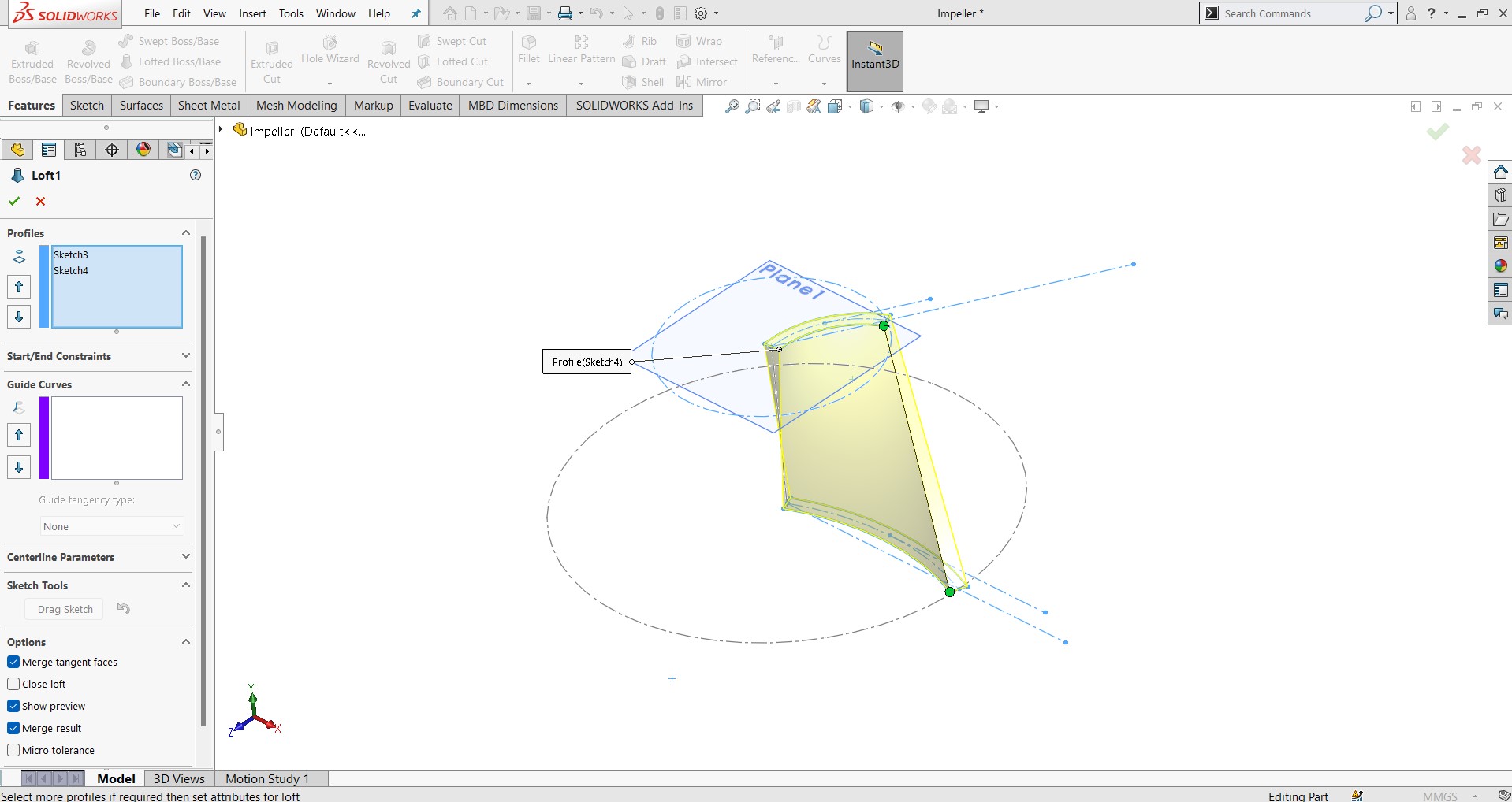
Create a Single Blade
Select the Top face of the hub → Sketch.
Draw the blade shape:
Start from the hub center outward.
Use arcs and lines to form a curved airfoil.
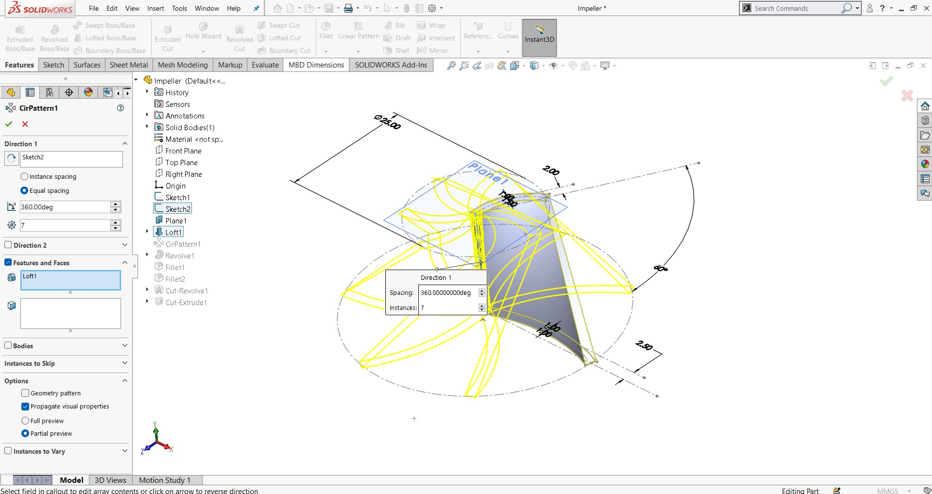
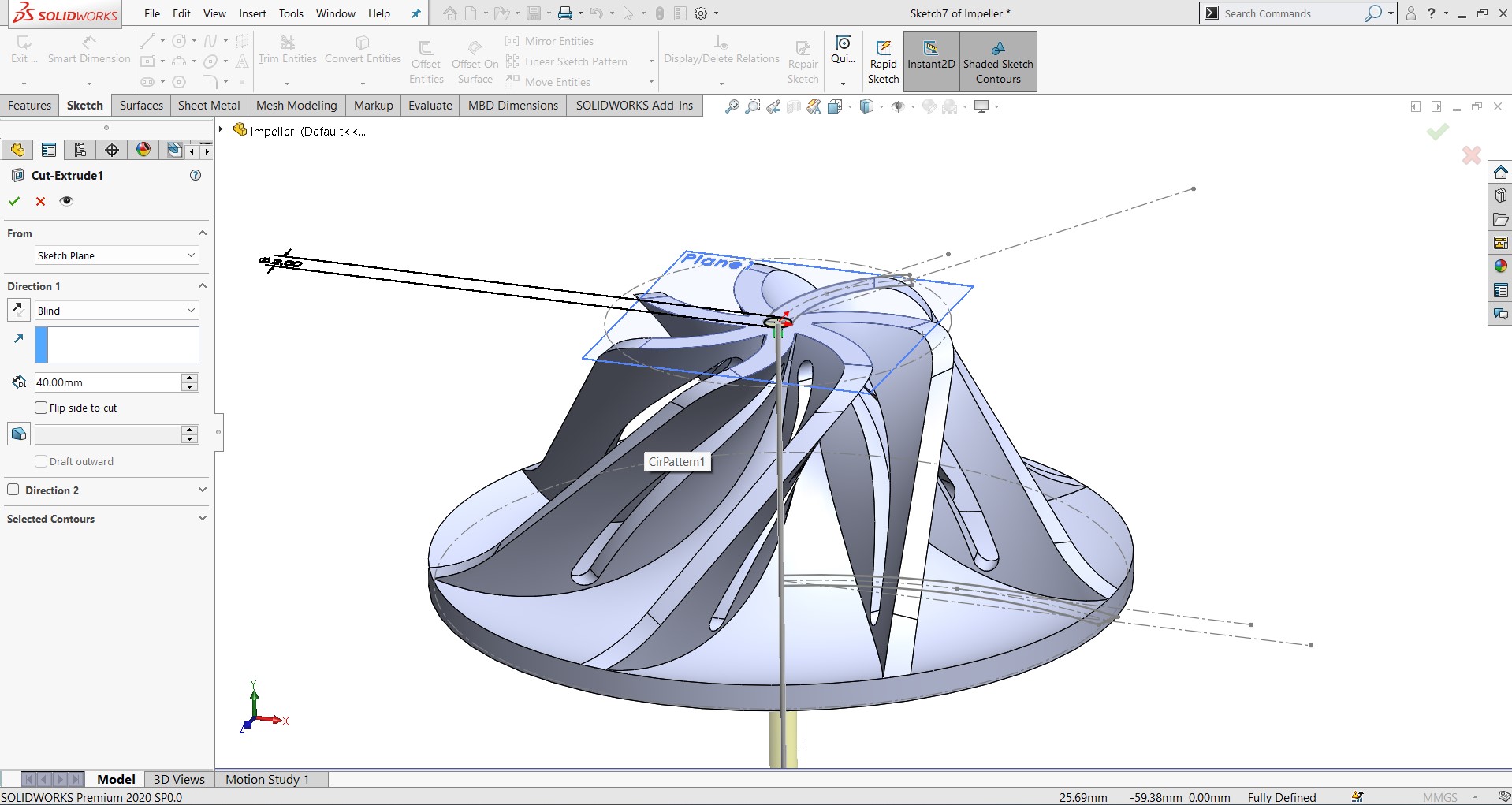
Create Circular Pattern
Go to Features → Circular Pattern.
Select the blade
Select the hub's center axis as the axis of rotation.
Enter the number of blades 7 and spacing 36 degree.
Confirm to replicate all blades .
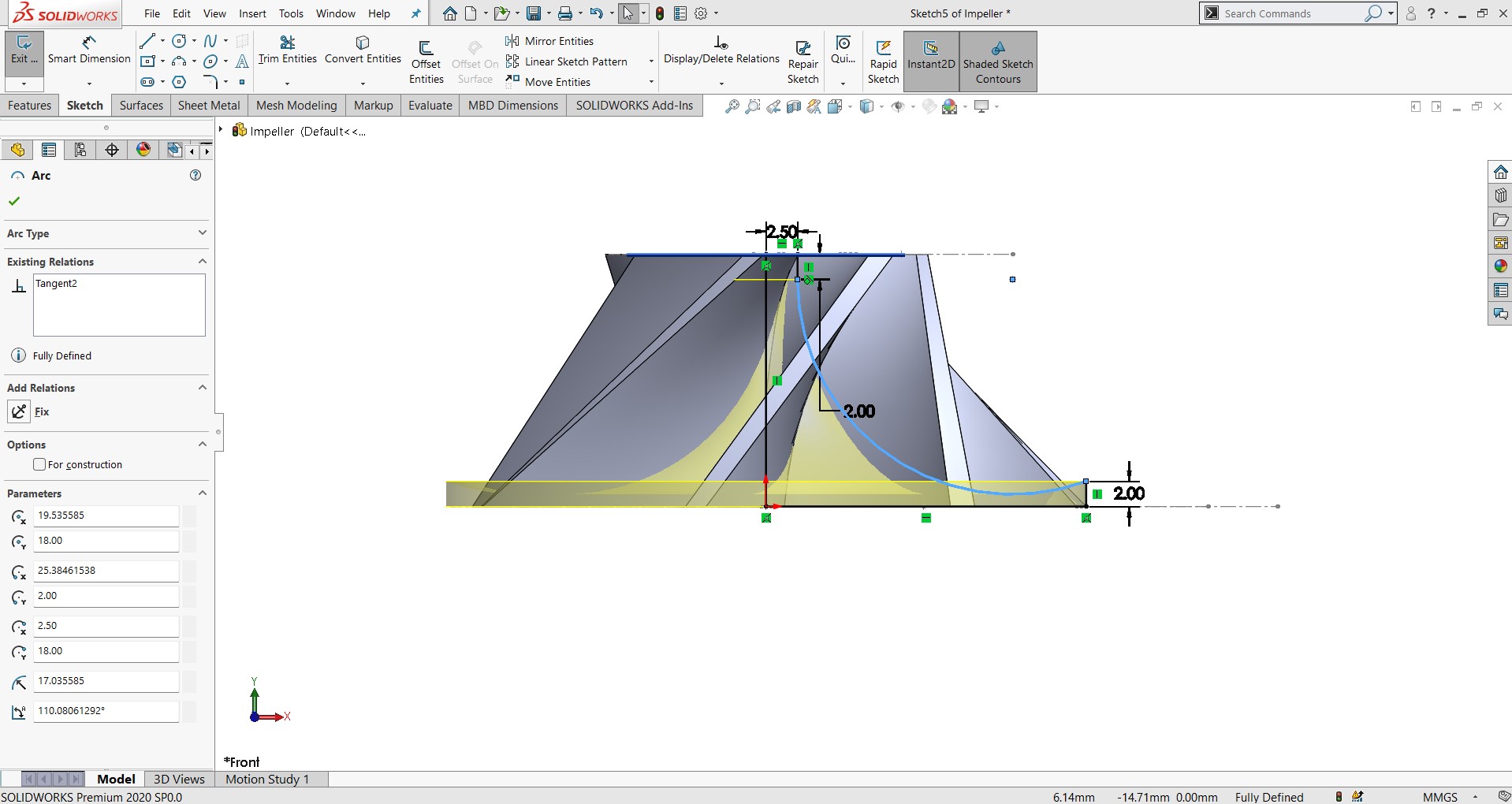
round is 20 mm dia and extude total height is 18 mm
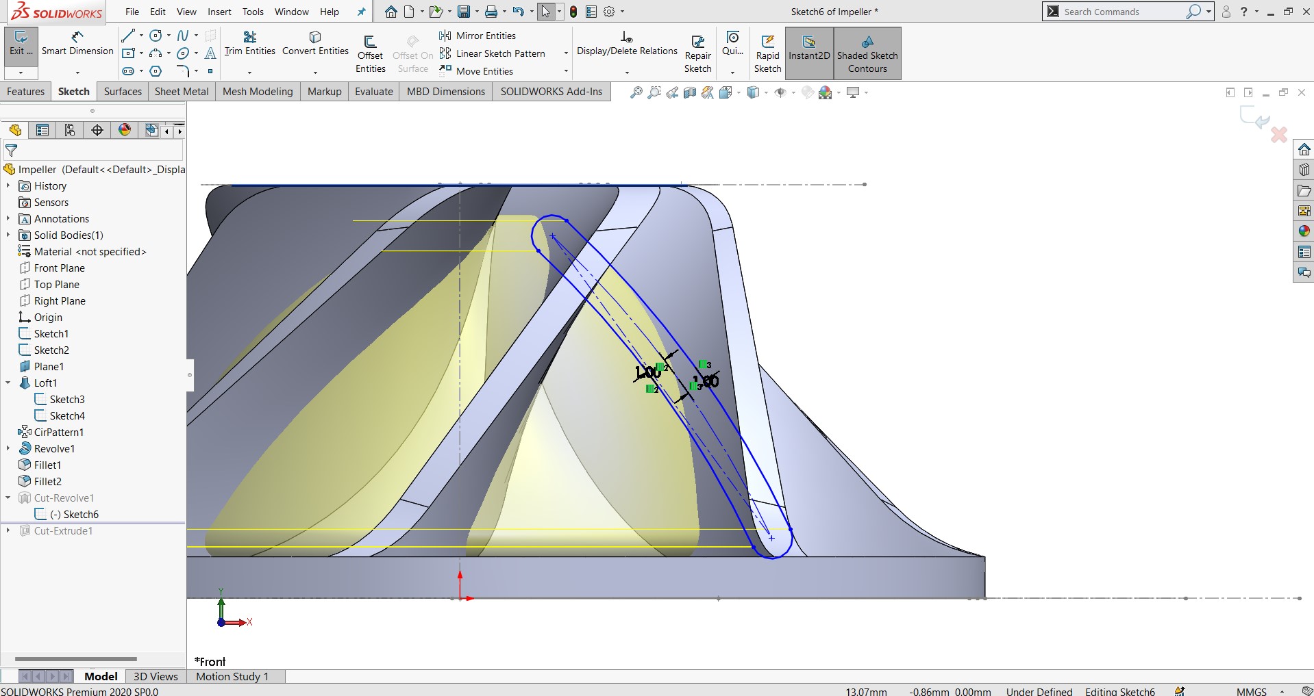
Add Slot to Blade
Select the side face of the blade → Sketch.
Draw a 10 mm slot (rectangle or slot tool).
Use Cut Extrude to make a hole through the blade.
Add Central Hole
Select Top face of hub → Sketch.
Draw and Cut Extrude a center hole for a shaft 2 mm
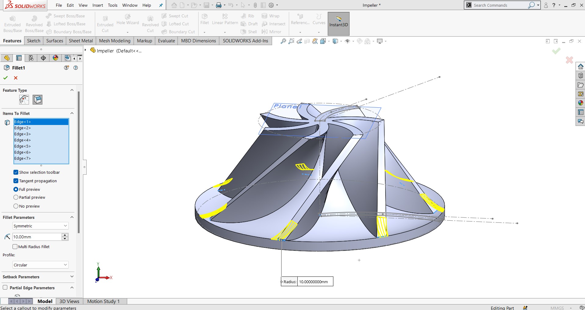
Final Touches
Add fillets to blade edges if needed.
Apply materials (e.g., ABS plastic).
Use Evaluate > Mass Properties for weight check.
Save and Export
File > Save As → SolidWorks part (.SLDPRT).
For 3D printing: File > Save As > STL (*.stl).
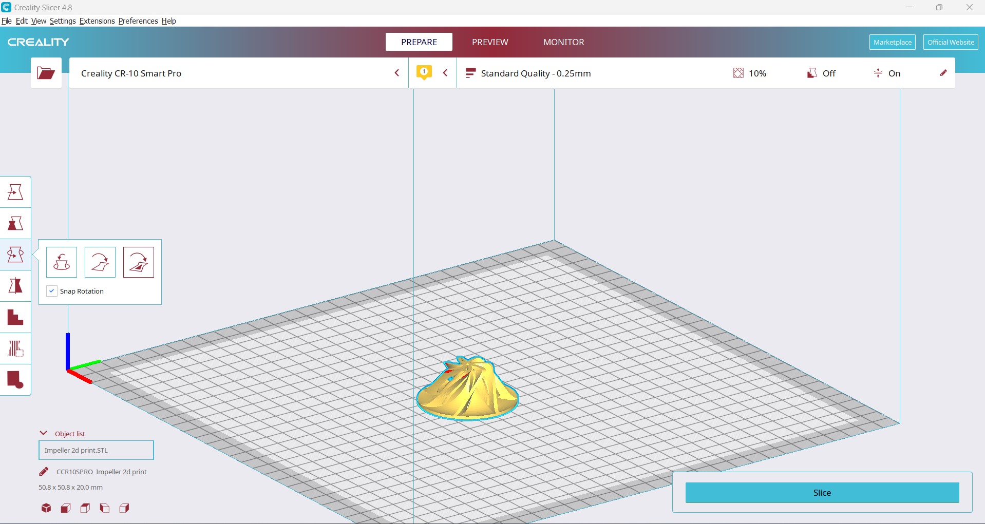
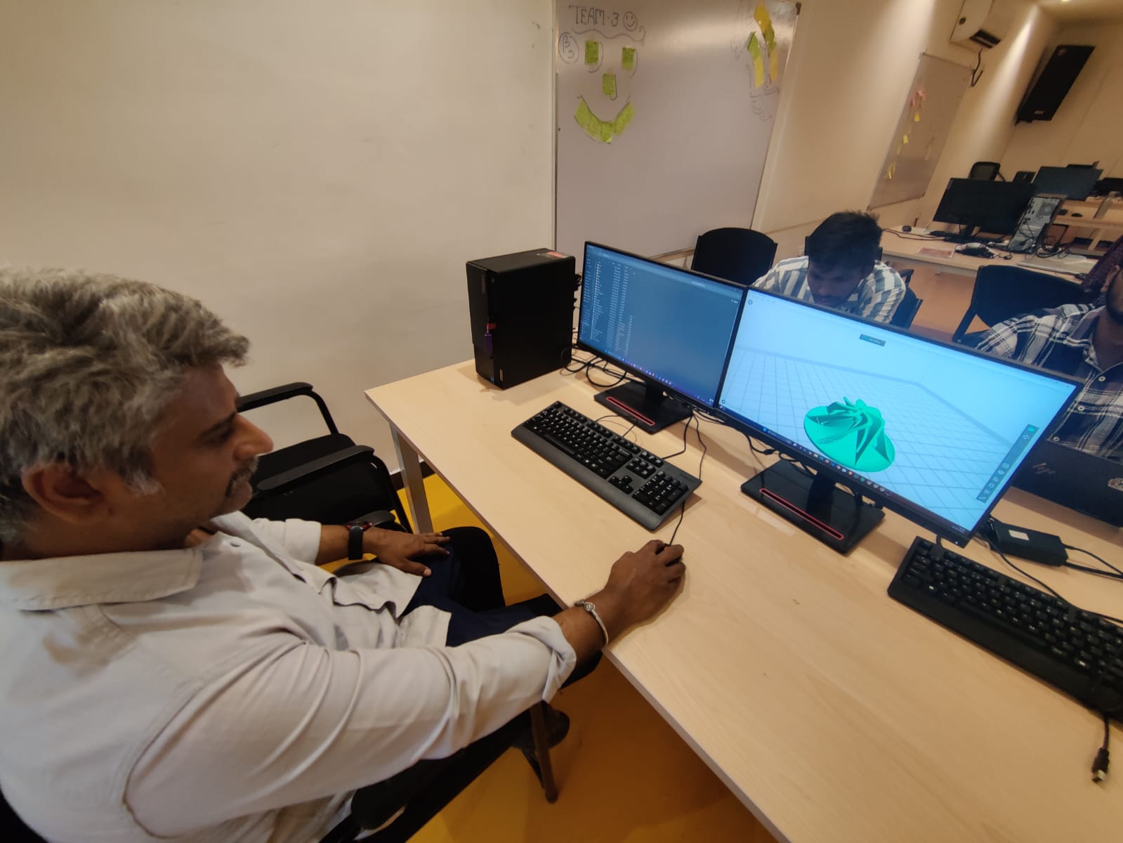
Import into Slicer Creality Print
You can use:
Creality Print
recommended, with Creality profile
Set Printer to Creality CR-10 Smart Pro.
Drag and drop the STL file into the workspace.
Adjust:
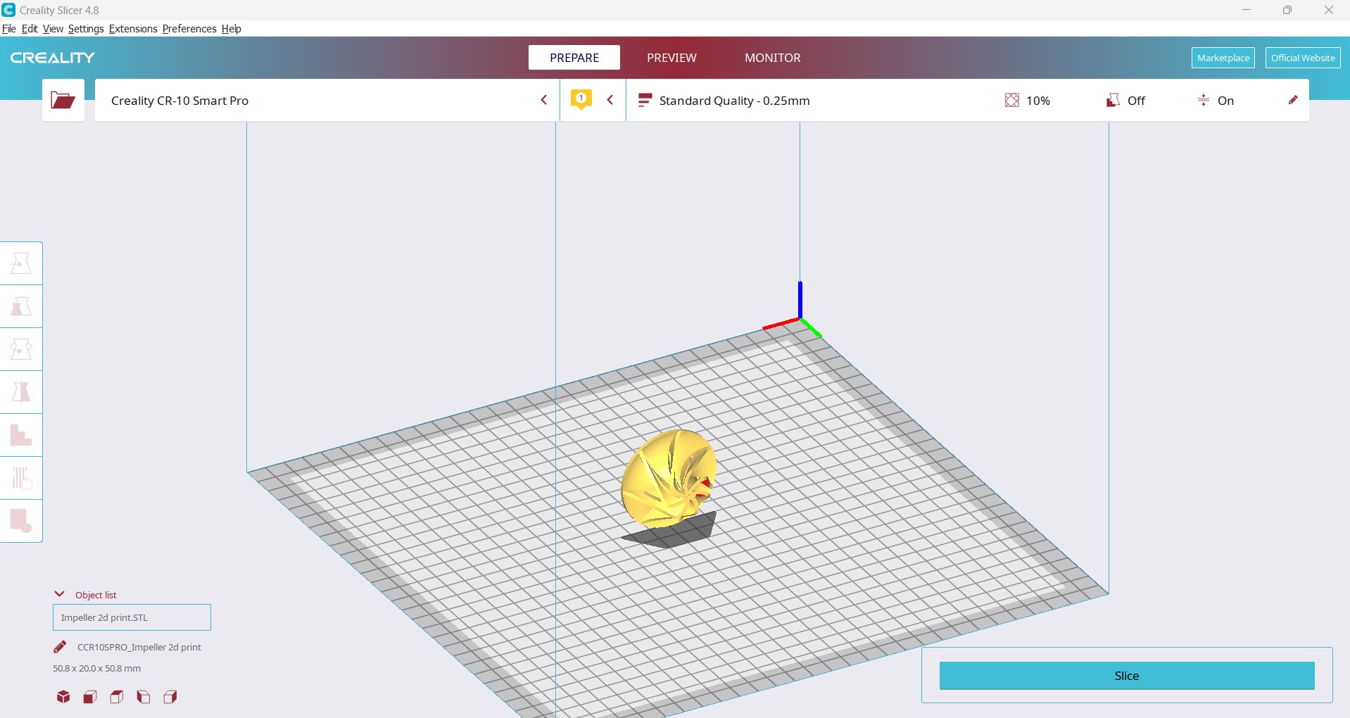
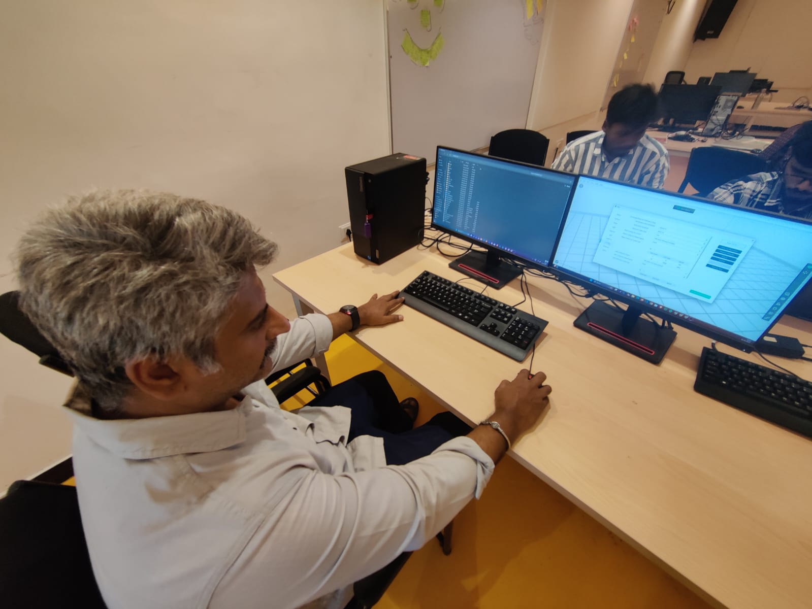
Slice the Model
Click Slice.
Review estimated time and material use.
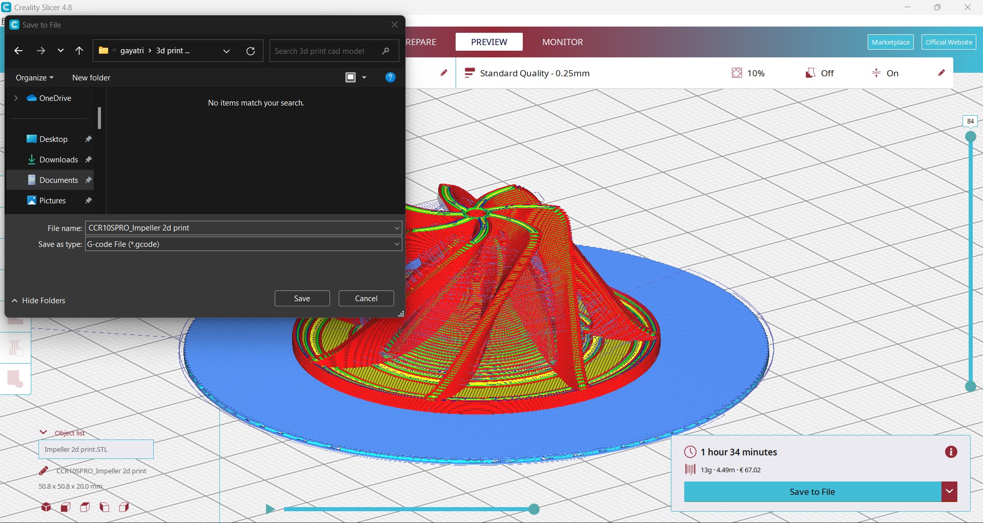
Click Save to Disk or Save to Removable Drive (for SD card/USB).
Import into Slicer Creality Print
You can use:
Creality Print
recommended, with Creality profile
Set Printer to Creality CR-10 Smart Pro.
Drag and drop the STL file into the workspace.
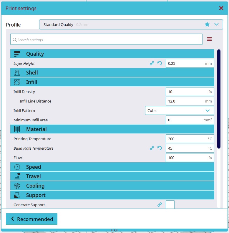
Adjust:
Orientation: Flat side of the hub on the bed.
Scale: If needed.
Supports: Enable for overhangs between blades.
Infill: 40–60% for strength (higher if impeller is functional).
Wall/Perimeter: At least 3 lines for strong blades.
Layer Height: 0.2 mm (or 0.1 mm for better detail).
Material Preset: Choose PLA, PETG, or desired filament.
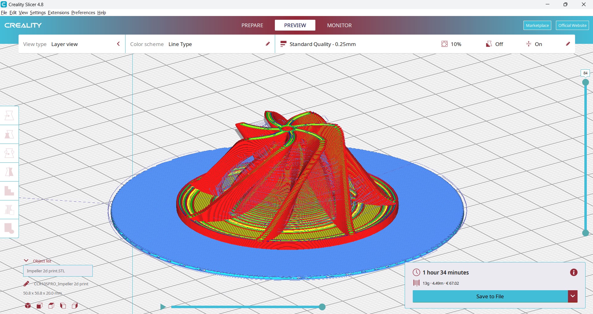
Slice the Model
Click Slice.
Review estimated time and material use.
Click Save to Disk or Save to Removable Drive (for SD card/USB).
Power on the Creality CR-10 Smart Pro.
Insert the USB stick.
Load filament PLA
Heat nozzle to 200–220°C . Insert filament until it flows cleanly.
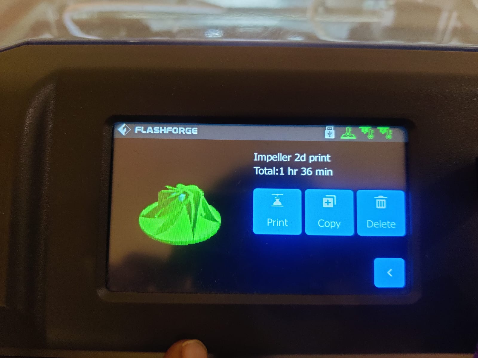
Start the Print On the touchscreen: Print > Select File >print
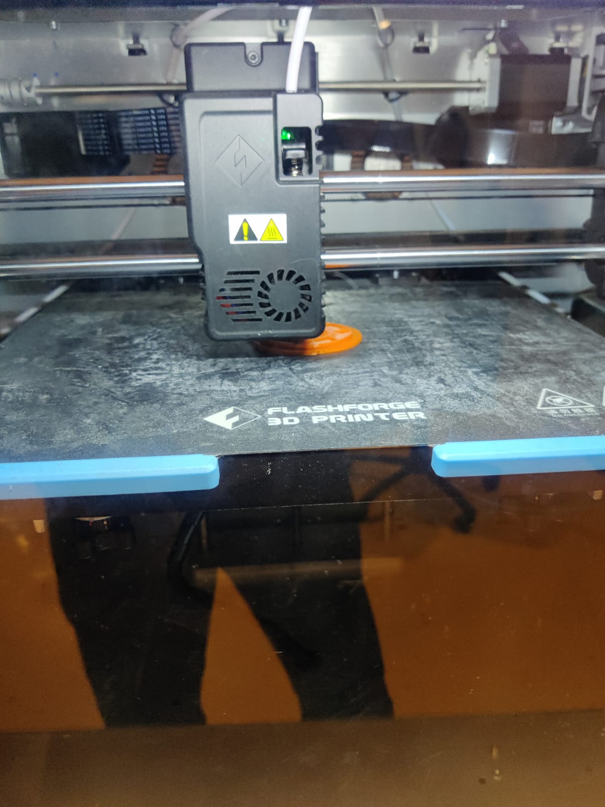
check filament is feeding smoothly:
No grinding/slipping
Consistent extrusion
Look at the extruder gear for any filament chewing or skipping.
 |
 |
Confirm:
Nozzle temp matches material (e.g., PLA: ~200°C, PETG: ~240°C)
Bed temp is appropriate (e.g., PLA: ~60°C)
Make sure the temps are stable and not fluctuating.
Ensure support structures are forming well if enabled.
Watch for drooping overhangs.
Check every 10 mins carfully.
 |
 |
 |
 |
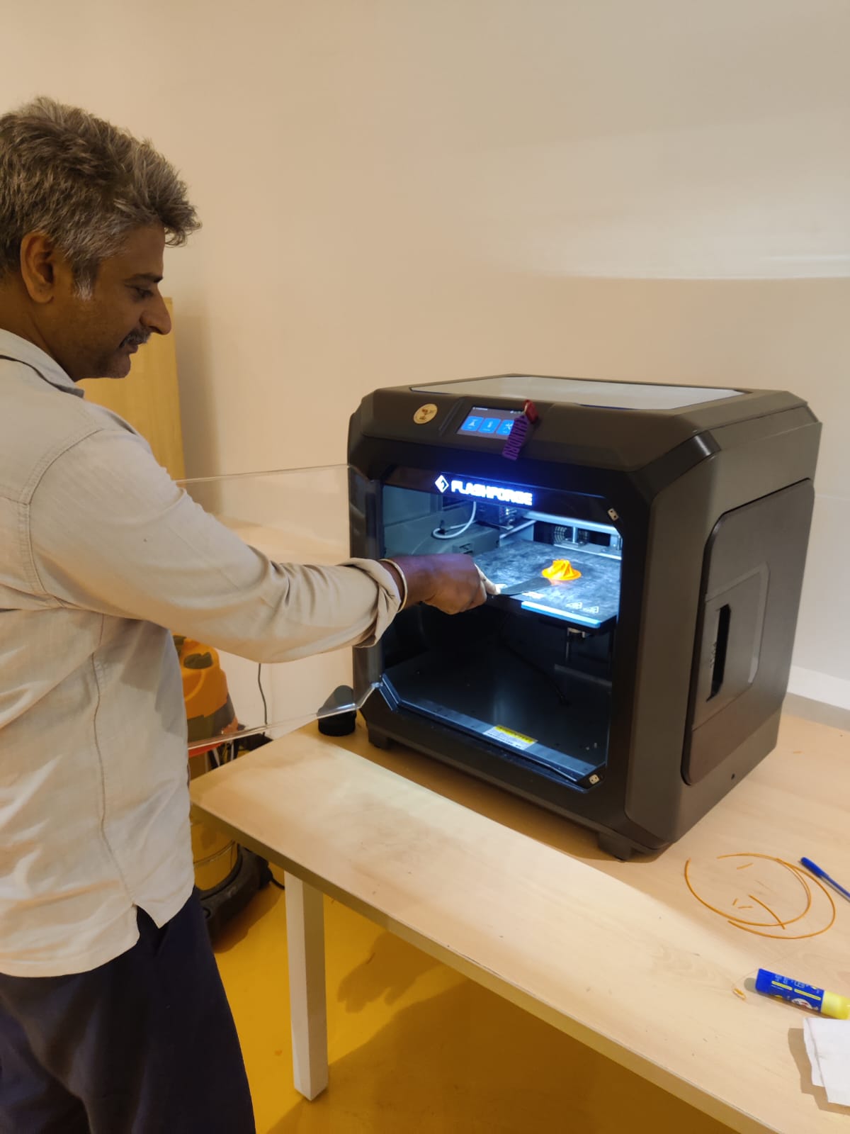
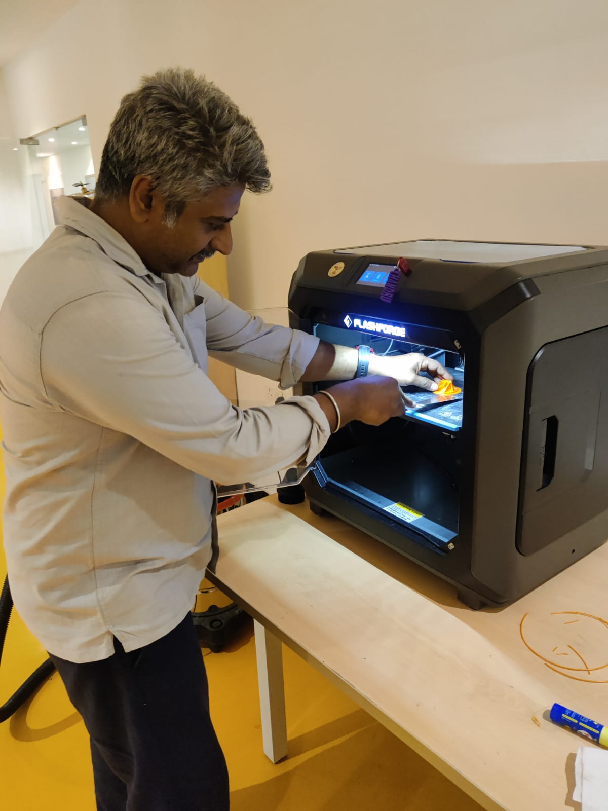
Let It Cool First
Wait 15 minutes after the print finishes.
As the bed and part cool, the material contracts slightly, making removal easier.
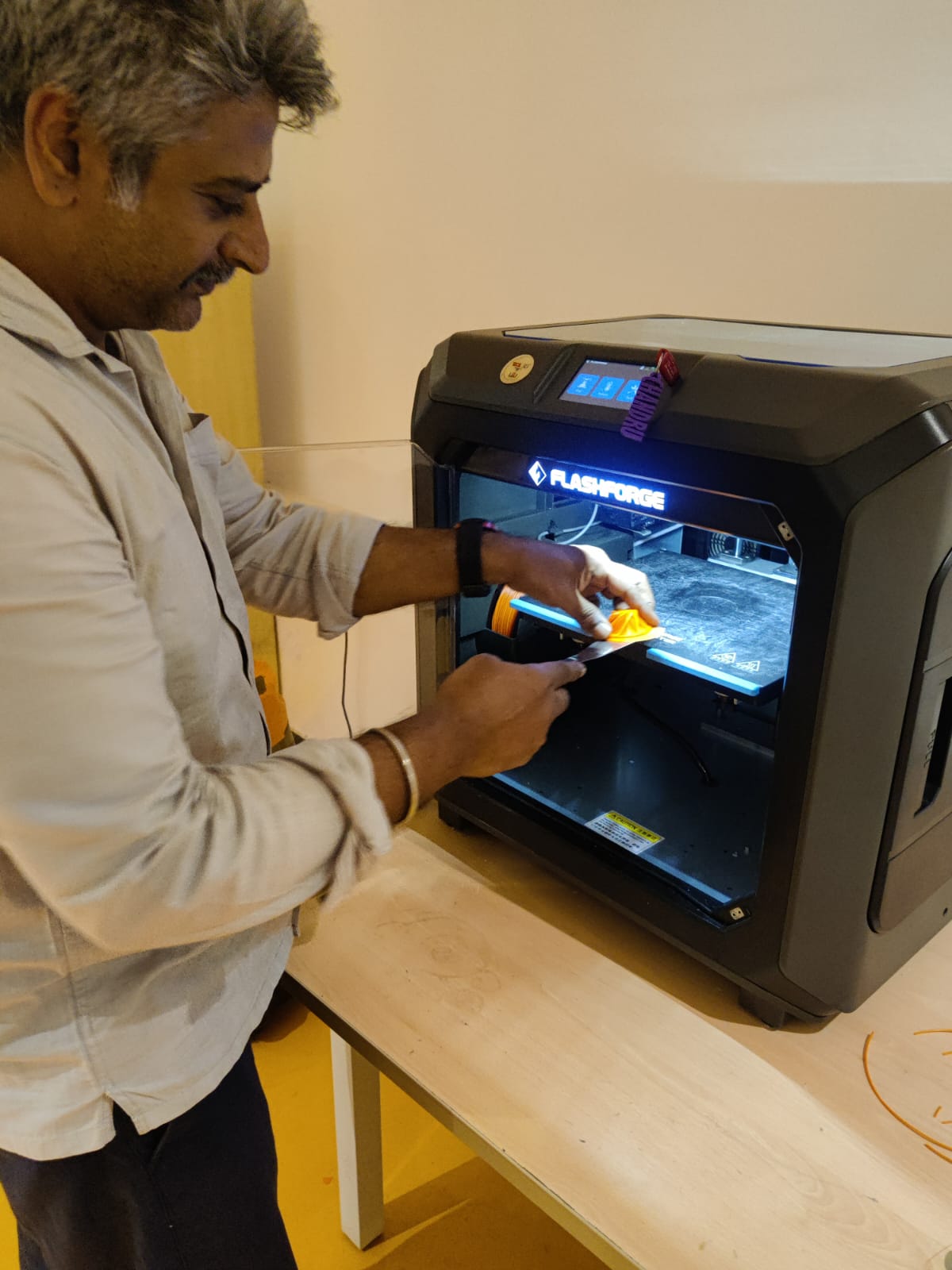
Use the flat edge of the tool to slide under one corner of the print.
Gently wiggle or twist — avoid forceful prying.
Insert deeper gradually along the edge until the part lifts.
Loosen from Corners, Not Center
Start from the corners or edges, not the middle of the part.
This reduces the chance of cracking or snapping thin features.
Warm the bed slightly (e.g., reheat to 40–50°C).
Use isopropyl alcohol (IPA) around the base to loosen adhesion (if using glue stick or PEI sheet).
Clean the print bed surface with IPA and a lint-free cloth.
Check the part for leftover support material or raft and remove it safely with pliers or flush cutters.
 |
 |
 |
|
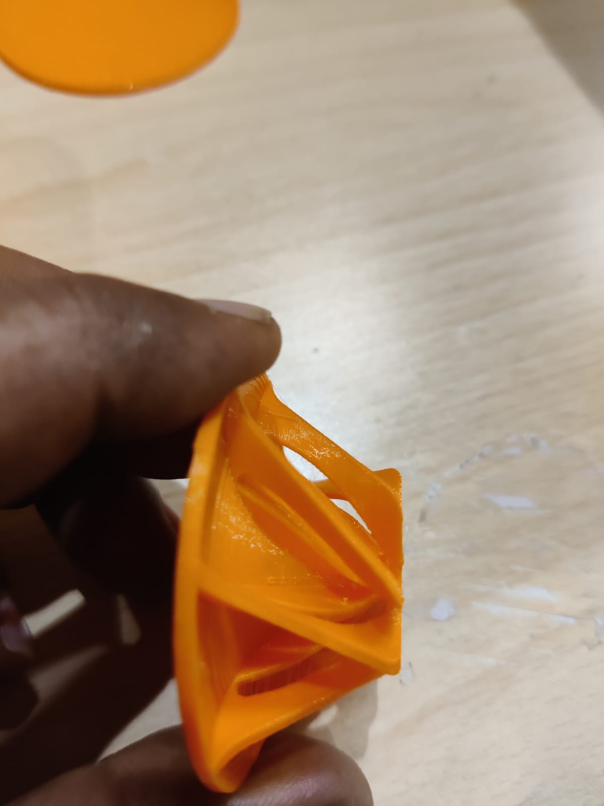
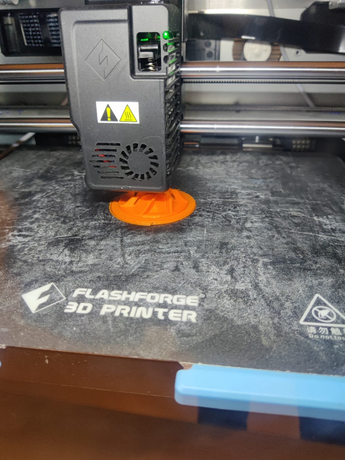
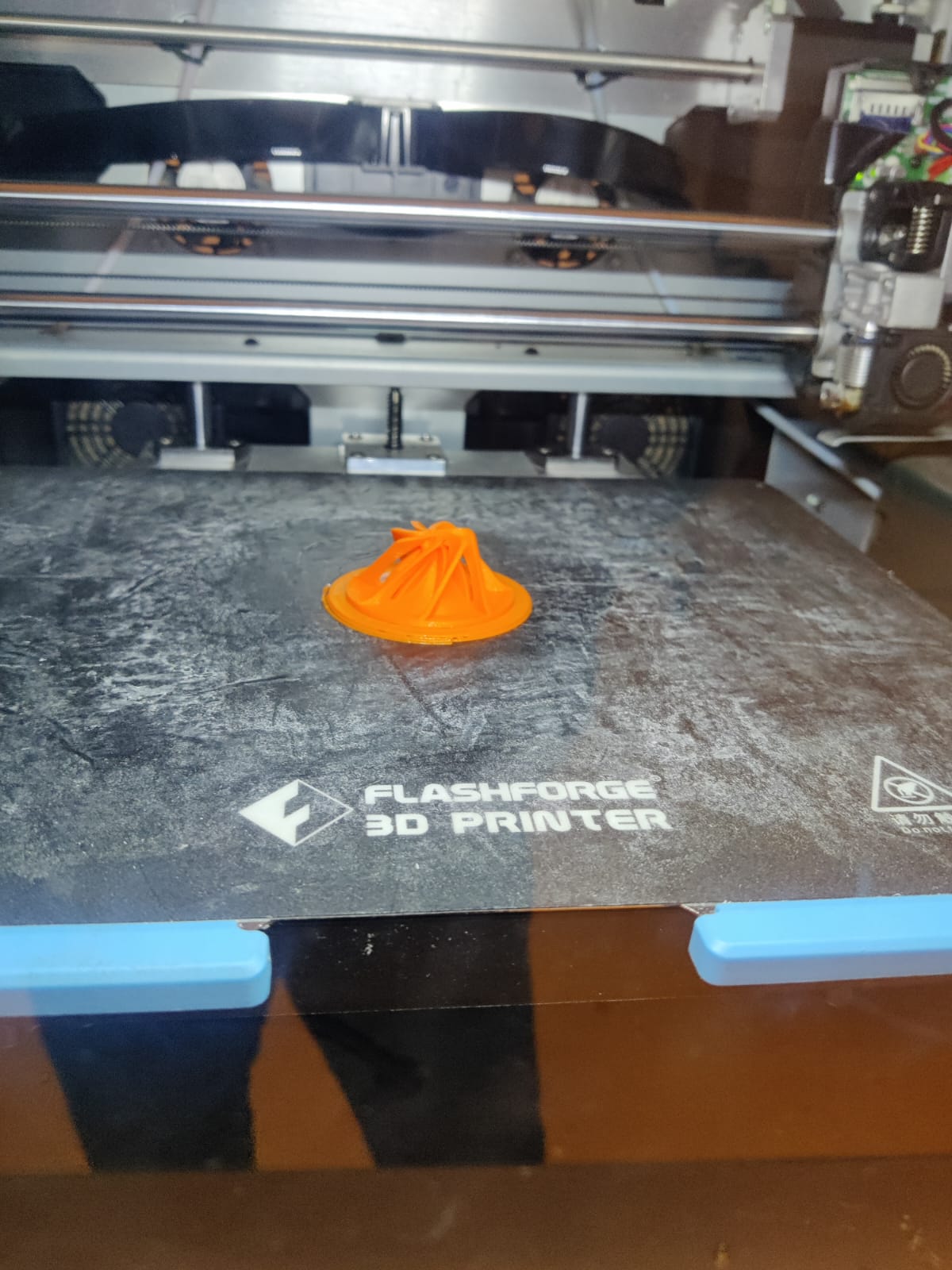
The printed impeller is very clear, with sharp edges and smooth surfaces. All blade slots are accurately formed, and no warping or defects are visible. Support material was easy to remove. The part fits perfectly and is ready to use without any post-processing. A successful, high-quality print from start to finish..
why your design could not be easily made subtractively?
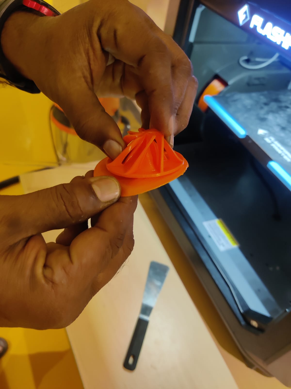
Impeller Blade Design Feature
Vertically from top to bottom, there is an open cut in every blade of the impeller, designed to enhance fluid dynamics and reduce resistance. This slot-like opening allows the fluid or air to pass more efficiently along the blade surface, reducing backpressure and improving overall performance.
However, this feature cannot be manufactured using subtractive methods like milling or turning due to its complex internal geometry and orientation. The vertical cuts often include undercuts or follow curved paths that are inaccessible to conventional cutting tools.
Therefore, this design is best realized using additive manufacturing, allowing the impeller to be built layer by layer with high precision and internal complexity.
Reference Files
3d printing Stl file
Impeller 3d print.STL
3dscanned gip file.