Group assignment:
Group Assignment Summary
As part of the group assignment, we explored and compared different embedded architectures, microcontrollers, programming toolchains, and development workflows. We programmed and tested boards from different microcontroller families using their respective programming methods and development environments. This comparison helped us understand the differences between AVR, ARM, and ESP-based architectures, along with various programming interfaces such as ISP, UPDI, JTAG/SWD, and USB-Serial. We also evaluated the advantages, limitations, and workflows of different embedded platforms, gaining practical experience in programming, uploading firmware, and debugging embedded systems. This activity provided a strong foundation for selecting suitable microcontrollers and development environments for future projects.
1.Demonstrate and compare the toolchains and development workflows for available embedded architectures 2.Document your work to the group work page and reflect on your individual page what you learned
Individual assignment:
"HERO SHOT"
1.Browse through the datasheet for your microcontroller.
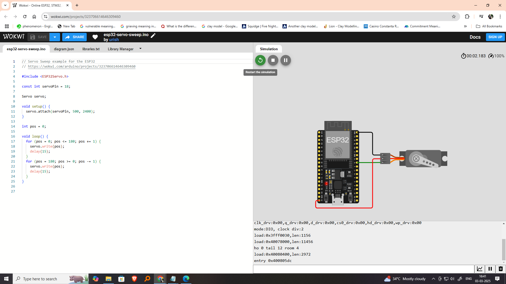
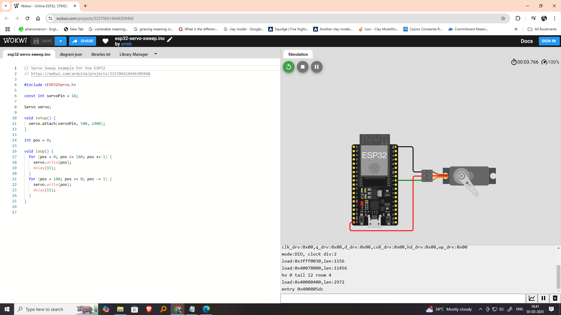
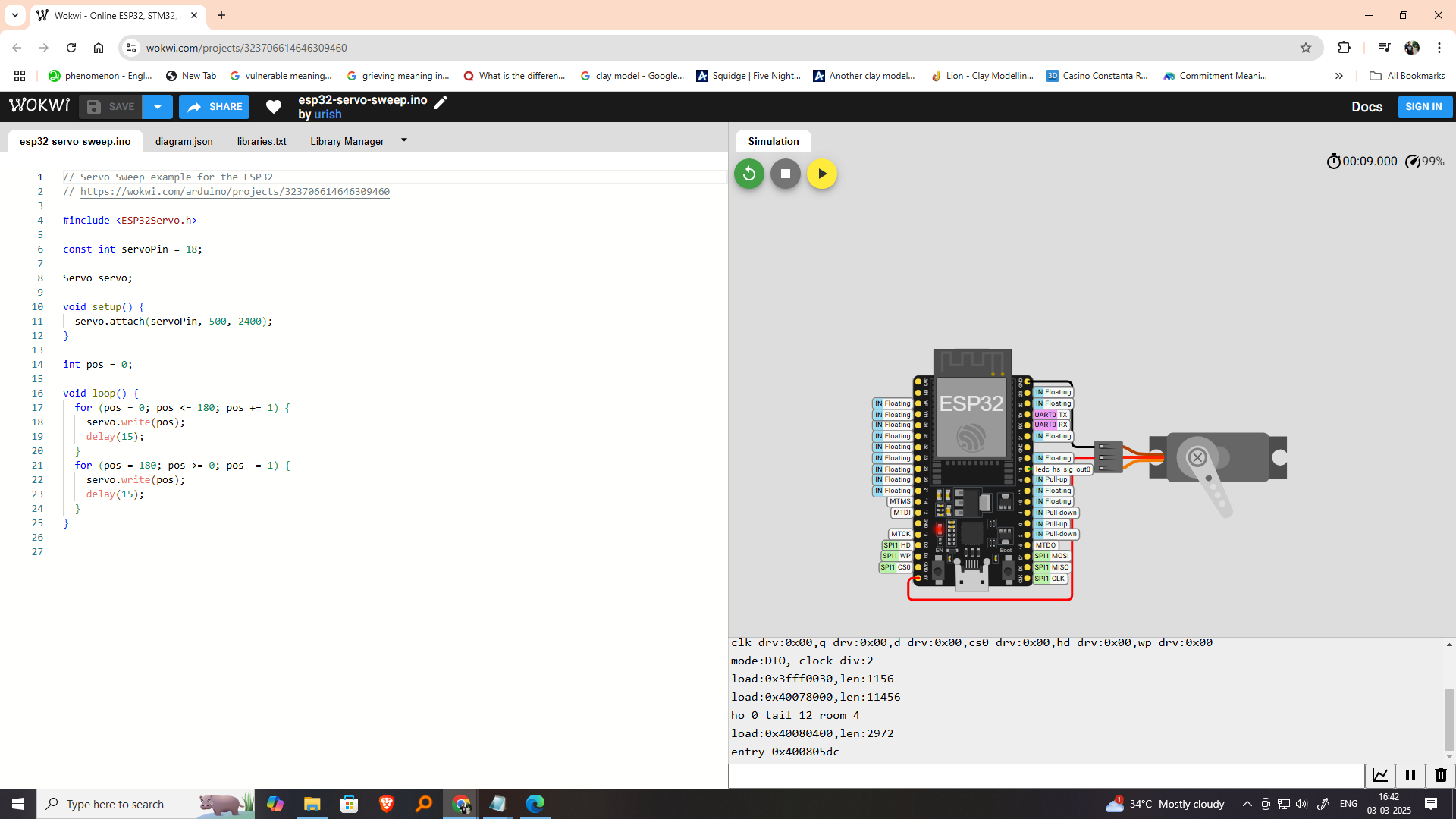
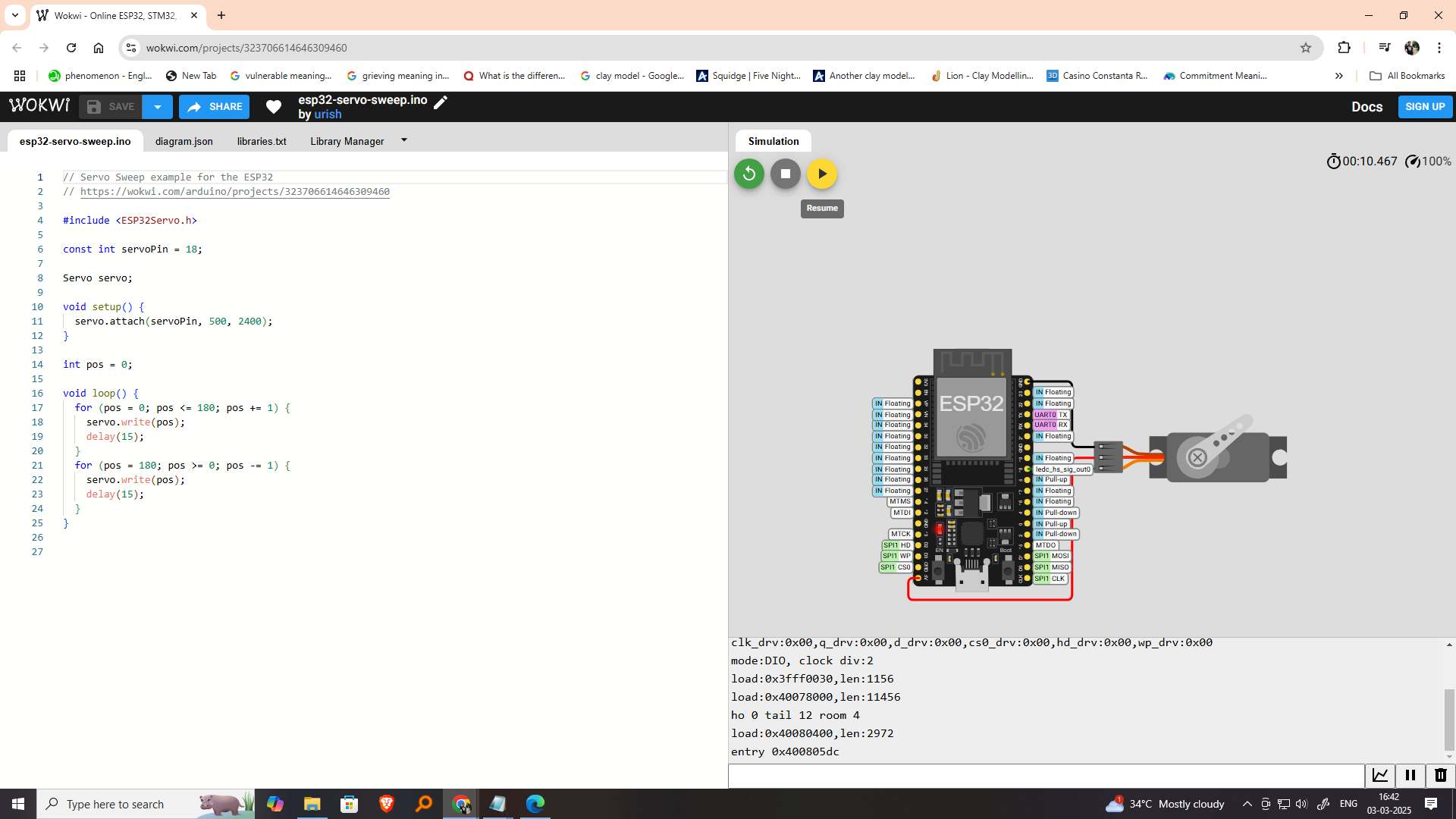
2. Write a program for a microcontroller, and simulate its operation, to interact (with local input &/or output
devices) and communicate (with remote wired or wireless
connection)
3.Learning outcomes
To make things quick and easy for you, we have split all the boards into three main categories, Entry Level Arduino boards, Enhanced Arduino boards, and IoT Arduino boards. Further, we have also provided a table under each section for quick skimming, so let’s get started.
Entry-Level Arduino Boards
These types of Arduino boards are the best choice to start with. In this category, most boards have either slow clock speed or a limited number of I/O ports. All these boards are powered by 8-bit microcontrollers. Most of them are easy to learn and make projects with. Not only that, there are a variety of modules and shield boards available on the market, especially targeting these base-level boards. Here is the table showing all the features of these boards.
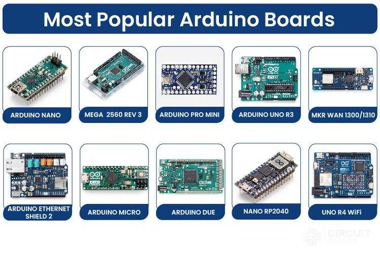
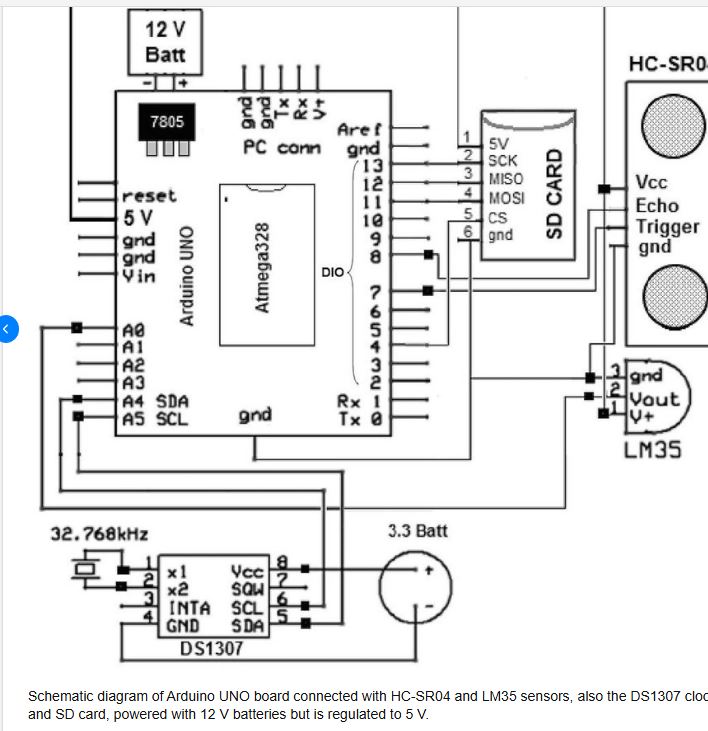
Arduino Uno is the most popular and widely used development board. It is powered by an ATMega328P microcontroller. It is the most popular choice among the community because it’s, cheap, easy to learn and use, and also a variety of premade modules are available for this which makes it easier for developing new projects or prototypes. It consists of 14 Digital I/O out of which 6 pins are 8bit PWM pins, 6 pins are 10-bit Analog inputs, and basic communication ports like SPI, I2C, and UART.
Now, there are many different types of Arduino UNO boards available across the global market, but most of these boards are the clone or copy versions of the original UNO board that you see above. Hence the color or the appearance of the board might be different than what is shown above.
Arduino Uno Overview
Microcontroller: ATmega328P
Operating Voltage: 5V
Input Voltage (recommended): 7–12V
Input Voltage (limits): 6–20V
Digital I/O Pins: 14 (of which 6 provide PWM output)
Analog Input Pins: 6
DC Current per I/O Pin: 20 mA
Flash Memory: 32 KB (ATmega328P) – 0.5 KB used by bootloader
SRAM: 2 KB
EEPROM: 1 KB
Clock Speed: 16 MHz
USB Connection: Type-B
Power Jack: Barrel jack
ICSP Header: Yes
Reset Button: Yes
Arduino Uno Pinout
Digital Pins (0–13)
| Pin | Function |
|---|---|
| 0 | RX (Serial Receive) |
| 1 | TX (Serial Transmit) |
| 2–13 | General I/O |
| 3, 5, 6, 9, 10, 11 | PWM Output (AnalogWrite) |
Analog Pins (A0–A5)
| Pin | Function |
|---|---|
| A0–A5 | Analog Inputs (0–1023) Also usable as digital pins |
Arduino Uno Power Pins:
| Pin | Function |
|---|---|
| VIN | Input voltage to Arduino |
| 5V | Regulated 5V output |
| 3.3V | 3.3V output (50 mA max) |
| GND | Ground (multiple pins) |
| RESET | Reset the board |
Other Arduino Uno Pins:
| Pin | Function |
|---|---|
| AREF | Reference voltage for analog inputs (optional) |
| IOREF | Reference for I/O voltage (usually 5V) |
| ICSP | SPI programming header (MISO, MOSI, SCK, RESET) |
Communication Interfaces
UART: Yes (Digital Pins 0 and 1)I2C: A4 (SDA), A5 (SCL)
SPI: 10 (SS), 11 (MOSI), 12 (MISO), 13 (SCK)
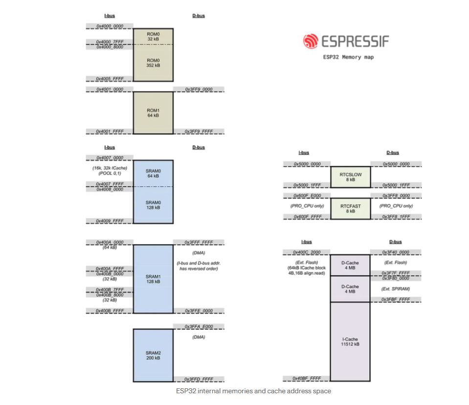
ESP32 Memory Architecture Overview
| Memory Type | Description |
|---|---|
| ROM | ~448 KB (contains bootloader, core libraries) |
| SRAM | ~520 KB (Internal) |
| RTC SRAM | 8 KB (for deep sleep state retention) |
| Flash | External (usually 4MB or more via SPI) |
| PSRAM (opt) | Up to 8 MB (optional external via SPI/QSPI) |
ESP32 Internal Memory Breakdown:
| Region | Size | Function |
|---|---|---|
| IRAM (Instruction RAM) | 128 KB | Stores executable code |
| DRAM (Data RAM) | 328 KB | Heap, global/static variables |
| RTC Fast/Slow RAM | 8 KB | Low-power memory for deep sleep |
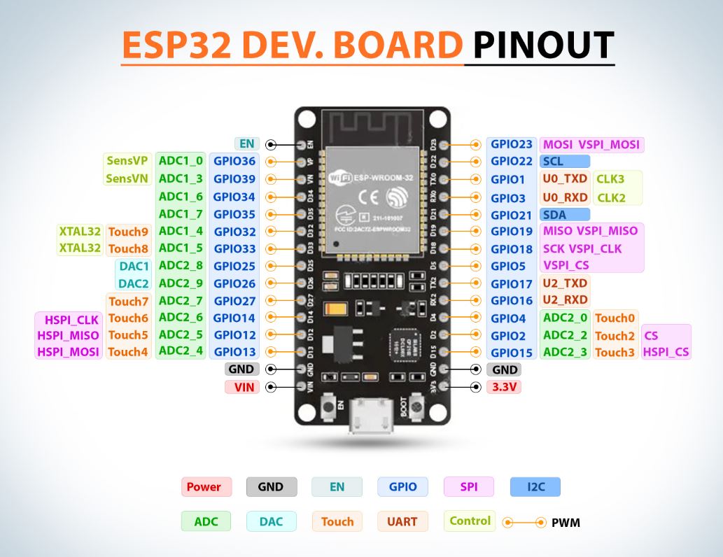
ESP32 SPI Flash Default Pin Mapping:
| Signal | GPIO |
|---|---|
| CS (Chip Select) | GPIO15 |
| CLK | GPIO6 |
| MISO (Q) | GPIO7 |
| MOSI (D) | GPIO8 |
| WP (Write Protect) | GPIO10 |
| HOLD (HD) | GPIO9 |
ESP32 PSRAM Default Pin Mapping:
| Signal | GPIO |
|---|---|
| CS | GPIO17 |
| CLK | GPIO16 |
| D/Q0 | GPIO8 |
| D/Q1 | GPIO9 |
| D/Q2 | GPIO10 |
| D/Q3 | GPIO11 |
Note: PSRAM and Flash can share the SPI bus in QSPI mode.
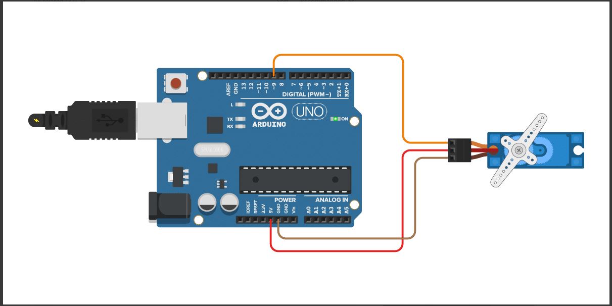
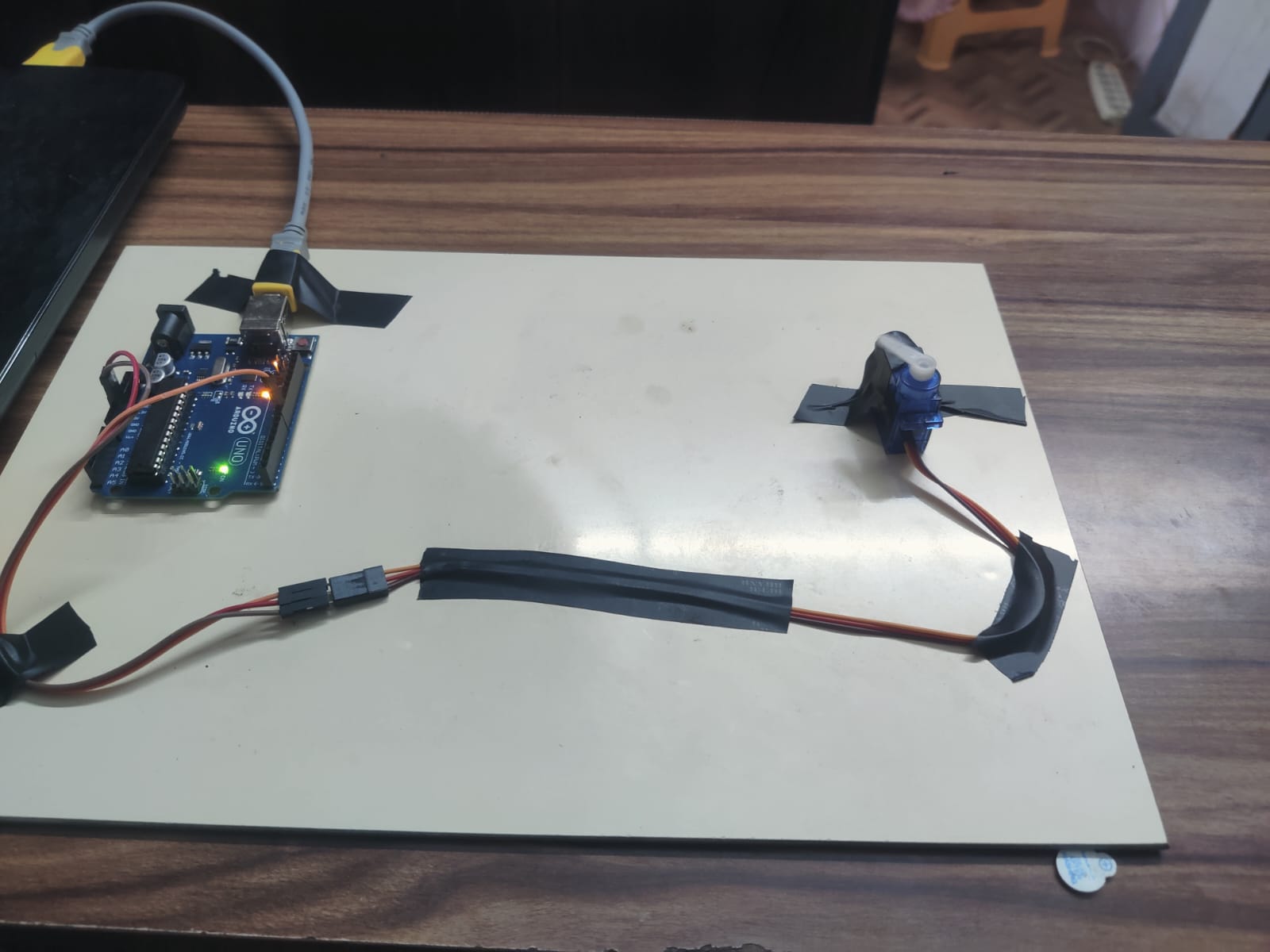
Connect the servo motor to the Arduino: Connect the signal wire of the servo to a digital pin on the Arduino (e.g., pin 9), and connect the power and ground wires of the servo to a power supply (e.g., the 5V and GND pins on the Arduino).
      Include the Servo library: At the beginning of your Arduino sketch, include the Servo library
      by adding the following line of code:
      #include
        Create a Servo object: In the setup() function of your sketch, create a Servo object by declaring
          a variable of type Servo. For example:
        Servo myServo;
        Attach the servo: In the setup() function, use the attach() method of the Servo object to attach
          the servo to the digital pin you connected it to. For example:
          myServo.attach(9);
        Set the servo position: In the loop() function, use the write() method of the Servo object to
          set the position of the servo. The write() method takes a valuebetween 0 and 180, where 0 is the
          minimum position and 180 is the maximum position. For example:

        myServo.write(90); // sets the servo to the middle position
        Delay and repeat: After setting the servo position, use the delay() function to wait for a short
        period of time before setting the position again. This will cause the servo to move to the new
        position gradually. Repeat this process in a loop to continuously control the servo position.
        Here's an example code snippet that sets the servo to the middle position, waits for 2 seconds,
        then sets the servo to the maximum position and waits for
        another 2 seconds before repeating the cycle:


             #include
            Servo myServo;
            void setup() {
            myServo.attach(9);
            }
            void loop() {
            myServo.write(90); // sets the servo to the middle position
            delay(2000);
            myServo.write(180); // sets the servo to the maximum position
            delay(2000);
            }
            Note that you may need to adjust the delay time and servo position values to suit your specific
              requirements.