Group Assignment Summary – Computer-Controlled Cutting
As part of the group assignment, we conducted safety training and characterized the laser cutter by analyzing important parameters such as focus, power, speed, kerf, and joint clearance. Various test patterns were cut to determine the optimal machine settings for accurate and clean cutting results. We measured the kerf value and evaluated different slot dimensions to identify the best press-fit tolerance for assembly. These experiments helped us understand how machine settings and material properties affect cutting quality and dimensional accuracy. The knowledge gained from this characterization process was essential for designing precise laser-cut parts and successful press-fit constructions in the individual assignment.
Hero Shot
Parametric Construction Kit
My plan is to design the Parametric Construction Kit by Solidworks and make the kit by 3mm cardboard sheet . Here is my Step by step process:Click Here www.solidworks.com
Solidworks Parametric 2D Modelling Workflow Begin by defining the part's purpose and fabrication method (e.g., laser cutting, CNC, 3D printing). Open a new part in SolidWorks and select an appropriate sketch plane. Set document units and create global parameters using equations or a design table to drive dimensions. Sketch from the origin for consistency, using geometric relations and smart dimensions to ensure parametric control. Use centerlines for symmetry and constrain all geometry to avoid under- or over-defined sketches.
Assign variable names to key features like length, width, and slot size for easy adjustments. Mirror entities and use patterns where needed. Always fully define sketches before proceeding. Use equations to link dimensions for parametric flexibility, avoiding hardcoded values. Export clean 1:1 DXF files for laser/CNC, ensuring no extra points or open contours exist.
Label key dimensions, add notes for material and thickness, and document version info. Use fabrication-friendly tolerances (e.g., slot fit clearance, laser kerf). Save templates for reuse and archive designs with notes and fabrication feedback. Maintain a sketch library for FabLab users. Encourage documentation, modularity, and standard practices for repeatable results. This structured workflow ensures precise, editable, and fabrication-ready 2D sketches. Preparation
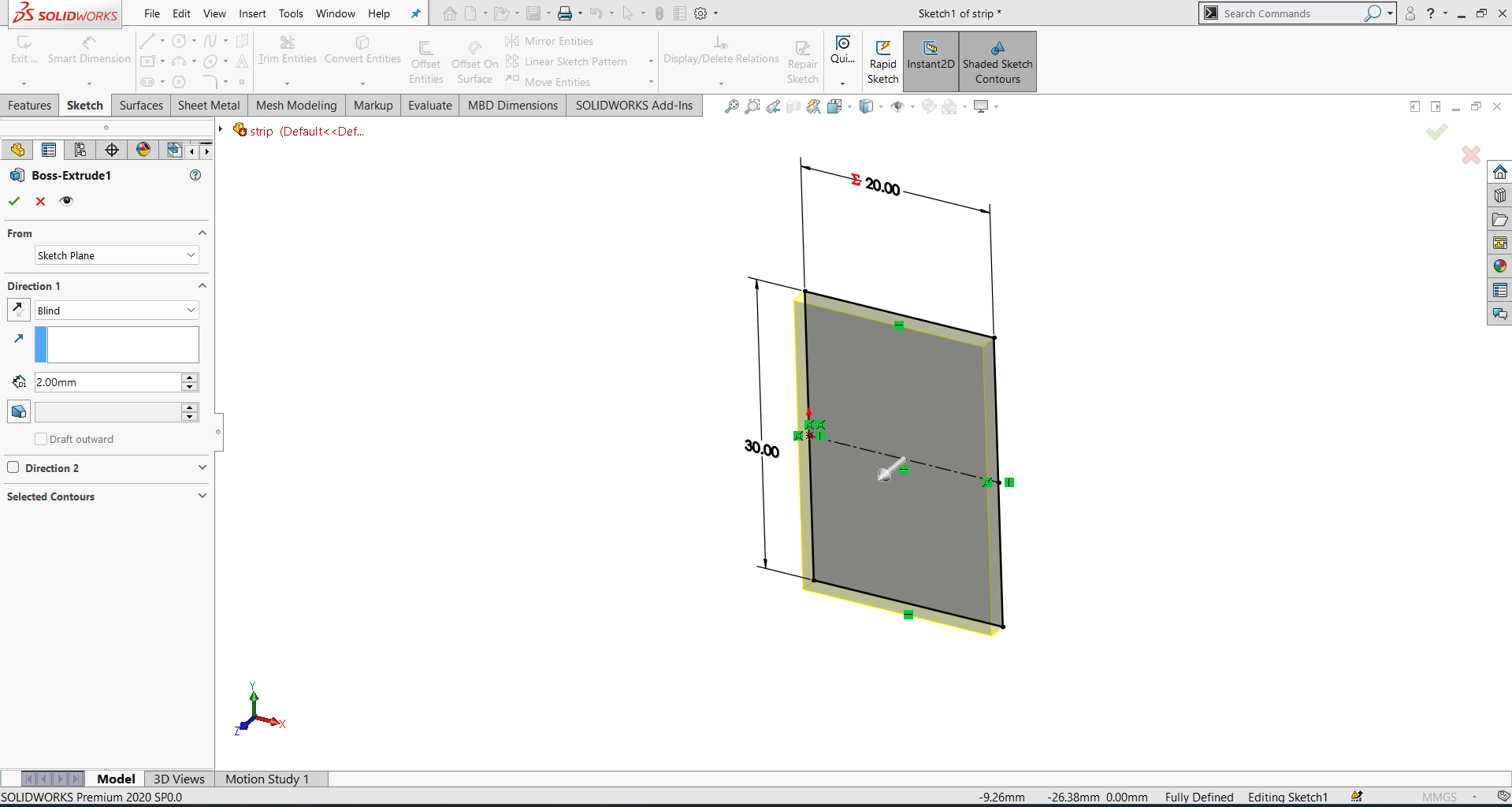
launched SolidWorks and navigated to the Part Design workbench. After opening the application, I selected “New” and chose “Part” to begin creating a new component. This automatically opened the Part Design environment, where I could start sketching and modeling 3D parts using features like extrude, revolve, and cut. The interface was ready for designing individual components.
I clicked Create Body to define a solid body for modeling, then selected Create Sketch to begin a 2D sketch. A prompt appeared to choose a plane—Top, Front, or Right. I picked the Top Plane, and the sketching environment opened, allowing me to draw shapes for 3D operations.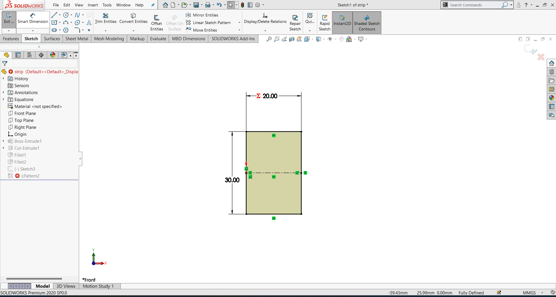 > > |
 > > |
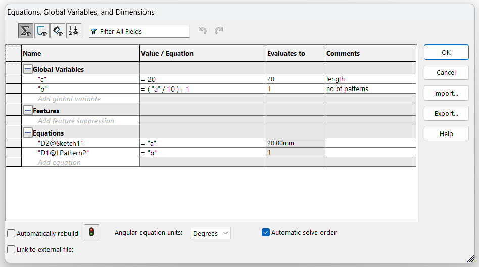
In SolidWorks, i can define global variables and equations like this:
Go to Tools → Equations.
In the Global Variables section, add:
a = 20
b = "a / 10 - 1"In SolidWorks, you can define global variables and equations like this:
Go to Tools → Equations.
In the Global Variables section, add:
a = 20
b = "a / 10 - 1"
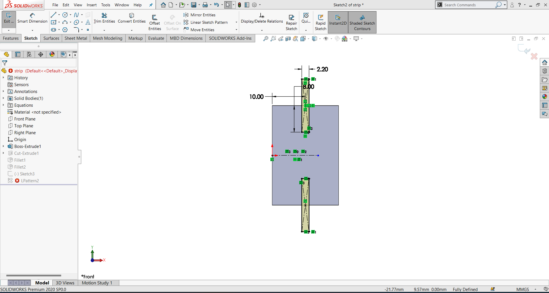
To link dimensions to global variables in SolidWorks, first create a sketch or feature and add dimensions as needed. Click on the dimension you want to control, and in the Modify dialog box that appears, delete the current value. Replace it with the global variable name, enclosed in double quotes and preceded by an equal sign—for example, ="a". Press Enter or click the green checkmark to confirm. The dimension is now driven by the value of the global variable. When you update the variable in Tools → Equations, all linked dimensions automatically adjust, enabling easy parametric design changes and updates.
 > > |
 > > |
To add equations and create relationships between global variables in SolidWorks, go to Tools → Equations. In the Equations section, click to add a new row. Type the name of the new variable (e.g., "Height") and in the equation field, enter the expression using an existing variable (e.g., "Length / 2"). It should look like:
Copy
Edit
"Height" = "Length" / 2
Press Enter to confirm. SolidWorks will evaluate the relationship and assign the correct value. These equations maintain parametric control, so when you change Length, Height
will automatically update according to the defined formula.Rebuild Model → Press Ctrl + B to update sketch based on equations.
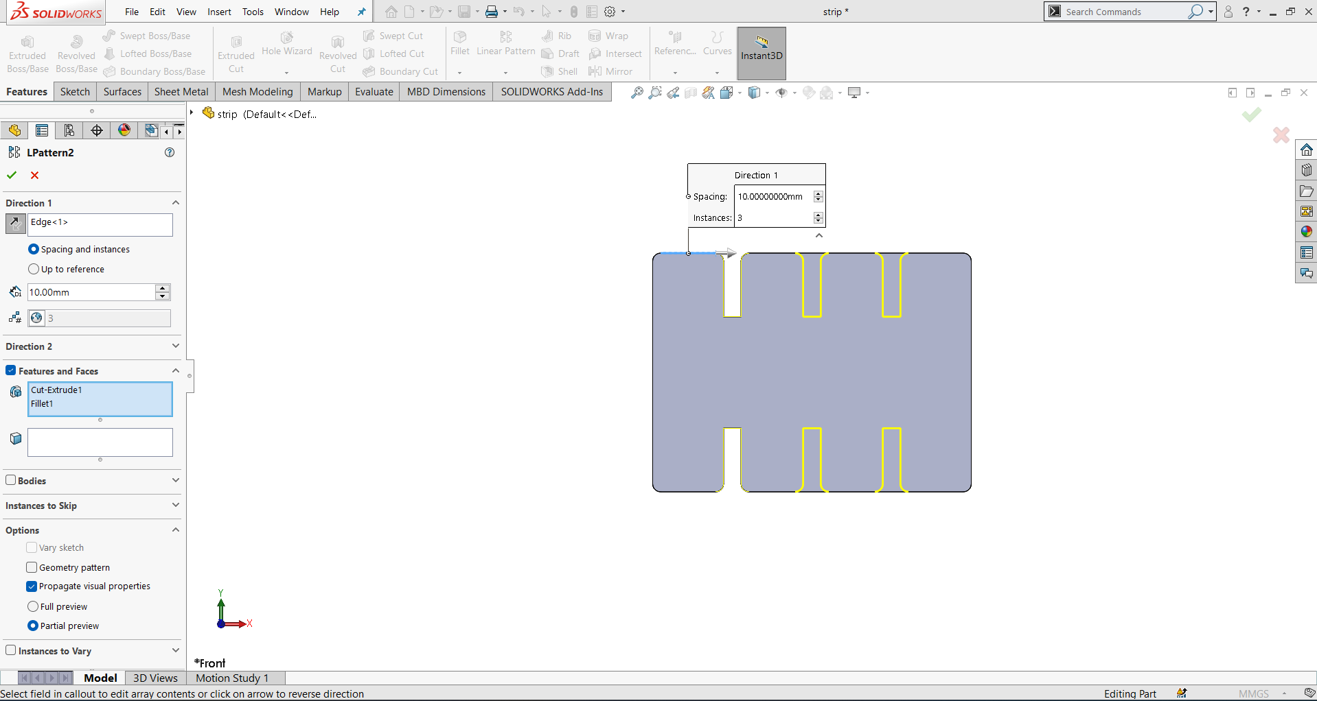
Parametric control in SolidWorks allows you to drive your model using global variables and equations. To achieve this, define variables in Tools → Equations, such as "Length" = 100 or "Width" = 50. Link these variables to sketch dimensions by replacing dimension values with expressions like ="Length". When you change a variable’s value in the Equations manager, all linked dimensions and features update automatically. This ensures your design remains consistent and easy to modify. Parametric control is especially useful for design iterations, enabling quick updates without manually adjusting each dimension or feature throughout the model.
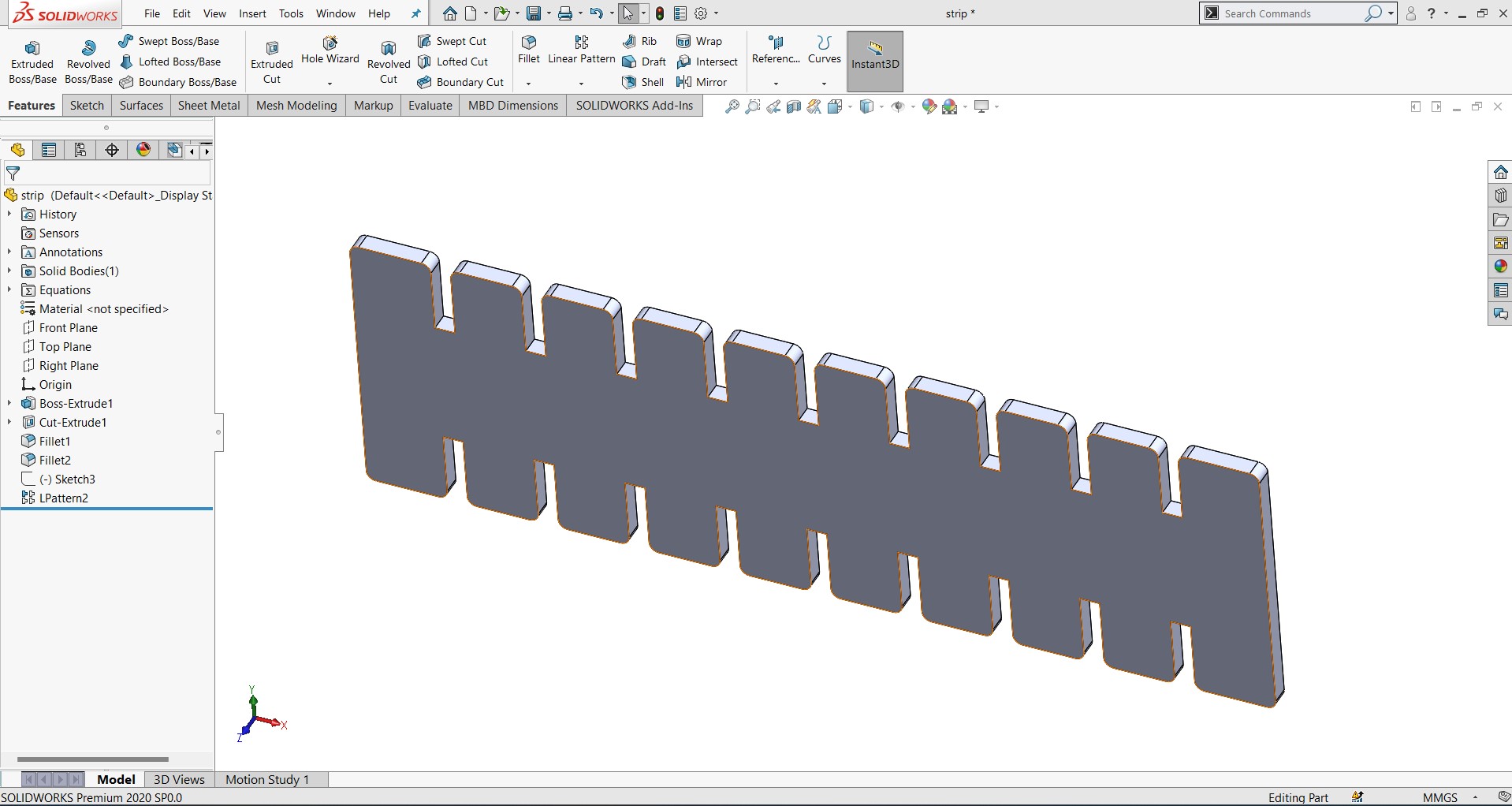
Result
I now created a parametric 2D design in Solidworks This allows easy updates to the design then and there i want to change .
Laser cutting
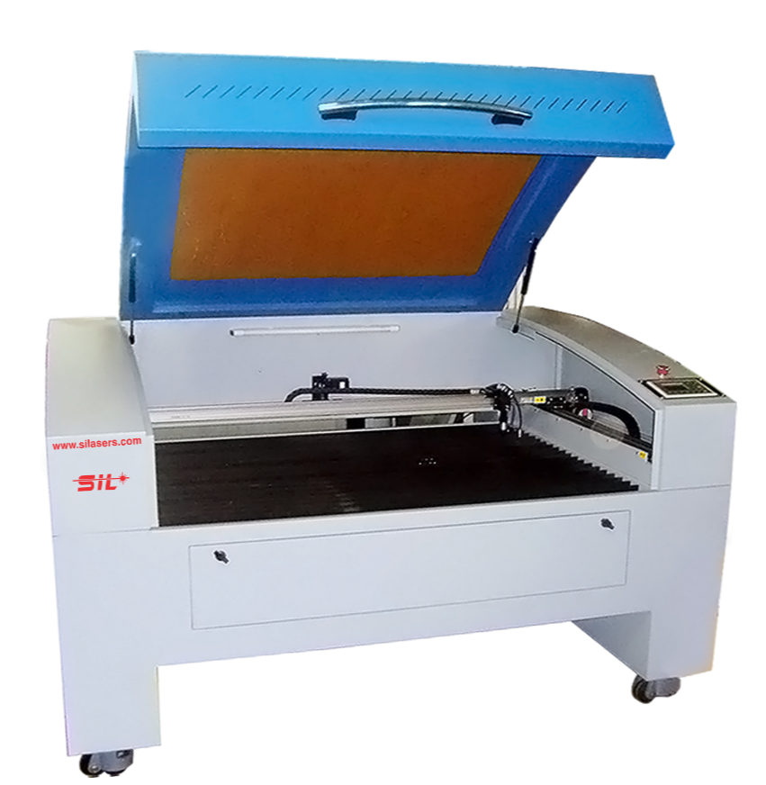
Laser Engraving and Cutting Machine - Accucut
Click Here For SILASERS Laser Engraving & Cutting Machines
A CO2 laser engraving and cutting machine is a versatile tool used for engraving and cutting various materials using a high-powered laser beam. The “CO2” in the name refers to the type of laser it uses, which generates the laser beam by exciting carbon dioxide gas.
SIL laser engraving machine is versatile & finds application in signage, indoor & outdoor advertisement, art & craft, gift, shoes, toys, garments, model cutting, papers & packaging, wood & MDF cutting industry, interior, decorators and many more. SIL built laser engraver which is engineered & manufactured in India.
Engraving: CO2 laser machines can etch intricate designs, text, logos, and graphics onto various materials such as wood, acrylic, glass, leather, paper, fabric, and more. They offer high precision and can create detailed and permanent engravings.
Cutting: These machines can also cut through different materials with precision. They are commonly used for cutting thin materials like paper, cardboard, fabric, thin wood, and acrylic sheets. The laser beam is focused on the material, generating intense heat that vaporizes or burns through it, resulting in precise cuts. Material versatility: CO2 laser machines can work with a wide range of materials, including non-metallic materials like wood, acrylic, leather, fabric, rubber, glass, plastic, and more. They are not suitable for cutting or engraving metals, as CO2 lasers are not typically powerful enough to handle metals effectively. Power and speed: CO2 laser machines come in various power levels, typically ranging from 30 to 150 watts. Higher power allows for faster cutting and engraving speeds and enables the machine to handle thicker materials. The power and speed settings can be adjusted based on the material and desired outcome.
Software and control: CO2 laser machines are typically controlled through dedicated software that allows you to import designs, create custom artwork, adjust settings, and control the machine’s movements. Popular software options include CorelDRAW, Adobe Illustrator, AutoCAD, and dedicated software provided by the machine manufacturer.
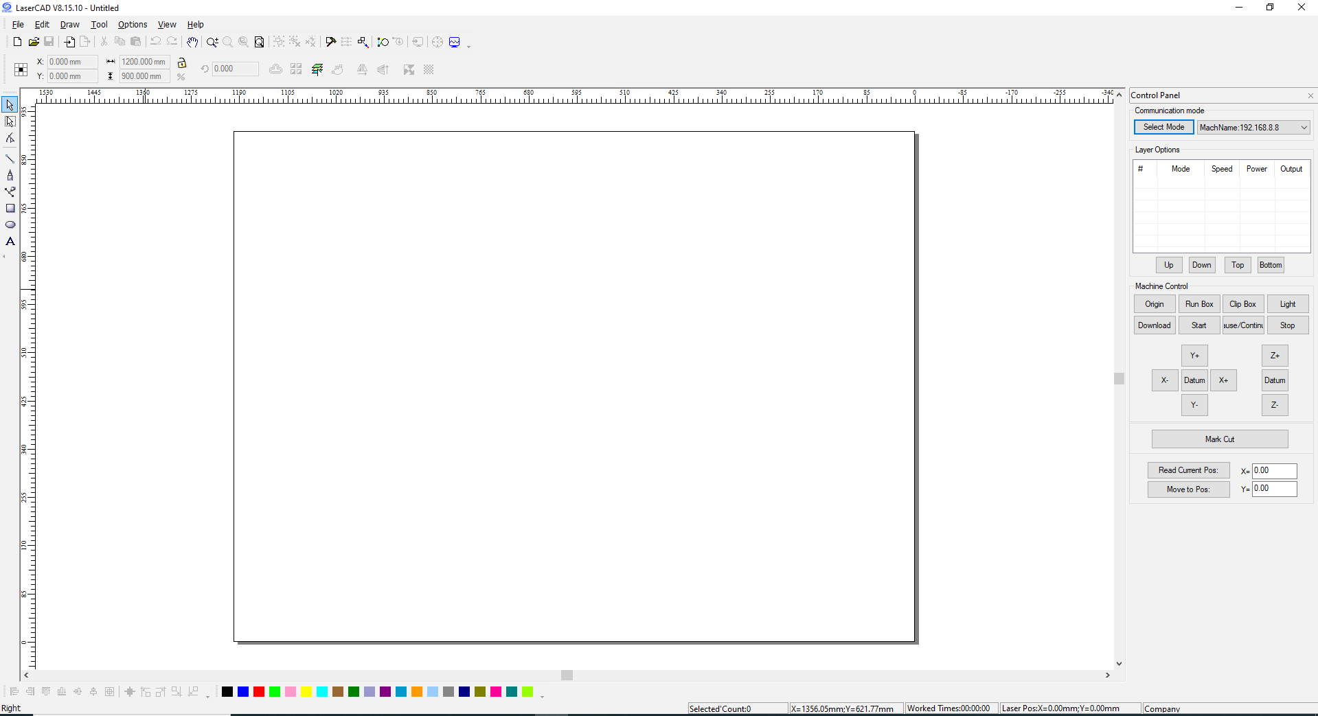
I opened the SIL laser engraving machine’s control software, LaserCAD v8.15.10, to begin preparing a new
engraving
Click Here LaserCAD Software v8.15.10
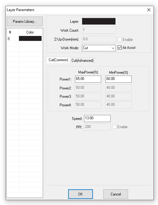
job. After launching the software, the interface loaded with the default workspace and machine configuration. I verified the machine was properly connected via USB and that the correct COM port was active. In the LaserCAD interface, I selected the appropriate working area that matches the machine’s bed size. The software provided tools for importing vector files, setting layer parameters, and adjusting laser power and speed. With LaserCAD v8.15.10, I could efficiently prepare designs for engraving or cutting with precise control.
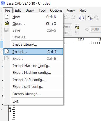
imported the dxf_path.cdr file into LaserCAD by clicking File → Import, then selecting the CorelDRAW file. LaserCAD automatically converted the design into editable vector paths. The imported design appeared on the workspace, ready for setting layer parameters, laser speed, and power before sending it to the engraving machine.
 >
>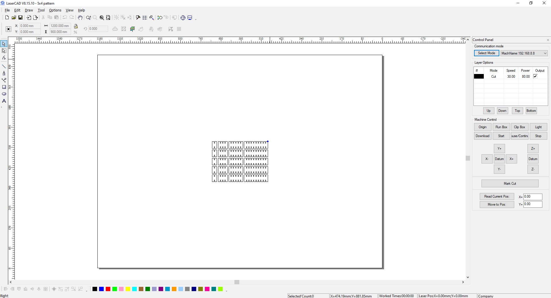
Each layer from the original design was preserved, allowing me to assign different laser settings such as power, speed, and frequency for cutting or engraving. The software showed a preview of the job layout, matching the machine’s working area. I could now easily adjust parameters and prepare the design for precise laser processing. The file was ready for further editing or immediate job execution.
 >
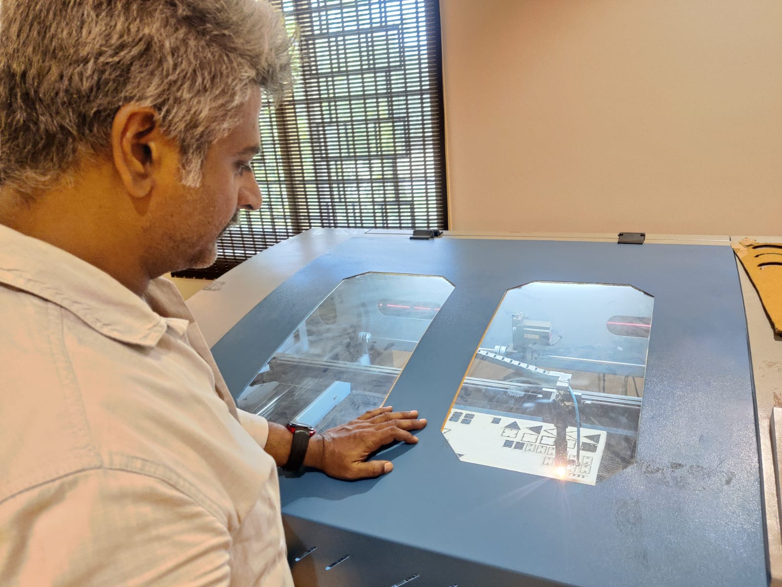
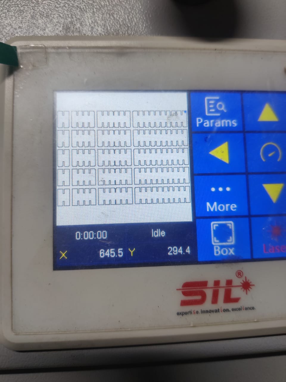
>I approached the SIL laser engraving machine and saw the imported design clearly displayed on the machine’s screen, confirming the file loaded correctly. The interface on the screen showed the design’s layout, positioning, and basic settings, matching what I had prepared in LaserCAD. Everything looked ready for the job to start.
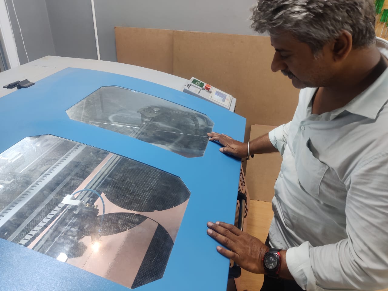
The next step was to place the cardboard material inside the machine’s working area. I carefully positioned the cardboard sheet flat and secure, making sure it was aligned properly to avoid any movement during engraving. Once the material was in place, I fixed the origin point on the machine. This involved moving the laser head to the starting position, usually the lower-left corner of the material or wherever the design origin was set, and then setting this position as the home or origin on the machine’s control panel. This ensures the laser follows the exact coordinates of the design file.
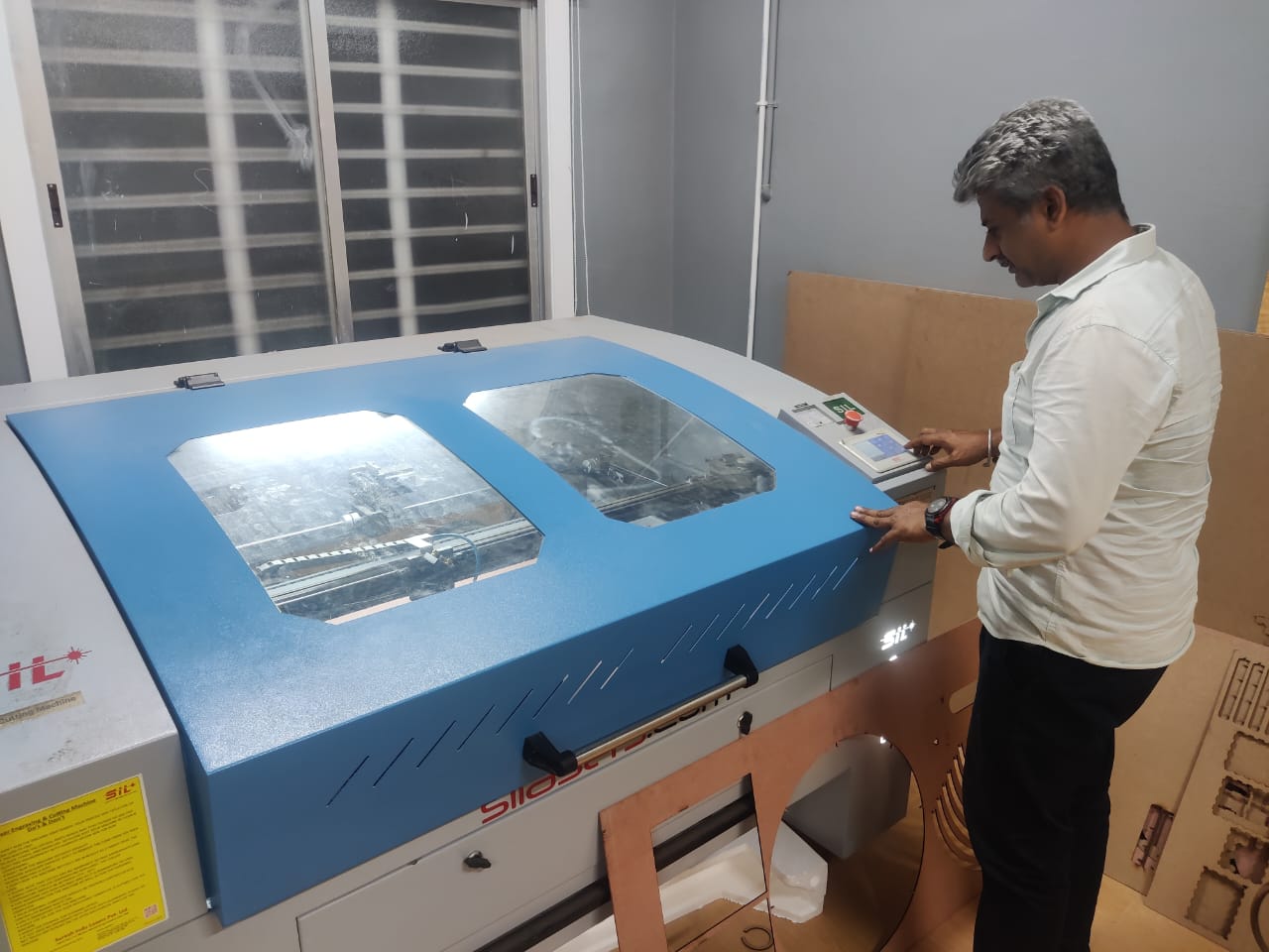
With the origin fixed and the material ready, I double-checked all safety precautions and the laser parameters on the screen. After confirming everything, I started the machine. The laser began its precise movements, cutting and engraving the cardboard according to the design. I monitored the process closely to ensure accuracy and safety throughout the job
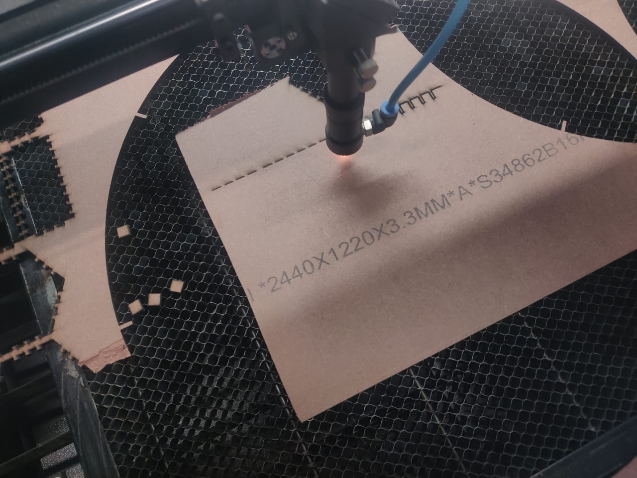
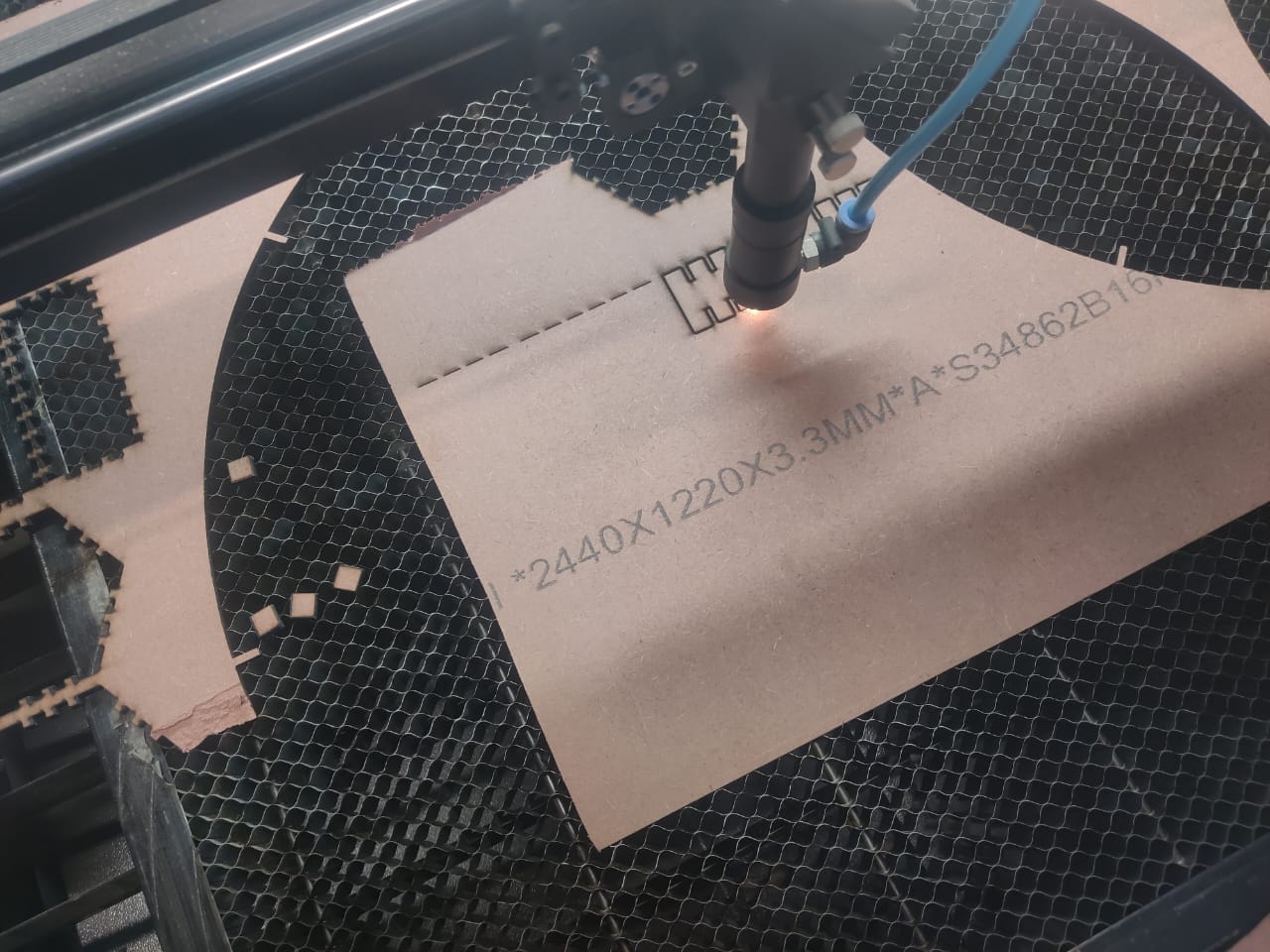
My SIL laser engraving machine started cutting as the CO2 laser fired up, producing a bright, focused beam. I could see the laser’s flame-like glow precisely moving along the design path, gradually cutting through the cardboard with smooth, controlled motions, creating clean, accurate cuts exactly as planned.
My first pass is going smoothly without any issues. The laser moves steadily along the design paths, cutting cleanly through the material. The edges look sharp and precise, and the machine is operating quietly. Everything is progressing exactly as expected for a successful.
After my second pass, the pieces are cut completely and cleanly. The edges are smooth, and the design looks sharp and attractive. The precise cuts enhance the overall appearance, making the final result visually appealing and professional. The laser settings worked perfectly for this material and design
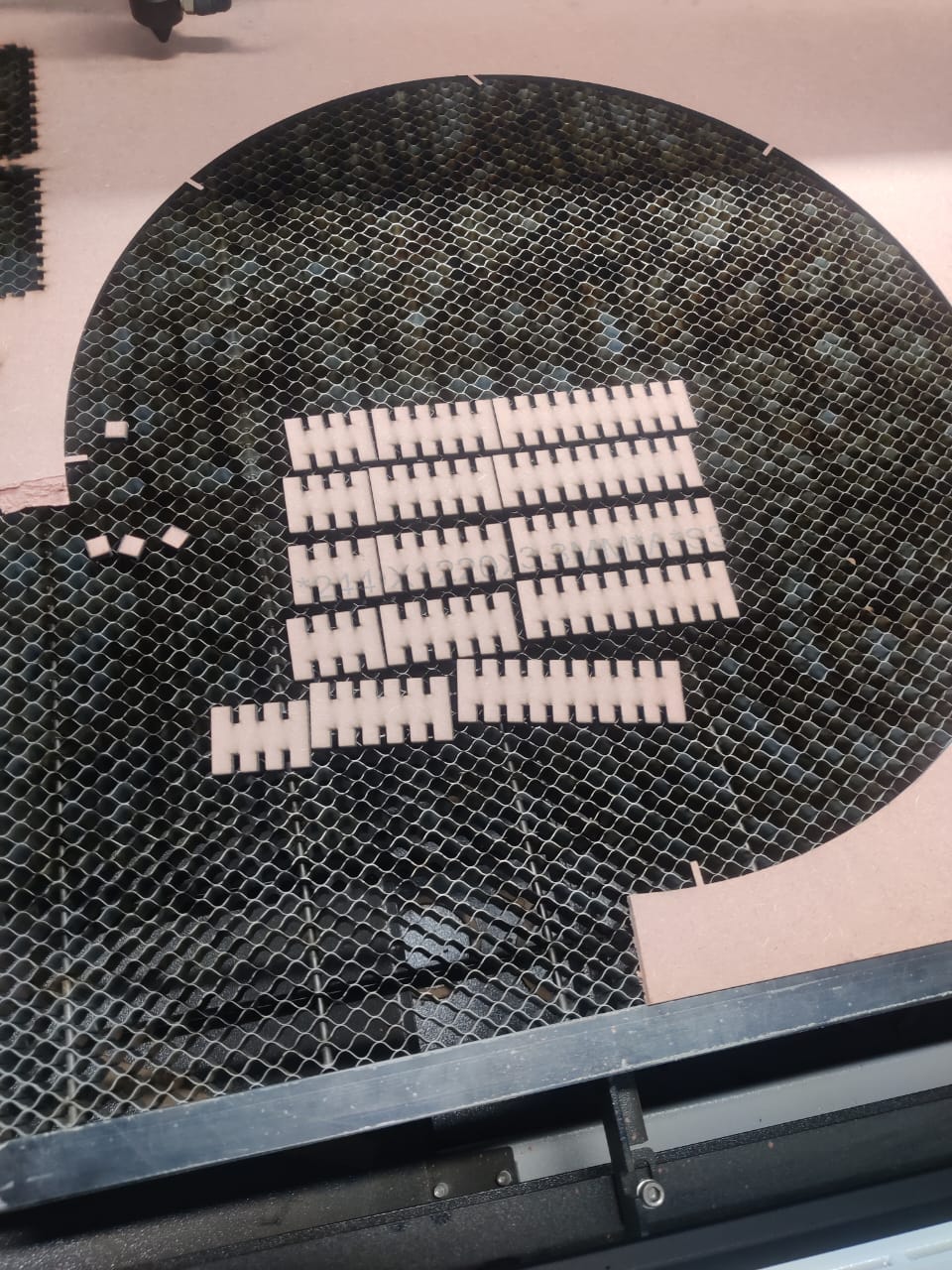
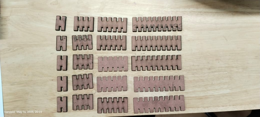
The pieces came out smoothly with excellent dimensional stability. Each cut is precise, matching the design dimensions accurately. The material shows no signs of warping or distortion, confirming the laser’s consistent performance. Overall, the quality of the cut pieces meets the expected standards perfectly.
 > > |
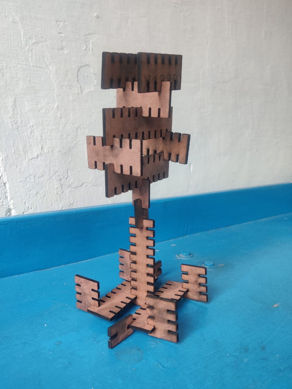 > > |
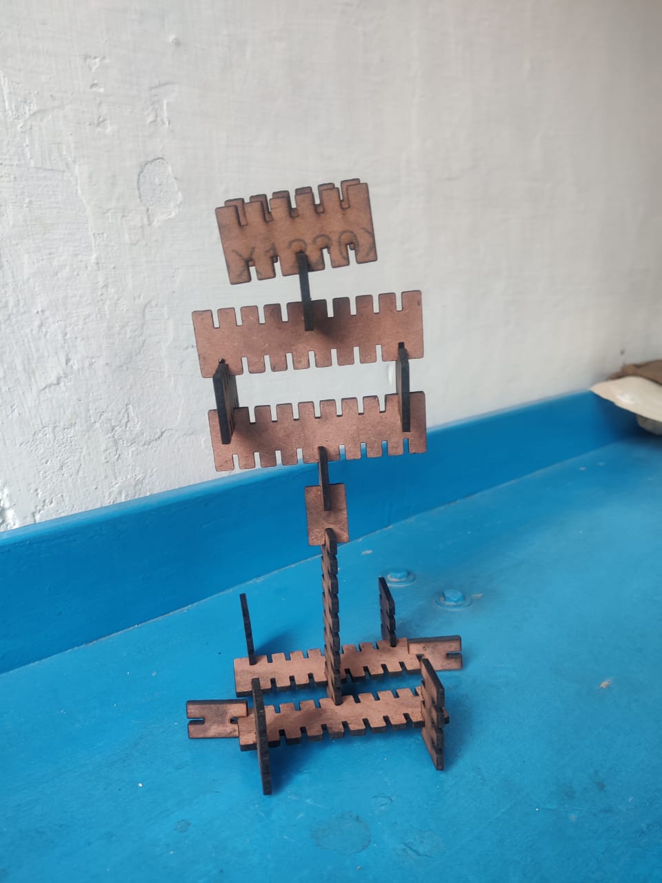
I finally assembled my interlocking parametric design, and all the parts fit together perfectly without force. The precise laser cuts ensured smooth joints and stable connections. The final structure is sturdy, well-aligned, and visually appealing, showcasing the effectiveness of parametric design and accurate fabrication using the SIL laser machine.
Vinyl Cutter
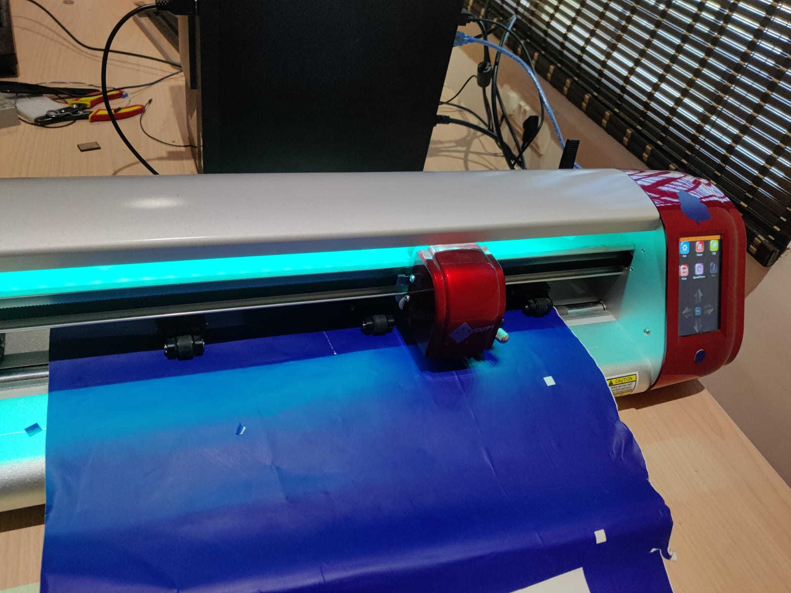
I used Skycut C24(720mm) vinyl Cutting plotter
Click Here for Skycut C24(720mm) vinyl Cutting plotter
1. 800G material cutting force which helps to cut materials like cardstock, fabric etc.
2. Supports multi-languages that cover almost all languages.
3. Less Space covering plotter.
4. Multi-interface which support USB, hard drive and WIFI etc.
5. Large screen for easy handling and avoid troubles.
6. Nice colour finishing which makes it provides shining in the light.
Cutting Blades
It provide various angle of blades based on various type of cutter from small to large, basically we provide the blades range in 30° , 45° , 60°.
Cutting tools
All products comes with capsules type cutting tubes which provides you various function like stability, accuracy and speed for smooth lining up and cutting.
Drawing pen kit with Mat
Skycut provides drawing pen kit and cutting mat for better gripping and cutting purpose, D series comes with 2 drawing pen and cutting mate.
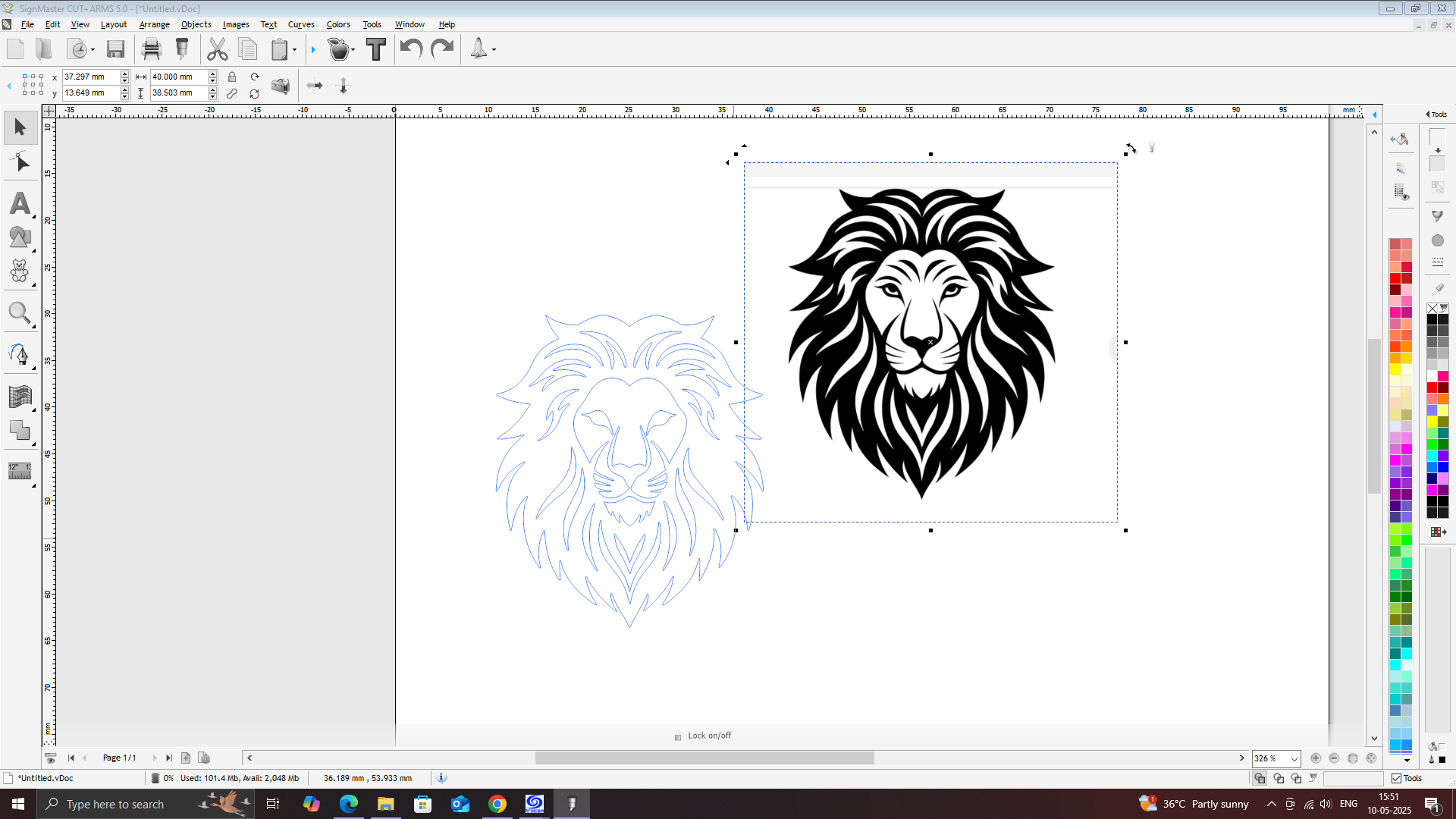
here is a Step-by-Step Procedure to Cut a Sticker Using SignMaster
Click Here For SignMaster Software
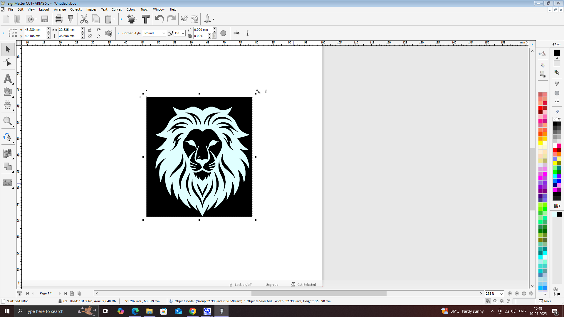
Open SignMaster Software
Launch SignMaster on the computer connected to the vinyl cutter.
Create or Import Design
You can draw directly using SignMaster’s tools (text, shapes, etc.)
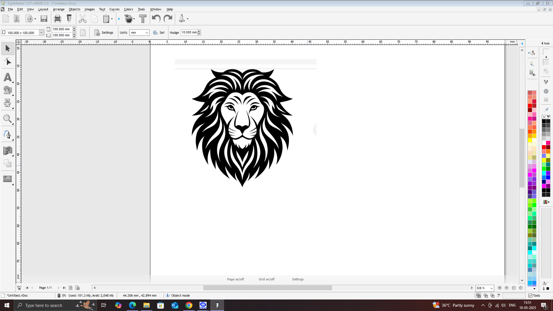
Or import a design (preferably in SVG, DXF, or PNG format).
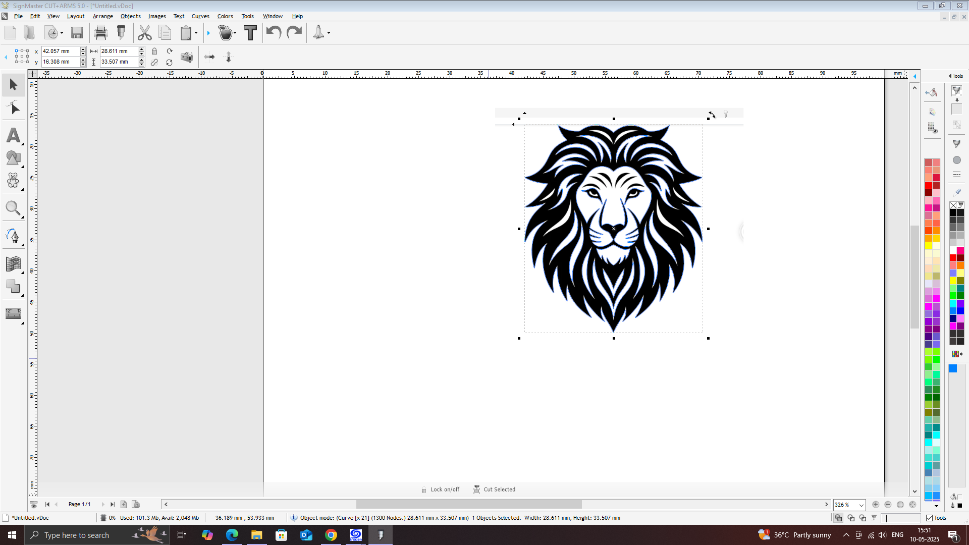
Convert to Vector (if needed)
If you imported an image, use the Trace tool to convert it to a vector path suitable for cutting.
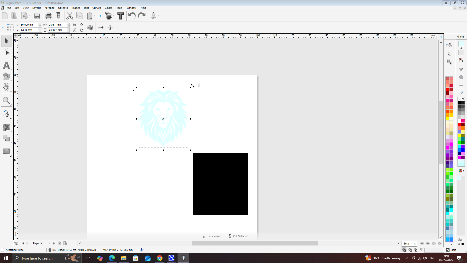
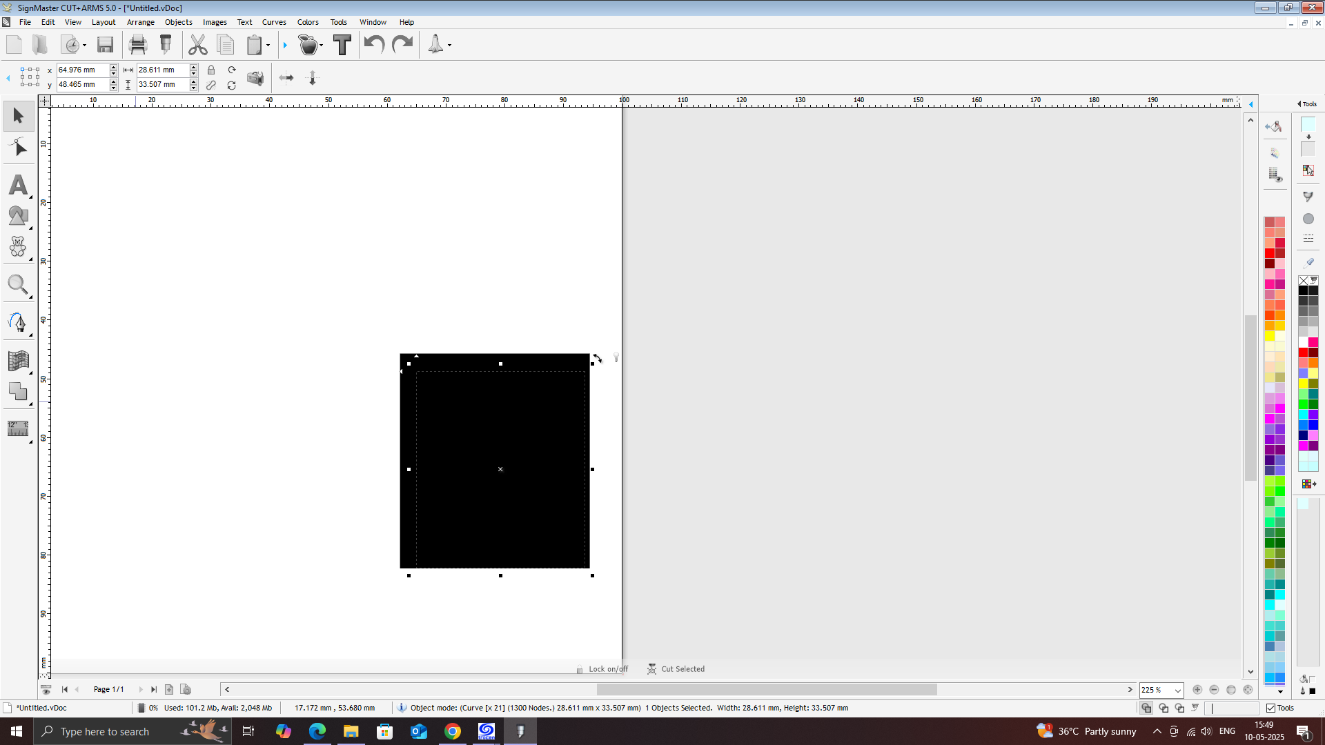
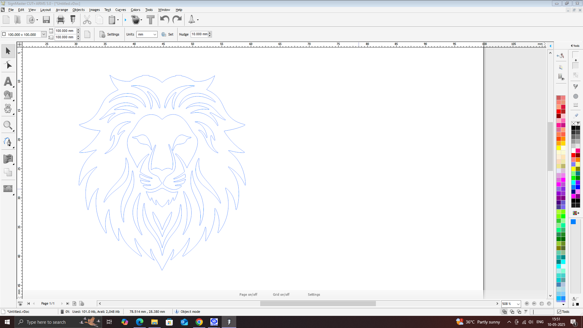
Resize and Position
Adjust the size of your design to fit the sticker sheet.
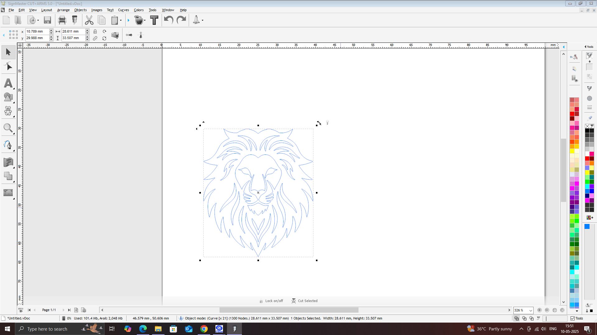
Place the design within the cutting area visible on the screen.
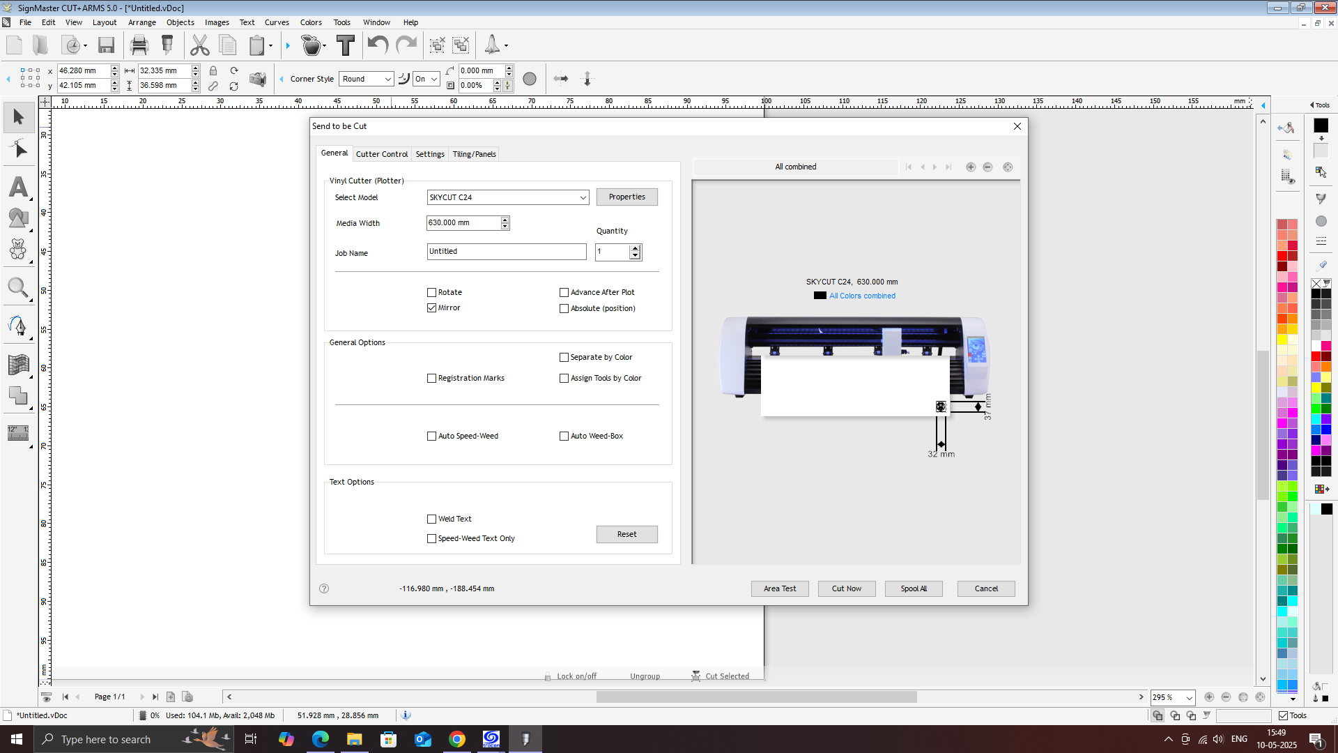
Go to Cutter Settings.
Number of Passes (usually 1)
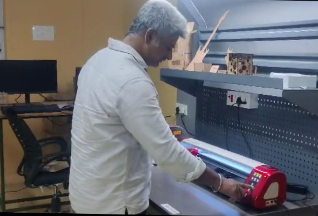
Load Vinyl Sheet into the Cutter
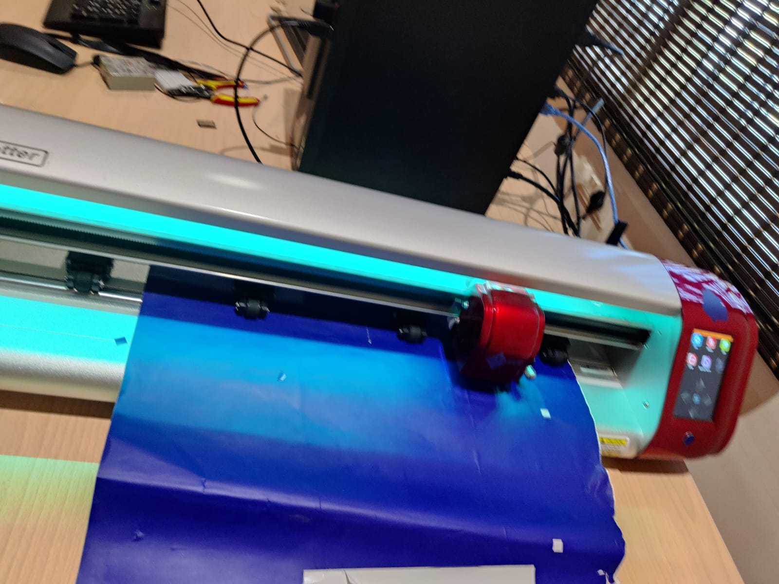
Align it properly and use the rollers to hold it in place.
Set the origin point (usually lower-left corner) using the cutter’s control panel.
In SignMaster, click "Cut Now" or "Send to Cutter".
Weed the Vinyl
After cutting is complete, remove the vinyl sheet.
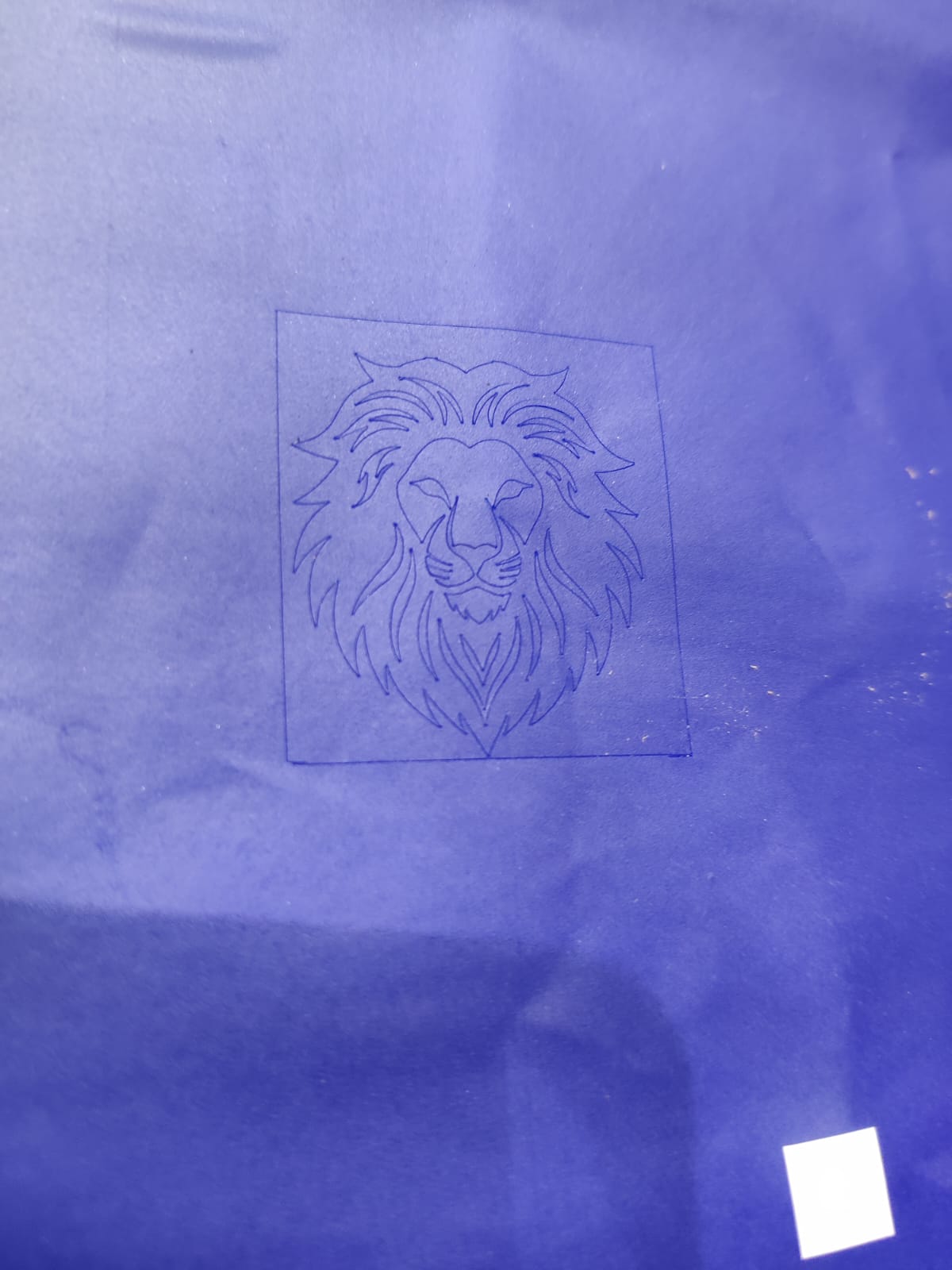
Use a weeding tool to carefully peel off the unwanted vinyl parts, leaving only the sticker design.
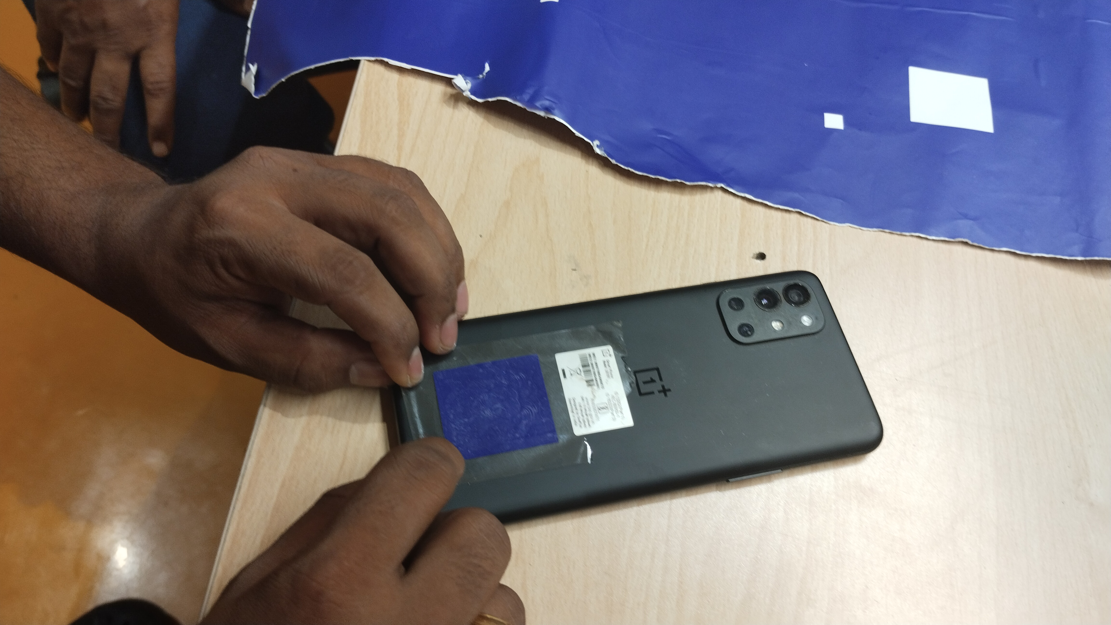
Apply Transfer Tape
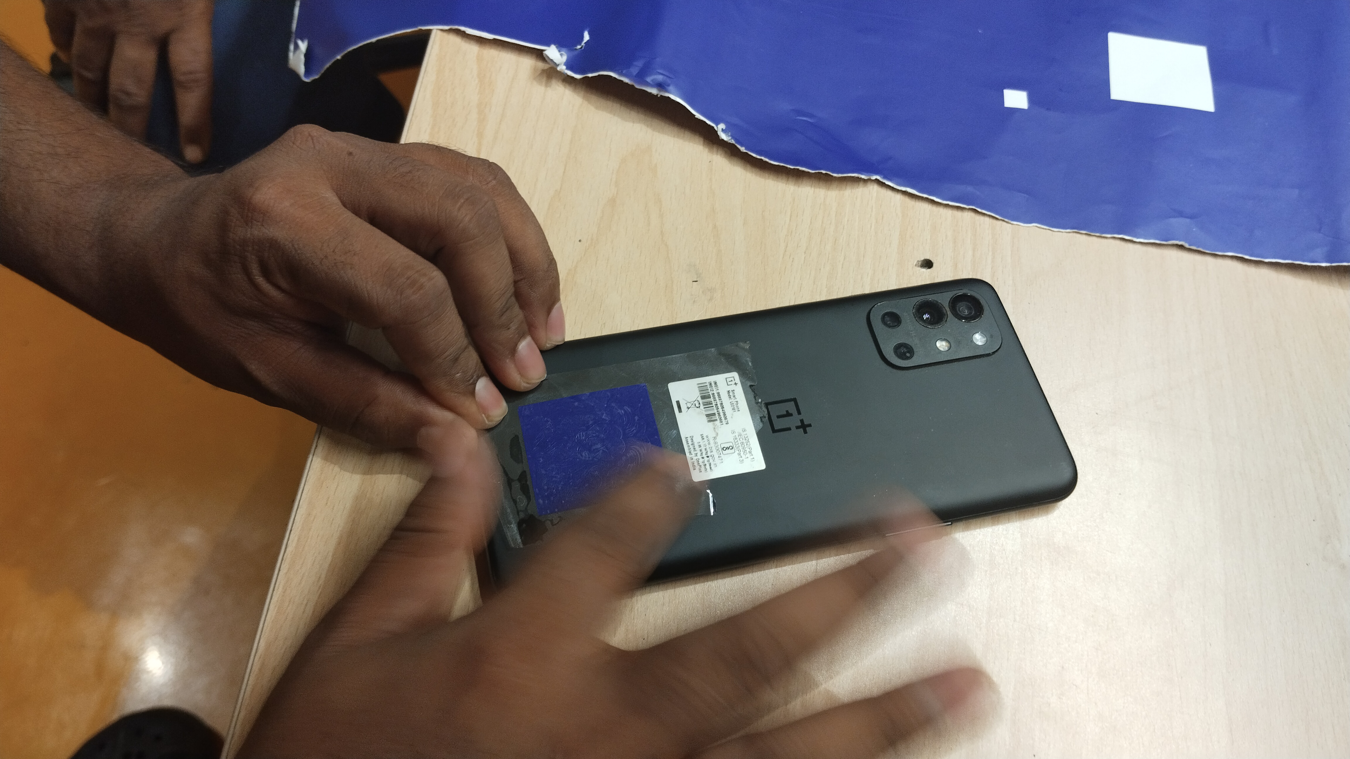
Place transfer tape over the weeded design to lift it from the backing.
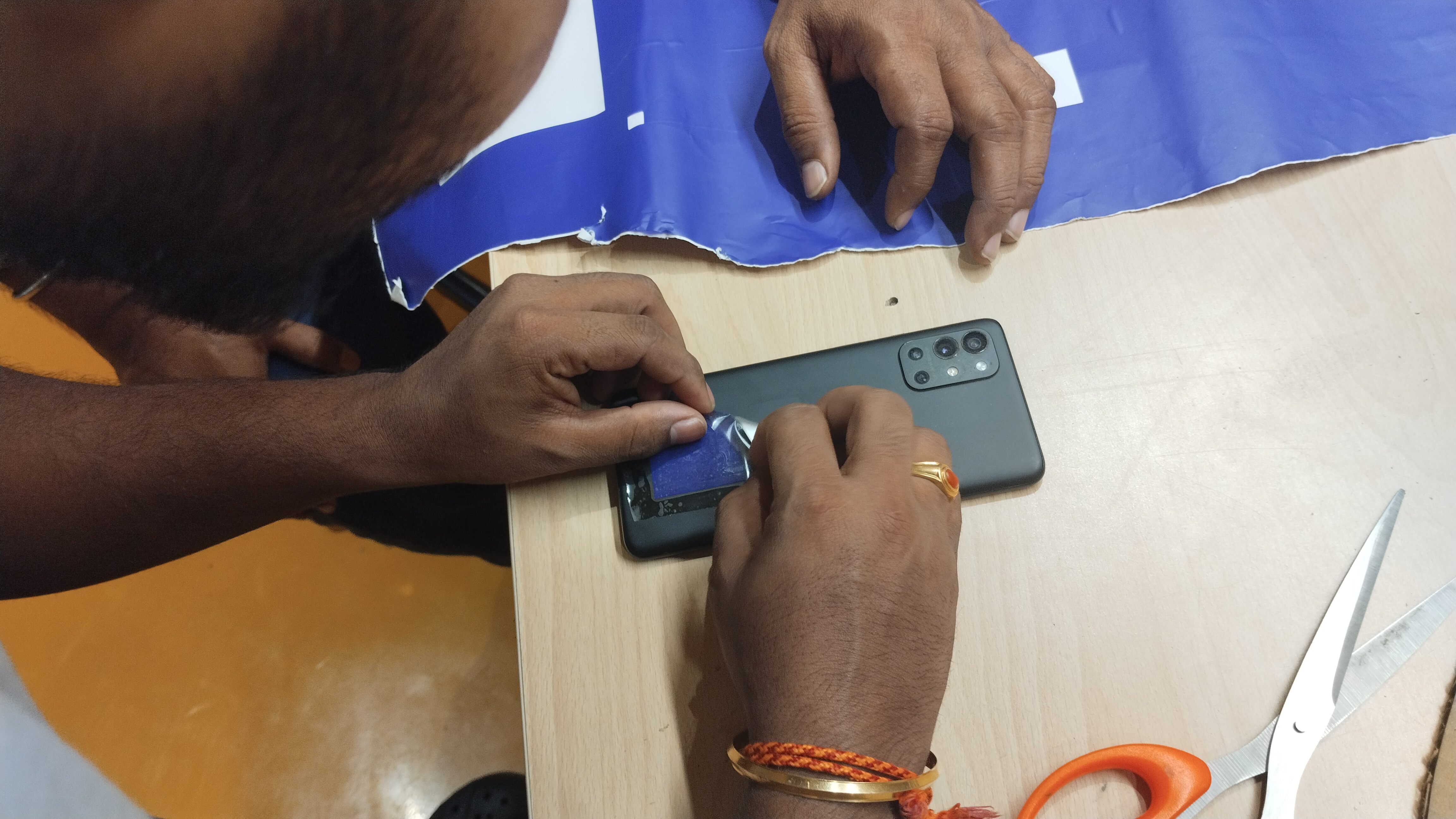
Apply the Sticker
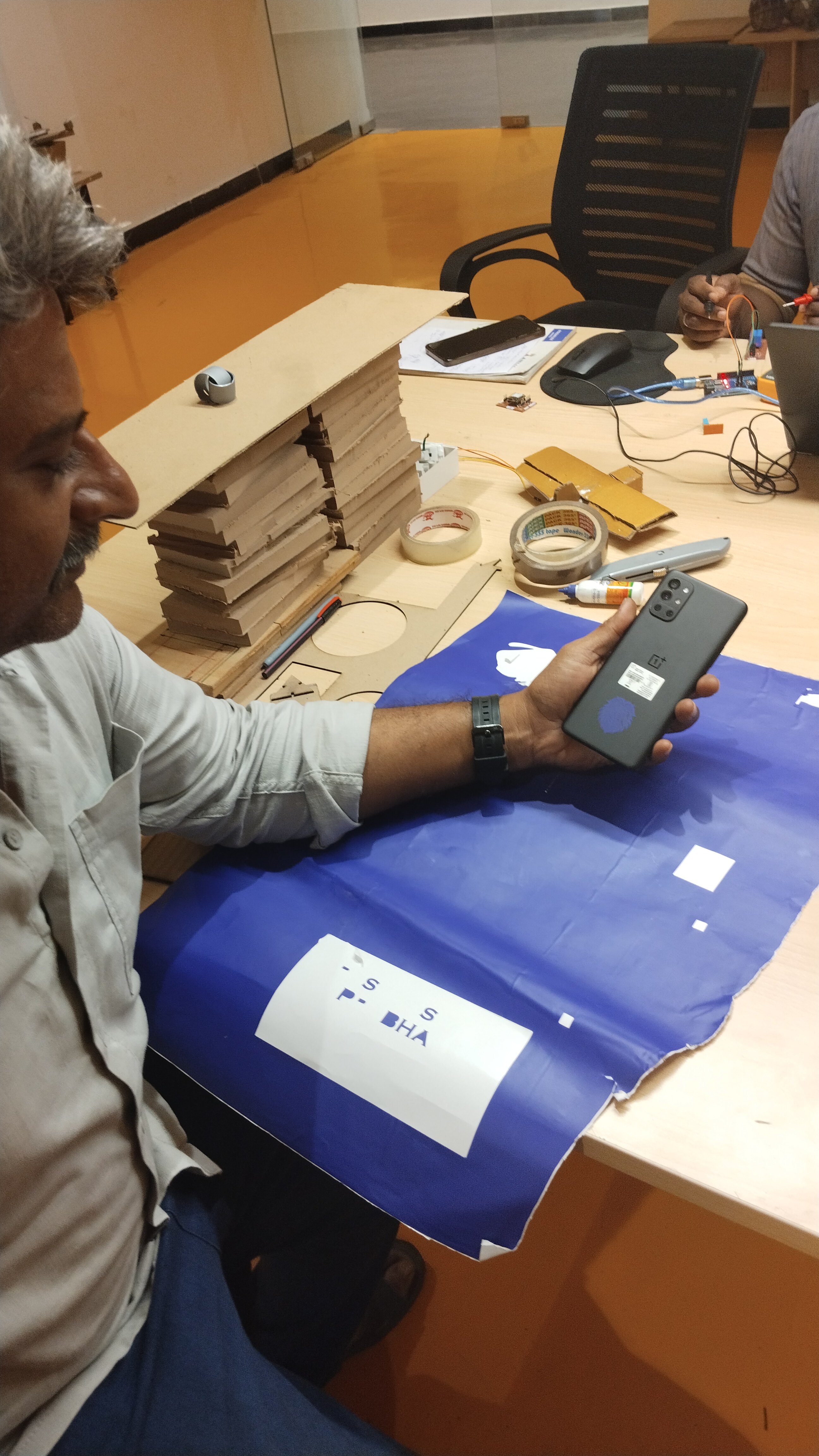
Peel the design using the tape and stick it to your desired surface.
Use a squeegee or card to press and remove bubbles.
Carefully remove the transfer tape, leaving the sticker in place.,