1.Model raster, vector
A raster is a digital representation of images formed by a rectangular grid of individual pixels or dots, where each pixel carries a specific color or intensity value. This structure allows for detailed image rendering by defining the color information at each point in the grid. Raster graphics are widely used in photography, digital art, printing, and screen displays because they can accurately capture complex color gradients and fine visual detail. However, since raster images are resolution-dependent, scaling them beyond their original size can result in pixelation or loss of quality, unlike vector graphics which remain crisp at any size.
I used GIMP (version 2.10.34) to create a 2D raster design for my assignment. First, I opened GIMP and created a new file by selecting the New Project option. I set the canvas size to 1920 × 1080 pixels to maintain Full HD resolution for better visual quality.
Raster Image

After entering the required dimensions, I confirmed the settings and created the file. The software then generated a blank canvas, which served as the main workspace for my design. This area is where all drawings, text, and images are placed and edited

his step helped me understand how to set up a proper workspace in GIMP before starting any design work. Choosing the correct canvas size is important because it determines the overall resolution and quality of the final image

Next, I selected the Text Tool and added the word “FabAcademy” on the canvas. I adjusted the font size and placement to make it clearly visible and balanced within the frame. This step helped me understand how to work with typography in raster graphics and how text can be modified using different font styles and alignment options.

After that, I imported a robot line image into the workspace using GIMP. The image appeared on the canvas as a separate layer, allowing me to edit it without affecting the background..

Then, I used the Bucket Fill Tool to add different colors inside the robot outline. By working carefully with layers and boundaries, I ensured the colors stayed within the drawing lines, which helped me understand basic coloring techniques and layer management in GIMP.

Finally, I used the Brush Tool to draw a simple boat scene. In the drawing, a man is standing in the boat and pushing a stick into the water to move it forward. This freehand illustration helped me practice digital sketching and painting. Through this assignment, I learned the basics of raster design, including text editing, image coloring, drawing, and layer handling.


vector
A vector is a mathematical quantity that possesses both magnitude (size) and direction, making it essential in accurately describing physical phenomena. In physics and engineering, vectors are widely used to represent quantities such as force, velocity, acceleration, and displacement, where the direction of the action is just as important as its strength. Vectors are typically represented graphically by arrows, where the length corresponds to magnitude and the arrowhead shows direction. Unlike scalar quantities, which have only magnitude, vectors provide a more complete description of motion and forces, making them fundamental tools in analyzing and solving real-world engineering and physics problems.
Vector Image
Vector Image
2. 2D
Key points about FreeCAD:<FreeCAD is an open-source 3D CAD modeler focused on parametric design. Parametric modeling allows you to easily modify designs by changing parameters like dimensions. You can build complex models using sketches, constraints, and features like pads, pockets, and patterns. FreeCAD supports scripting with Python, making automation and customization powerful and flexible.
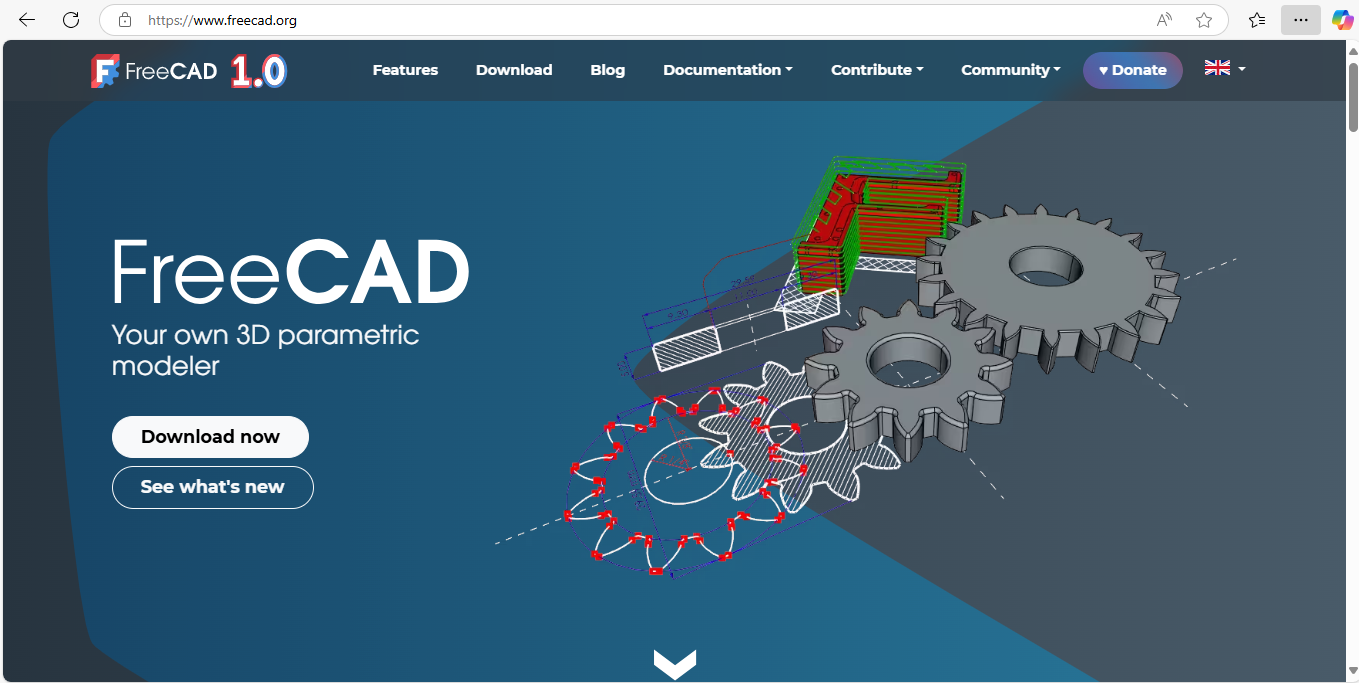
I downloaded FreeCAD 1.0 for my Windows PC as part of my Fab Academy journey to explore parametric 3D modeling. FreeCAD is an open-source, feature-rich CAD tool ideal for designing mechanical parts and assemblies. It supports sketch-based modeling, part design, and technical drawings, making it suitable for engineering applications. The installation was straightforward, and the interface is user-friendly with various workbenches for different tasks. I plan to use FreeCAD for designing components of my Fab Academy projects, including 3D printing, laser cutting, and CNC milling. Its parametric design capabilities help in easy modification and iteration of my designs.
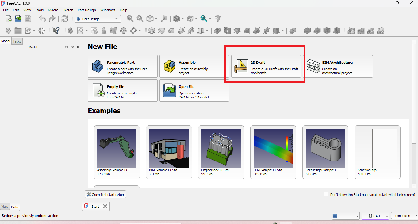
opened FreeCAD and selected "New File" to start a fresh project. From the workbench menu, I chose the "Draft" workbench to create 2D sketches. The Draft workbench is useful for basic 2D shapes like lines, rectangles, and circles, which are essential for initial design layouts. It provides simple tools to draw and modify geometry accurately. This step is the foundation for building more complex 3D models later in my Fab Academy projects.
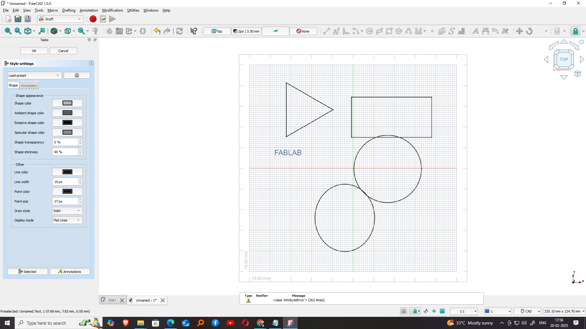
After entering the Draft workbench in FreeCAD, I selected the tool for creating a 2D rectangle. The rectangle tool is found in the toolbar and allows me to draw by clicking two opposite corners. I clicked the starting point on the grid and then the ending point to define the size. This tool is easy to use and provides precise control over dimensions. Creating rectangles is helpful for designing the base shapes of parts in my Fab Academy projects..
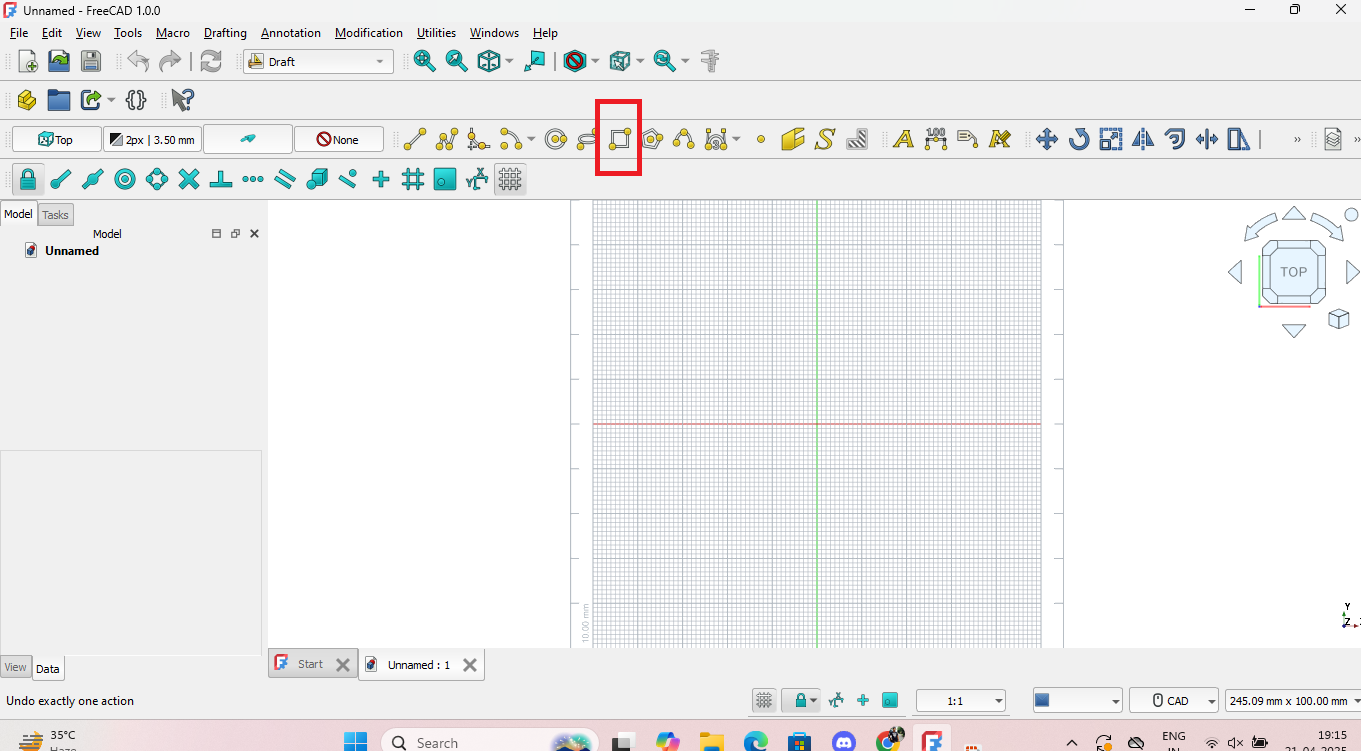
I used the rectangle tool in the Draft workbench to create a rough-sized rectangle. I clicked the first corner point and then the opposite corner to complete the shape. The rectangle appeared on the grid, and I could see its dimensions in the property panel. Although the size wasn’t exact, it gave me a basic shape to start with. This rough rectangle serves as the base outline, which I can later edit or constrain precisely for my Fab Academy design.
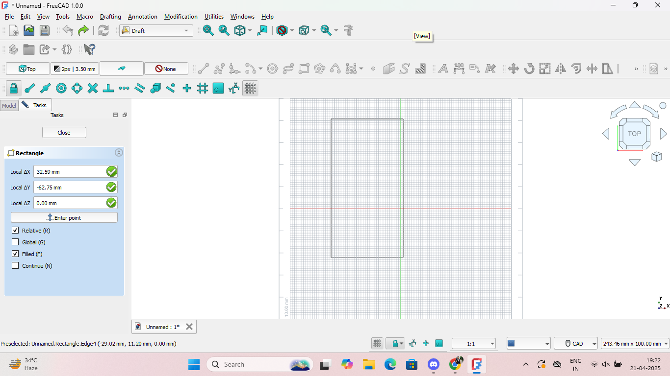
i drag the rectangle in my freecad work area and mark the dimension required in the side box. then the rectangle is created in 2d vector file.we can generate any design and dimension based on our design in vector 2d.
3.3D Modelling, Rendering, animate, simulation.
I select Blender as Modelling tool Graphics software tool set that runs on Windows, macOS, BSD, Haiku, IRIX and Linux. It is used for creating animated films, visual effects, art, 3D-printed models, motion graphics, interactive 3D applications, and virtual reality. It is also used in creating video games.
I planned to create a 3D model of a dog using block-based modeling techniques in Blender 3D, a powerful open-source 3D creation tool. My goal was to design the dog using simple geometric shapes, primarily cubes and rectangular blocks, to give it a stylized, low-poly appearance. This approach makes it easier to model and manipulate each part of the dog—like the body, legs, head, and tail—while maintaining a clean and structured design. Working in Blender allowed me to understand basic modeling tools such as extrusion, scaling, and alignment, which are essential for building more complex 3D forms later.
I Plan a 3d model of Dog build by block in blender 3D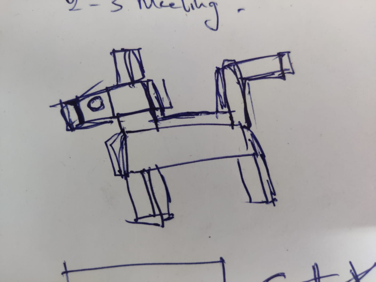
I started working in Blender to bring my design idea to life, based on what I had decided to create. After finalizing the concept, I began by setting up the basic layout and familiarizing myself with Blender’s interface and tools. This included using functions like object creation, scaling, and positioning to shape the initial blocks for my model. Starting with a clear plan made it easier to stay focused and follow a structured workflow. This hands-on experience helped me better understand 3D modeling techniques and gave me confidence in using Blender for future digital design and fabrication projects
I opened Blender 3.6 and was greeted with the default startup screen. From there, I selected the General option, which provided me with a basic workspace setup that includes a default cube, camera, and light. This is the standard starting point for most modeling projects in Blender. The General layout is ideal for beginners because it offers a clean environment with essential tools for 3D modeling, animation, and rendering. This screen marks the beginning of the creative process, where I can now start modifying objects, adding new shapes, and building the structure for the project I planned to create.
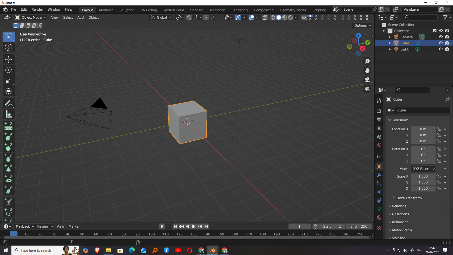
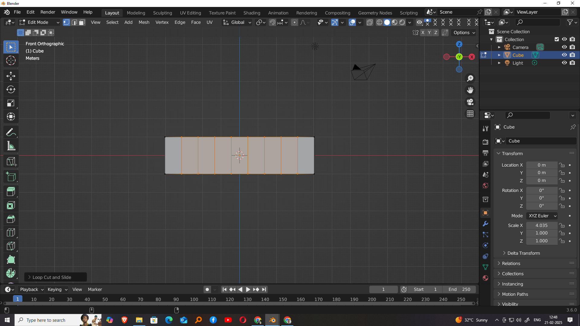
Once Blender opened and I selected the General workspace, a default square cube appeared in the center of the scene. In Object Mode, I selected the cube and used the scale tool to stretch it along the X-axis, giving it a rectangular shape. This helped form the base structure for my model. After adjusting the shape, I switched to Edit Mode to make more detailed changes. In Edit Mode, I selected the appropriate face or edge and used the subdivide tool specifically along the X-axis to create additional segments, which allowed for more precise editing and better control over the shape.
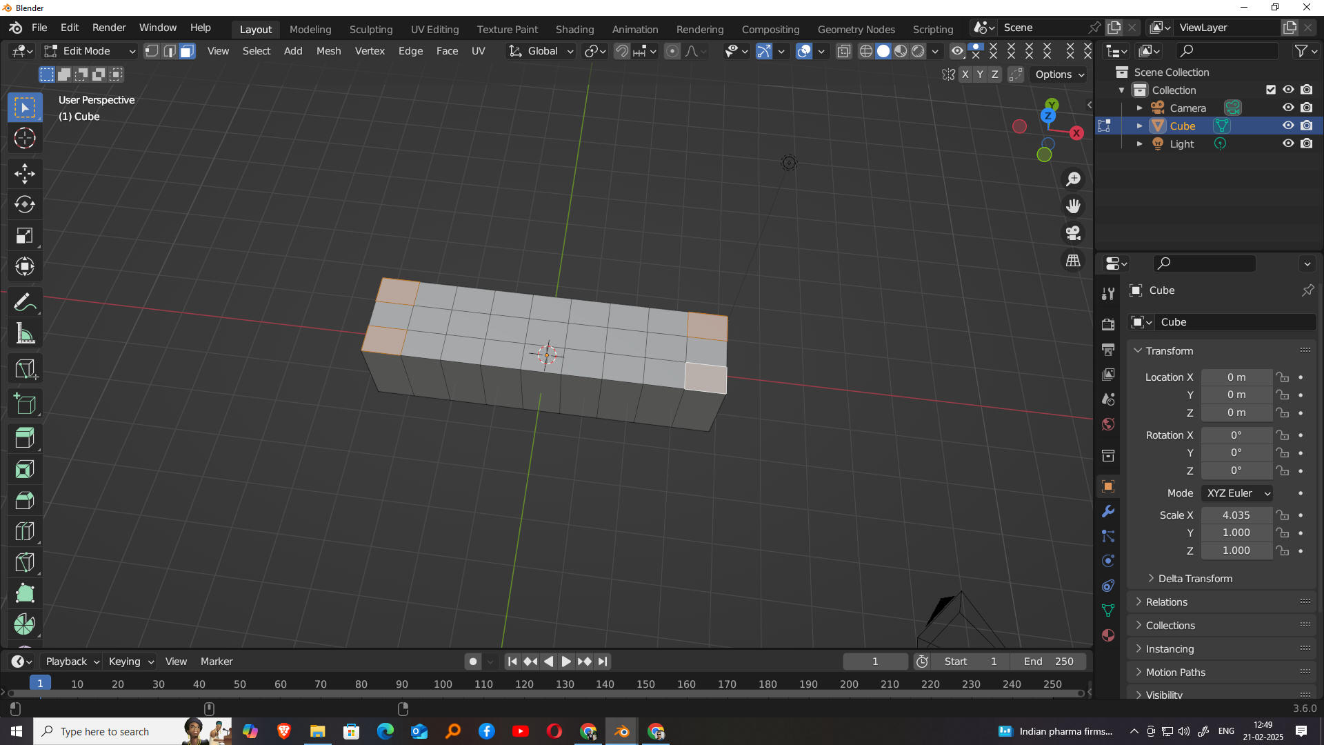
After subdividing the cube along the X-axis in Edit Mode, I proceeded to further refine the geometry by applying subdivision along the Y-axis as well. This step added additional vertical segments to the model, allowing for more detailed manipulation of the shape. By creating a grid of smaller faces through subdivision in both X and Y directions, I gained greater flexibility in shaping the object’s surface. This is especially useful when modeling block-based designs, as it provides more control points for adjusting specific areas of the model and building a more defined, complex structure as the project progresses.
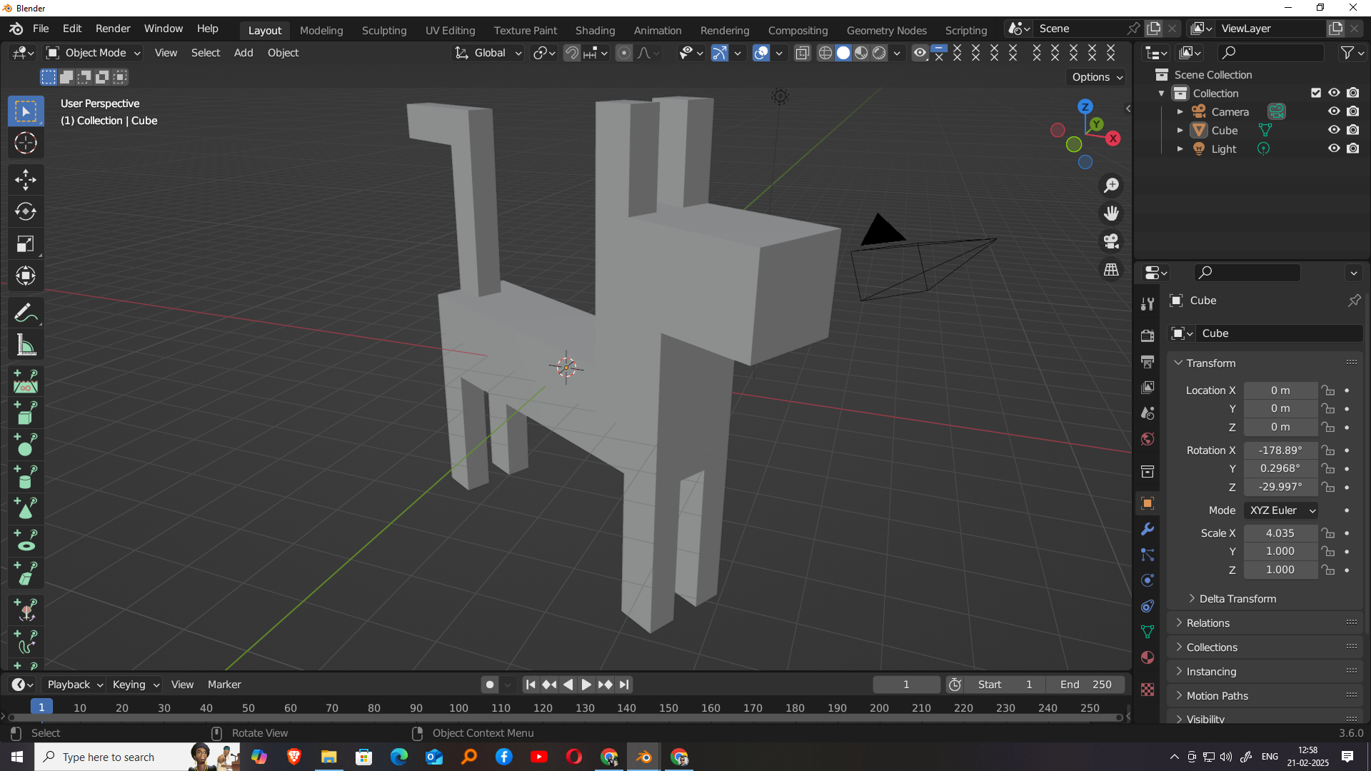
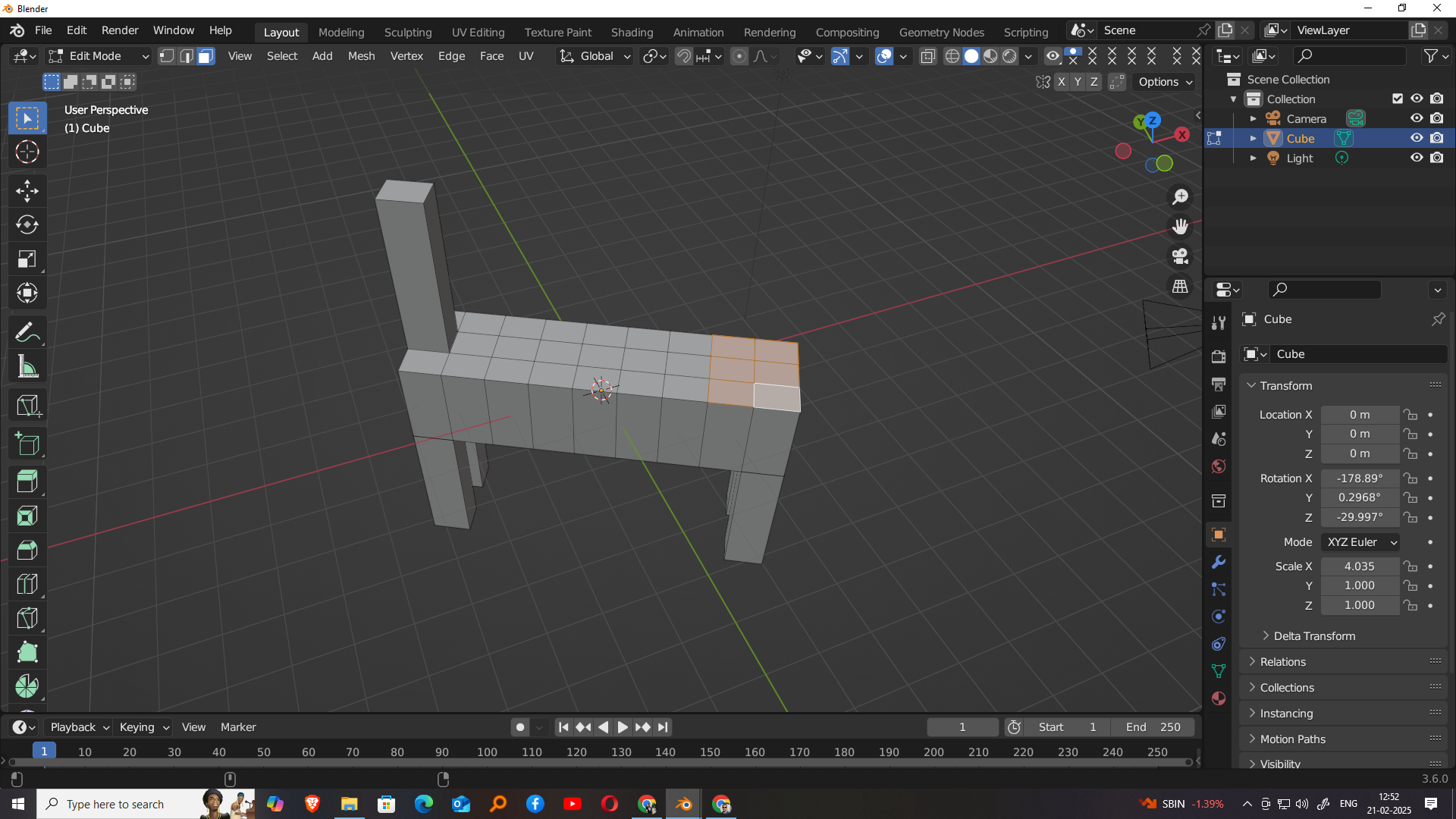
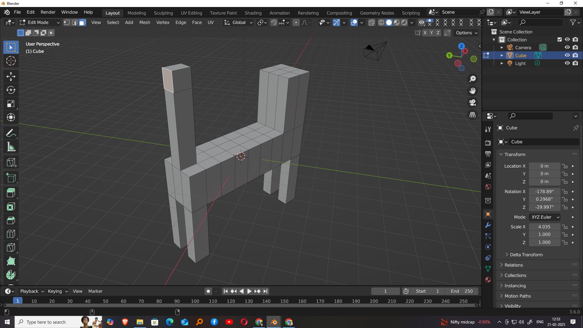
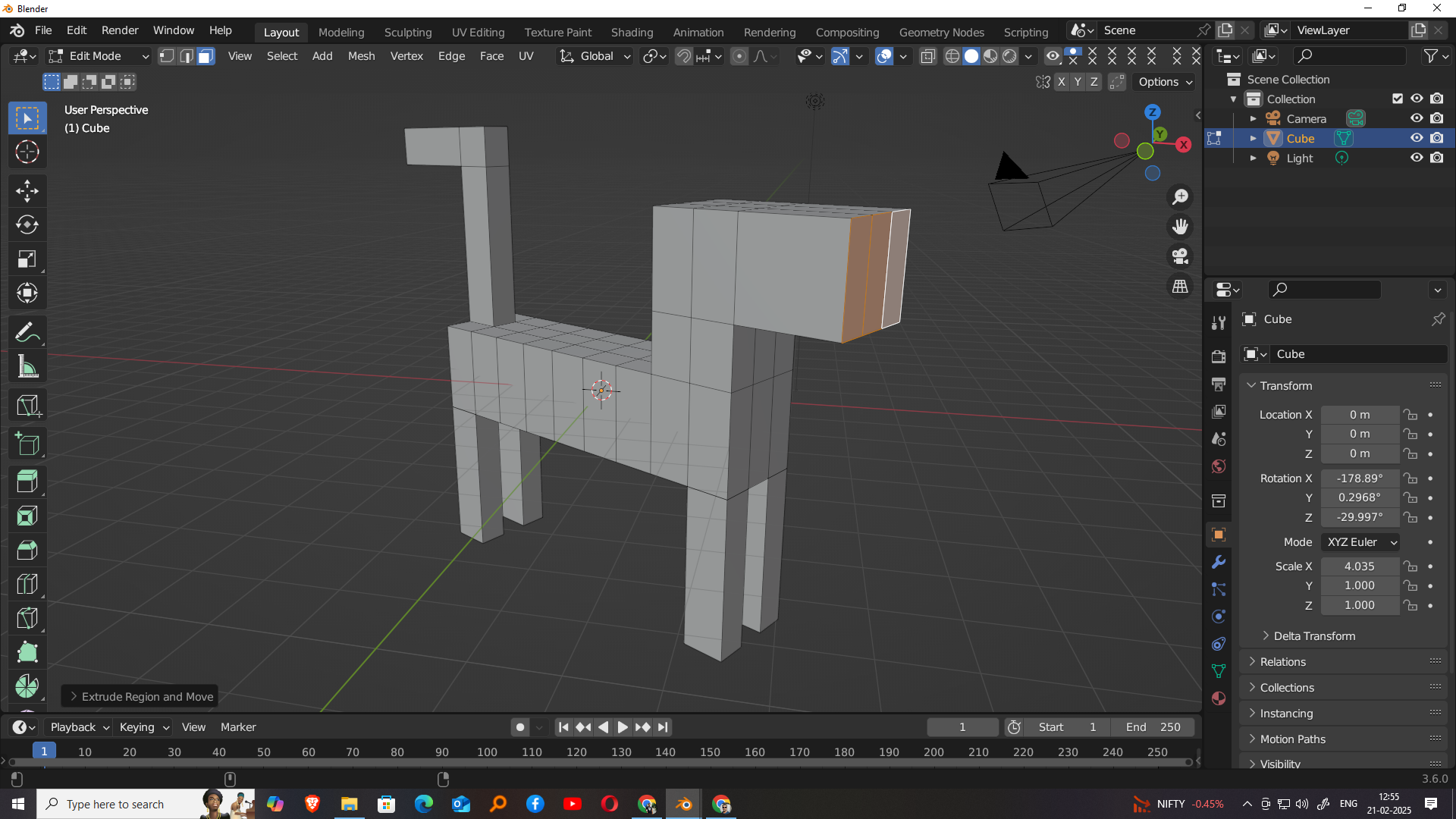
After subdividing the cube along both the X-axis and Y-axis, I selected the four subdivided corners of the shape and used the extrude tool to pull them down. This action formed the four legs of the model, giving it a more defined structure. Next, I focused on the top front section of the cube. I selected the center division of the top face and extruded it upwards to create the neck. This step helped shape the body of the dog and establish its basic form. The extrusions allowed for easy manipulation and provided a foundation for further detailing
After forming the neck, I moved on to shaping the tail of the model. I selected the back center subdivision on the top rear face of the mesh in Edit Mode. Using the extrude tool, I pulled this section outward to form the tail of the dog. This extrusion gave the model a more complete and recognizable silhouette. By carefully adjusting the length and angle of the extrusion, I was able to create a simple, blocky tail that matched the overall low-poly style of the model. This step completed the basic structure of the dog using Blender’s modeling tool.
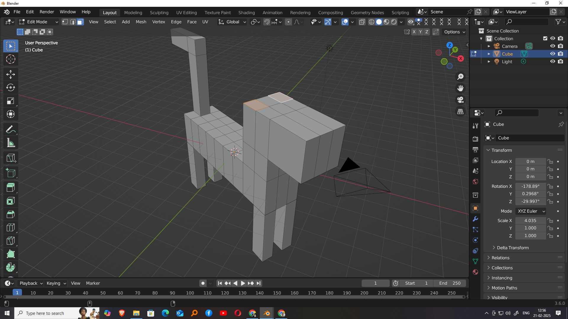
To add more detail to the model, I selected the top face of the tail and used the extrude tool along the Y-axis to create a tail bend, giving it a more natural and dynamic look. This slight curve enhanced the overall shape while maintaining the blocky style. Then, I moved to the front of the neck, where I selected the appropriate face and extruded it along the Y-axis to form the head. This extrusion extended the geometry forward, creating the basic shape of the dog's head and completing the primary structure of the model in Blender.
To add more detail to the head of the model, I first subdivided the head section to create additional geometry for finer control. Then, I selected the two top corners of the head—one on each side—and used the extrude tool along the Z-axis to pull them upward, forming the ears of the dog. This step gave the model a more recognizable and expressive appearance while keeping the block-style aesthetic consistent. The extruded ears added character and depth to the model, making it look more complete and helping distinguish the head from the rest of the body.
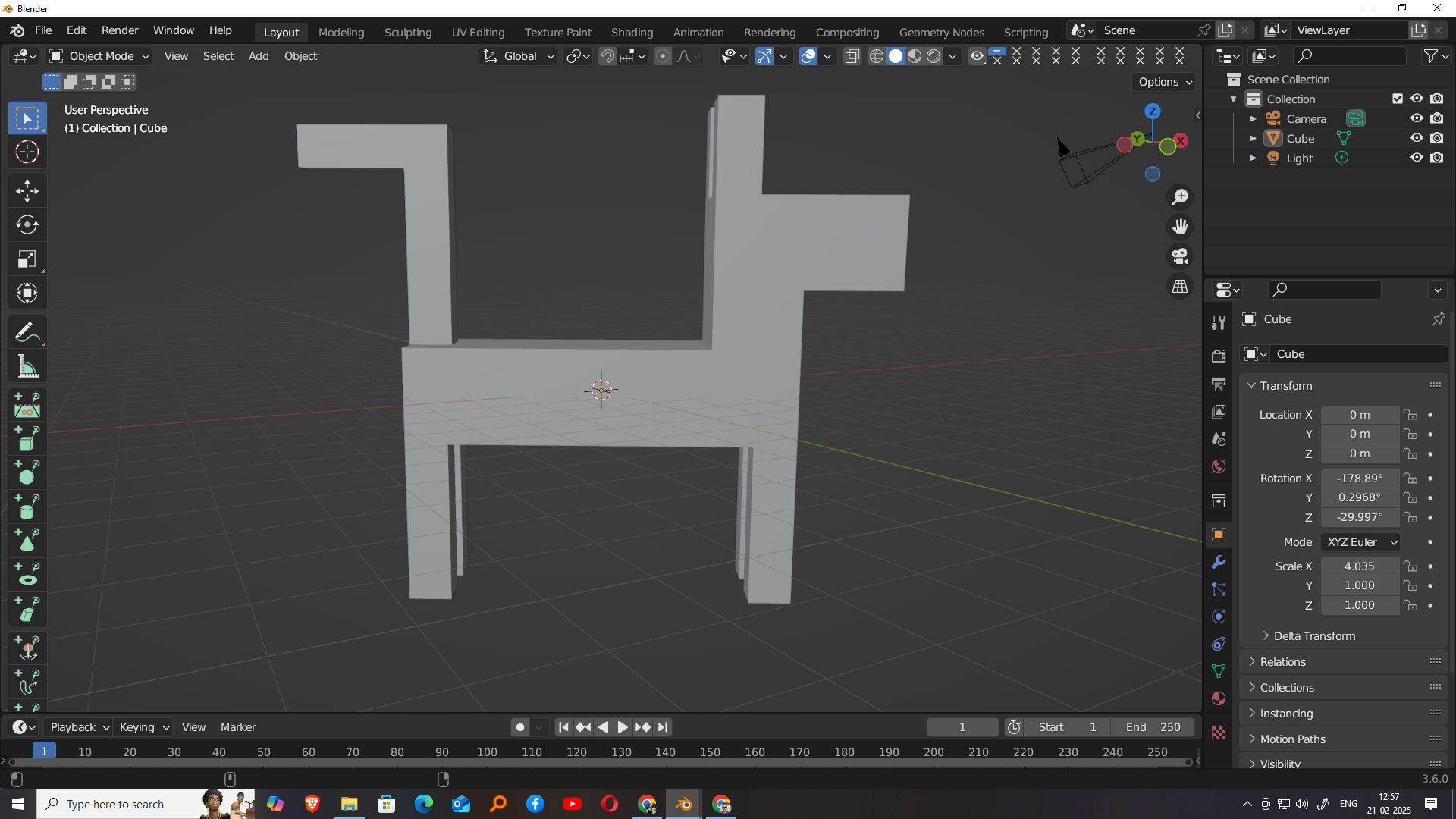
Thus, I successfully completed my 3D model, designed entirely using basic block modeling techniques in Blender. The model represents a stylized dog, constructed by extruding and shaping a simple cube through a series of well-planned steps, including forming the body, legs, neck, tail, head, and ears. Each part was carefully adjusted to maintain a clean, low-poly appearance suitable for 3D printing. This project helped me understand essential modeling tools such as scaling, subdivision, extrusion, and axis control. With the final structure complete and properly proportioned, the model is now ready to be exported and prepared for the 3D printing process.
Rendering
Rendering is the process of converting a 3D scene into a 2D image, allowing the visual representation of the model to be finalized. It involves complex calculations of lighting, shadows, reflections, materials, and camera positioning to produce a realistic or stylized output. In Blender, there are two primary rendering engines: Cycles and Eevee. Cycles is a path-tracing engine known for its high-quality, photorealistic renders, ideal for final outputs. On the other hand, Eevee is a real-time render engine that provides faster previews and outputs, making it suitable for quick visualization and animations where speed is a priority.
Sampling
Sampling in rendering refers to the number of rays or calculations used per pixel to determine the final image quality. In Blender, especially when using the Cycles render engine, higher sampling means more accurate lighting, shadows, and material reflections, resulting in a cleaner and more realistic image. However, higher samples also increase render time. Lower sampling can speed up the process but may introduce noise or graininess in the image. Blender allows users to control the number of samples for both preview and final renders, enabling a balance between performance and quality depending on the needs of the project.
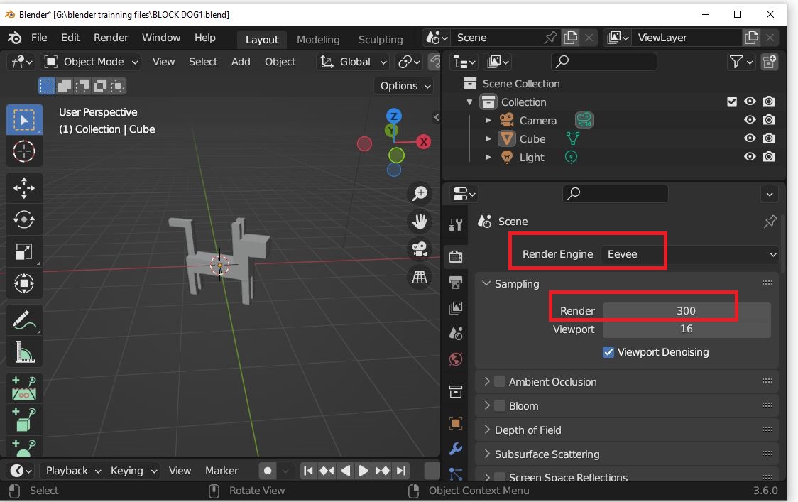
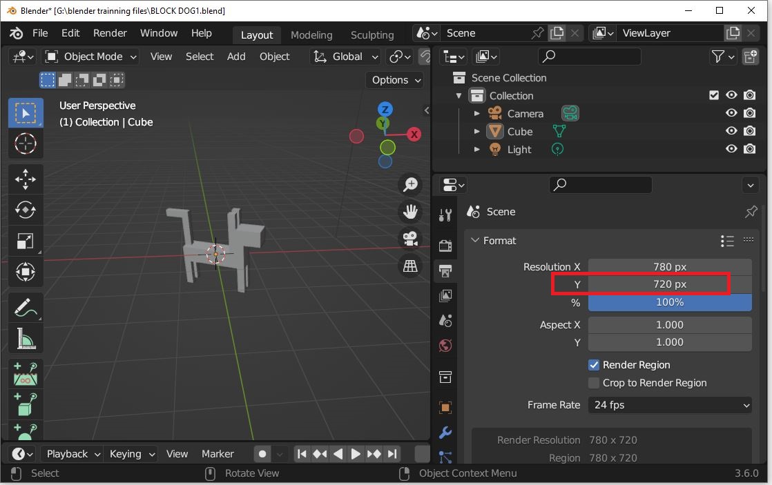
Render 300
For my final render, I set the sampling value to 300 in Blender using the Cycles render engine. This means that for each pixel in the image, Blender calculates the lighting and shading information using 300 samples, which helps produce a much cleaner and more detailed render with minimal noise. Choosing 300 samples strikes a good balance between image quality and render time, especially for still images where a more refined look is required. This setting allowed me to showcase my 3D model with improved lighting accuracy, shadows, and material definition, giving the final output a more polished appearance.
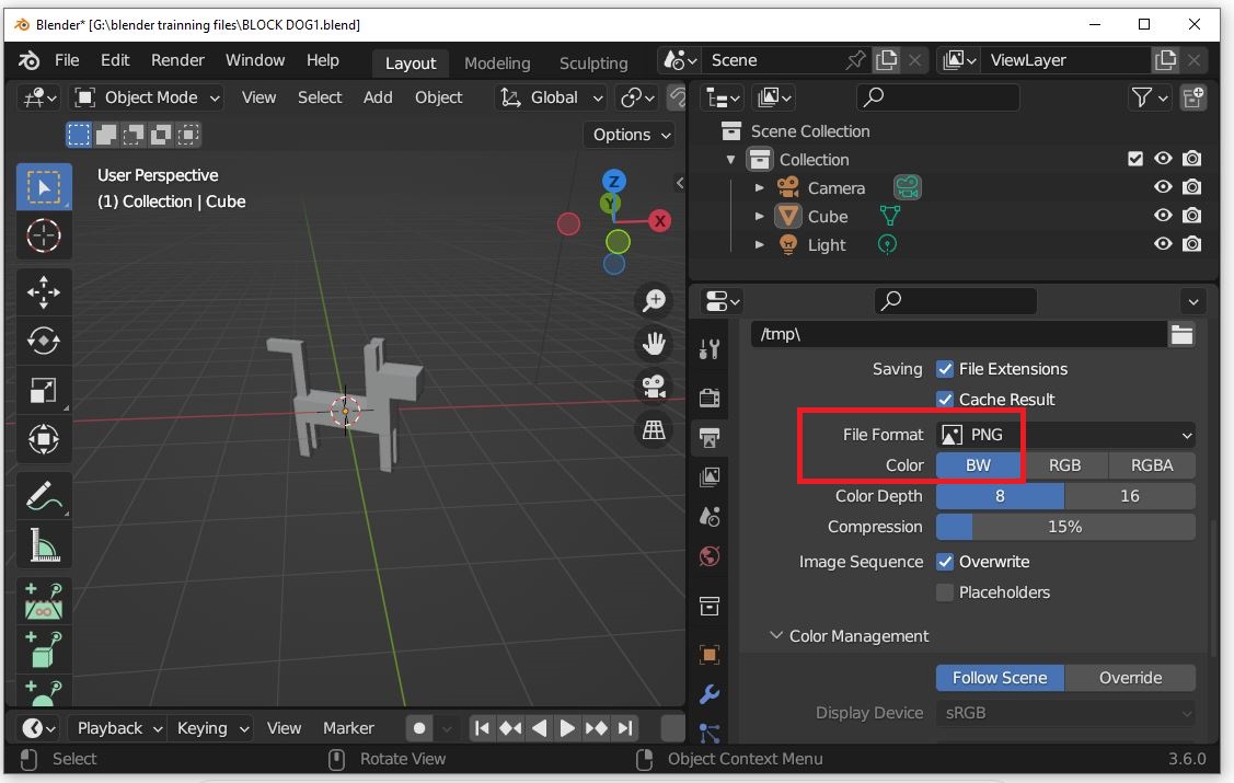
For the final appearance of my 3D model, I chose a black and white color scheme. This minimalistic approach gives the model a clean and bold aesthetic, emphasizing its blocky structure and geometric form without distraction from bright or complex colors. In Blender, I assigned a black material to the main body and used white for specific parts like the legs, ears, or tail to create contrast and highlight different sections. This simple palette not only aligns with the low-poly style but also ensures the model remains visually striking when rendered or prepared for 3D printing.
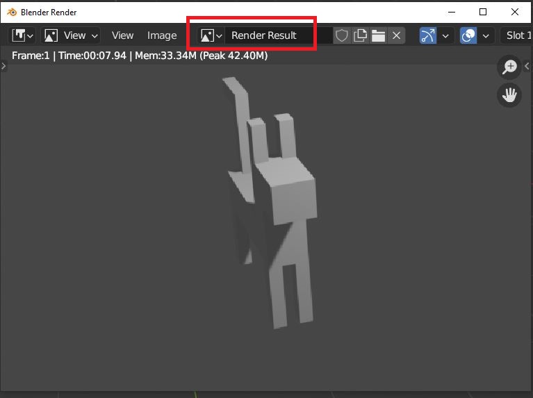
The final output of my project is a block-style 3D dog model, fully designed and rendered using Blender 3.6. The model features distinct body parts like legs, neck, tail, head, and ears—all shaped through subdivision and extrusion techniques. I used a black and white color scheme to give the model a clean and stylized look. The render was done using the Cycles engine with 300 samples to ensure clarity and reduced noise. This final result reflects my understanding of basic 3D modeling, rendering, and design aesthetics, and it’s now ready for presentation or 3D printing.
Rendering Result
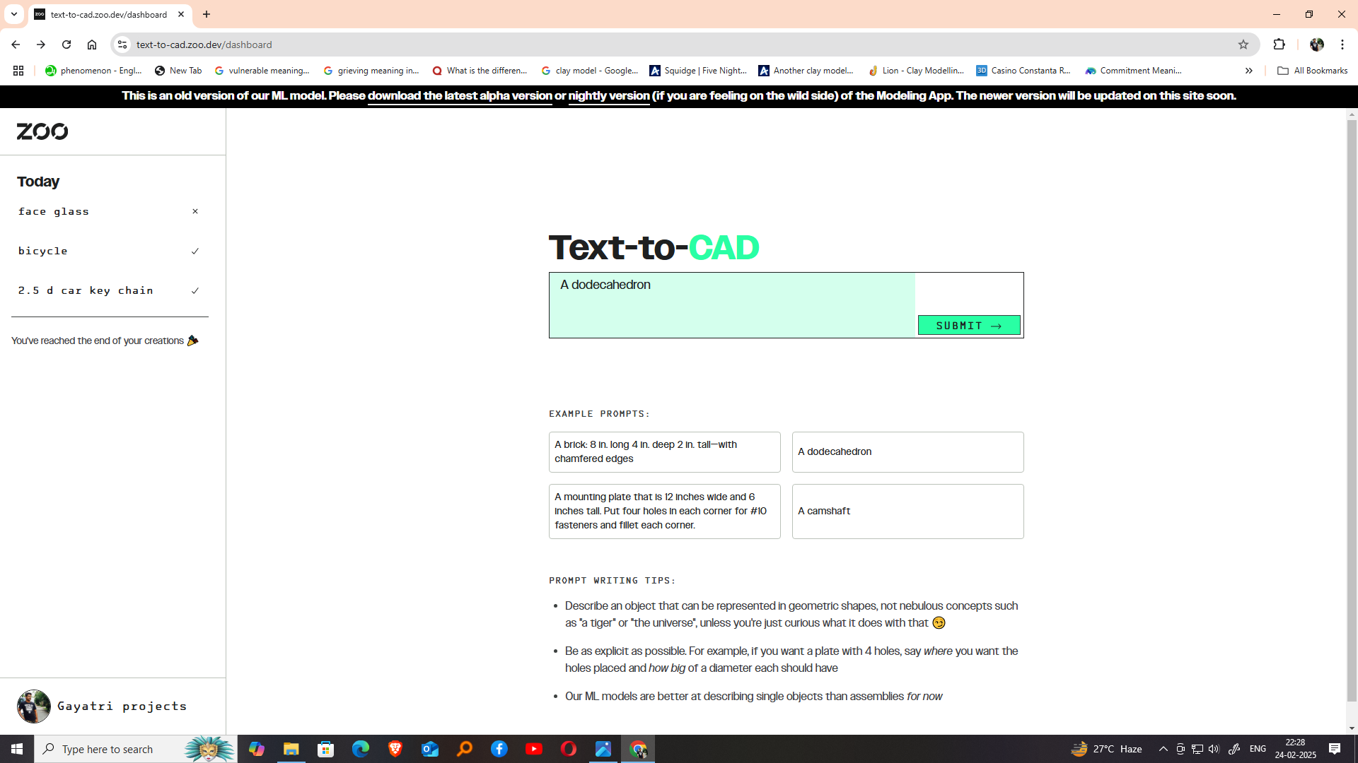
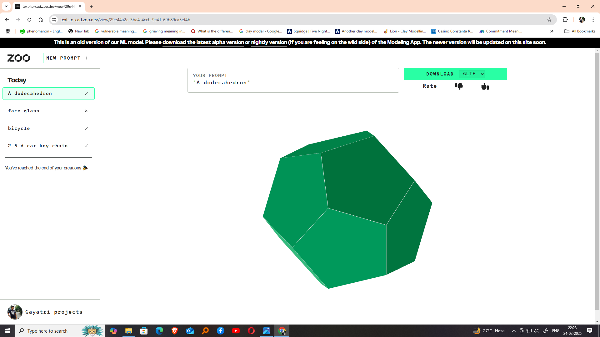
I tried text to 3d model zoo.dev
Zoo.dev is an online platform that offers a wide collection of 3D models available for free or under open licenses. It is designed for creators, developers, and makers looking to integrate 3D content into their projects, whether for digital fabrication, animation, gaming, or virtual environments. For Fab Academy students like me, Zoo.dev is a valuable resource to explore and download models that can be used in laser cutting, 3D printing, CNC machining, or other digital fabrication processes.
I start, I visited the Zoo.dev website and browsed through various categories such as animals, tools, characters, and mechanical parts. The platform’s interface is clean and easy to navigate, allowing users to preview models in 3D directly on the browser. Each model page includes useful information such as file format (commonly STL, OBJ, or glTF), licensing details, file size, and creator credits.
After selecting a model, I downloaded it in STL format, which is compatible with FreeCAD and other modeling software. I then imported it into FreeCAD to view and edit the geometry based on my project needs. These ready-made models save time and help in learning modeling techniques by reverse-engineering or customizing existing designs.
Zoo.dev supports community collaboration by allowing users to upload their own models and share them with others. This aligns perfectly with the open-source and collaborative spirit of Fab Academy. Additionally, using Zoo.dev encourages responsible digital making by respecting licenses and giving credit to creators.
Overall, Zoo.dev is a practical and inspiring tool for exploring 3D models. It helps students and makers quickly access quality assets, experiment with designs, and bring creative ideas to life using digital fabrication technologies. I highly recommend it as part of any Fab Academy research or development
Reflection
During this assignment, I explored several CAD software tools, including Text-CAD, FreeCAD, blender. While I have used different software based on the requirements of each project. For this particular assignment, I enjoyed working with Blender the most, as it provided a creative and flexible approach to 3D modeling and allowed me to explore new design possibilities. This experience helped me understand the strengths of different CAD tools and how selecting the right software for a specific task can improve both the design process and the final outcome.
Although I enjoyed exploring Blender and used it for fun during this assignment, SolidWorks remains my preferred CAD software. Throughout the Fab Academy course, I plan to use SolidWorks extensively for mechanical design because of its powerful parametric modeling and engineering capabilities. Blender helped me develop creative 3D modeling skills, while SolidWorks will be my primary tool for designing and fabricating functional mechanical projects.
Softwares used
text-cadFreeCAD
Blender