
Interface and application programming
Hero Shot

Summary
Throughout this week, I moved from simple serial communication to interactive GUI development, and finally to advanced robotics interfacing using ROS. Each step built upon the previous one, allowing me to:
- Understand how to control and visualize hardware states.
- Build useful and intuitive interfaces.
- Experiment with real-time data acquisition and simulation.
The group assignment Page :
Work Process Detail
1. Arduino Serial Communication – Basic Control
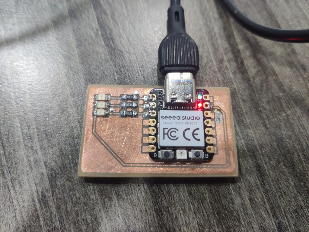
To begin with, I used the Arduino IDE to perform basic serial communication. I connected three LEDs to a board I designed during the Input/Output week. Using simple serial commands sent from the Serial Monitor, I could:
- Turn ON/OFF individual LEDs by typing commands like
LED1_ON,LED2_OFF, etc.
- Control all three simultaneously with multi-command inputs.
// Define LED pins
const int led1 = 26;
const int led2 = 27;
const int led3 = 28;

void setup() {
  // Initialize LED pins as outputs
  pinMode(led1, OUTPUT);
  pinMode(led2, OUTPUT);
  pinMode(led3, OUTPUT);

  // Start serial communication
  Serial.begin(9600);
  Serial.println("Send commands like: LED1 ON");
}

void loop() {
  if (Serial.available()) {
    String command = Serial.readStringUntil('\n'); // Read incoming command
    command.trim(); // Remove extra whitespace

    if (command == "LED1 ON") {
      digitalWrite(led1, HIGH);
    } else if (command == "LED1 OFF") {
      digitalWrite(led1, LOW);
    } else if (command == "LED2 ON") {
      digitalWrite(led2, HIGH);
    } else if (command == "LED2 OFF") {
      digitalWrite(led2, LOW);
    } else if (command == "LED3 ON") {
      digitalWrite(led3, HIGH);
    } else if (command == "LED3 OFF") {
      digitalWrite(led3, LOW);
    } else {
      Serial.println("Invalid command");
    }
  }
}
This was a straightforward and effective way to test basic communication between a PC and microcontroller using Serial.print() and Serial.read() functions.
2. Processing IDE – Graphical User Interface
Moving to a slightly more advanced setup, I used Processing IDE to create a simple GUI for serial control:
- The interface contained six buttons, each corresponding to ON/OFF states for three LEDs.
- Clicking a button would send a serial command to the Arduino to control the LED state.
Arduino Code:
const int led1 = 26;
const int led2 = 27;
const int led3 = 28;

void setup() {
  pinMode(led1, OUTPUT);
  pinMode(led2, OUTPUT);
  pinMode(led3, OUTPUT);
  Serial.begin(9600);
}

void loop() {
  if (Serial.available()) {
    String command = Serial.readStringUntil('\n');
    command.trim();

    if (command == "LED1 ON") digitalWrite(led1, HIGH);
    else if (command == "LED1 OFF") digitalWrite(led1, LOW);
    else if (command == "LED2 ON") digitalWrite(led2, HIGH);
    else if (command == "LED2 OFF") digitalWrite(led2, LOW);
    else if (command == "LED3 ON") digitalWrite(led3, HIGH);
    else if (command == "LED3 OFF") digitalWrite(led3, LOW);
  }
}
Processing Code:
import processing.serial.*;


Serial myPort;

Button[] buttons = new Button[6];
String[] labels = {
  "LED1 ON", "LED1 OFF",
  "LED2 ON", "LED2 OFF",
  "LED3 ON", "LED3 OFF"
};

void setup() {
  size(400, 300);
  println(Serial.list());
  // Change the index [0] to your correct port from the list
  myPort = new Serial(this, Serial.list()[2], 9600);

  for (int i = 0; i < 6; i++) {
    buttons[i] = new Button(50 + (i % 2) * 150, 50 + (i / 2) * 70, 120, 50, labels[i]);
  }
}

void draw() {
  background(240);
  for (Button b : buttons) {
    b.display();
  }
}

void mousePressed() {
  for (Button b : buttons) {
    if (b.isClicked(mouseX, mouseY)) {
      myPort.write(b.label + "\n");
      println("Sent: " + b.label);
    }
  }
}

class Button {
  float x, y, w, h;
  String label;

  Button(float x, float y, float w, float h, String label) {
    this.x = x;
    this.y = y;
    this.w = w;
    this.h = h;
    this.label = label;
  }

  void display() {
    fill(200);
    rect(x, y, w, h);
    fill(0);
    textAlign(CENTER, CENTER);
    text(label, x + w/2, y + h/2);
  }

  boolean isClicked(float mx, float my) {
    return mx > x && mx < x + w && my > y && my < y + h;
  }
}
The goal was to create a graphical interface using Processing that allows the user to control three LEDs connected to an Arduino by clicking ON/OFF buttons.
What the UI Includes:
- A canvas sized 400x300 pixels
- Six buttons: ON and OFF for each of the three LEDs
- Clear labels like
"LED1 ON"and"LED1 OFF"for user interaction
- Each button sends a serial command to the Arduino when clicked
How It Works (Processing Code):
Button[] buttons = new Button[Creates an array of 6 custom Button objects for the 6 actions.
myPort = new Serial(this, Serial.list()[2], 9600);Initializes serial communication between Processing and Arduino.
void draw() { ... }Renders all buttons on the canvas.
void mousePressed() { ... }Detects which button was clicked and sends the corresponding command (like "LED1 OFF\n") over serial to the Arduino.
Arduino Side:
if (Serial.available()) {
  String command = Serial.readStringUntil('\n');
  ...
}
Waits for a complete command string sent via serial, terminated by a newline character.
if (command == "LED1 ON") digitalWrite(led1, HIGH);Parses the command and performs the appropriate action for each LED.
GPIO Pin Assignments:
const int led1 = 26;
const int led2 = 27;
const int led3 = 28;
Defines the digital pins used to control the LEDs, and sets them as output in setup().
Communication Flow:
- The user clicks a button in Processing.
- The button’s label (e.g.,
"LED3 ON") is sent as a string over serial.
- The Arduino reads the string, interprets it, and toggles the corresponding LED.
Input Device Interface:
I expanded this concept by integrating the Hall effect sensor (from the Input Devices week):
- The interface displayed a dynamic bar graph that updated in real-time based on the proximity and polarity of a magnet.
- This gave me an interactive visual output based on analog input from the sensor.
Arduino Code:
const int sensorPin = A0;

void setup() {
  Serial.begin(9600);
}

void loop() {
  int sensorValue = analogRead(sensorPin); // range: 0–1023
  Serial.println(sensorValue);
  delay(10); // smooth data flow
}
Processing Code:
import processing.serial.*;

Serial myPort;
int sensorValue = 0;

void setup() {
  size(500, 200);
  println(Serial.list());
  myPort = new Serial(this, Serial.list()[2], 9600); // change index if needed
  myPort.bufferUntil('\n');
}

void draw() {
  background(255);

  // Draw title
  fill(0);
  textAlign(CENTER);
  text("Hall Sensor Slider", width / 2, 30);

  // Map sensor value to slider width
  float mappedWidth = map(sensorValue, 0, 1023, 0, width - 60);

  // Draw background bar
  fill(220);
  rect(30, 100, width - 60, 30, 10);

  // Draw slider bar
  fill(0, 150, 255);
  rect(30, 100, mappedWidth, 30, 10);

  // Draw value
  fill(0);
  textAlign(LEFT);
  text("Value: " + sensorValue, 30, 90);
}

void serialEvent(Serial p) {
  String input = p.readStringUntil('\n');
  if (input != null) {
    input = trim(input);
    if (input.length() > 0) {
      sensorValue = int(input);
    }
  }
}
The goal was to create a visual real-time feedback interface for a Hall effect sensor connected to the Arduino. The interface is implemented using the Processing IDE, which allows for quick and interactive visualizations.
What the UI Includes:
- A window of size
500 x 200pixels
- A label/title that reads "Hall Sensor Slider"
- A horizontal slider bar that grows based on sensor input
- A numerical display of the current sensor value
Key Components in Processing Code:
size(500, 200);Initializes a drawing canvas 500 pixels wide and 200 pixels high.
rect(30, 100, mappedWidth, 30, 10);Draws a rounded rectangle to visually represent the live value from the sensor. The mappedWidth is calculated using:
map(sensorValue, 0, 1023, 0, width - 60);This line scales the sensorValue (which ranges from 0–1023) to a pixel width suitable for the window.
text("Value: " + sensorValue, 30, 90)Displays the live numeric sensor value above the bar. Arduino Side:
const int sensorPin = A0;Defines the analog input pin connected to the Hall sensor.
int sensorValue = analogRead(sensorPin);
Serial.println(sensorValue);
Reads a value from the Hall sensor and sends it over serial to the computer. The value is sent as a string followed by a newline (\n), making it easy for the Processing side to detect full messages.
delay(10)A short delay to control the data rate and ensure smoother streaming (about 100 readings per second).
Processing Side:
myPort = new Serial(this, Serial.list()[2], 9600);Establishes a serial connection to the Arduino using the correct COM port and baud rate (must match Serial.begin(9600) on the Arduino).
myPort.bufferUntil('\n')Tells Processing to wait for a full line (ending in newline) before calling the serialEvent() function.
void serialEvent(Serial p) {
  String input = p.readStringUntil('\n');
  ...
  sensorValue = int(input);
}
When a new line of data is received, it’s converted from string to integer and stored in sensorValue, which is then used in the draw() loop to update the UI.
3. Robot Operating System (ROS) – Advanced Real-Time Interaction
For the final and most advanced part of the week, I used ROS to interface with two hardware elements:
a. IMU Visualization in ROS
This Tutorial was super helpful: https://automaticaddison.com/tag/bno055/
- I connected an IMU sensor (BNO055) to an Arduino and sent real-time orientation data via serial.
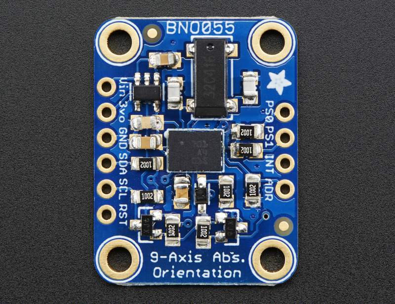
- On the ROS side, I followed the automatic_addison tutorial to parse the serial data and visualize the IMU orientation in RViz.
Arduino Code:
#include <Wire.h>
#include <Adafruit_Sensor.h>
#include <Adafruit_BNO055.h>
#include <ros.h>
#include <sensor_msgs/Imu.h>

Adafruit_BNO055 bno = Adafruit_BNO055(55);

ros::NodeHandle nh;
sensor_msgs::Imu imu_msg;
ros::Publisher imu_pub("imu/data", &imu_msg);

void setup() {
  nh.initNode();
  nh.advertise(imu_pub);

  if (!bno.begin()) {
    while (1); // Failed to initialize
  }

  delay(1000);
}

void loop() {
  imu::Quaternion quat = bno.getQuat();

  imu_msg.orientation.w = quat.w();
  imu_msg.orientation.x = quat.x();
  imu_msg.orientation.y = quat.y();
  imu_msg.orientation.z = quat.z();

  // Leave linear acceleration and angular velocity zero for now
  imu_msg.header.stamp = nh.now();
  imu_msg.header.frame_id = "imu_link";

  imu_pub.publish(&imu_msg);
  nh.spinOnce();
  delay(10);
}
- This enabled me to see the orientation of the IMU in 3D space, mimicking the physical movement.
b. Robot Arm Control (Hardware-in-the-Loop)
This Tutorial was super helpful:https://maker.pro/arduino/tutorial/how-to-control-a-robot-arm-with-ros-and-arduino and this https://howtomechatronics.com/tutorials/arduino/diy-arduino-robot-arm-with-smartphone-control/(Arm CAD )
- I followed a tutorial where a real robotic arm and a virtual arm model were controlled in sync using ROS.
- Commands were sent from joint state publisher node to the simulated robot in RViz and real life, forming a closed feedback loop.
- This was an insightful application of ROS in real-world robotics and demonstrated the power of integrating hardware and simulation.
Learning Outcome
- Developed serial communication skills with Arduino.
- Built interactive GUIs using Processing to control and visualize sensor data.
- Learned how to integrate IMU sensors with ROS and display live data in RViz.
- Understood hardware-in-the-loop concepts with a real and virtual robotic arm.
- Followed structured tutorials and adapted them to custom hardware.