Electronics Fundamentals revision
Summary
we focused on electronics design, reviewing fundamental components like resistors, capacitors, transistors, and voltage dividers while testing circuits using measurement tools. They used a power supply for voltage regulation, a multimeter for circuit analysis, an oscilloscope and function generator to observe waveforms, and a logic analyzer to capture digital signals, including I2C and PWM. Through these hands-on exercises, they improved their circuit debugging skills and gained practical experience in electronics testing and design—and we did it!
The group assignment Page :
Work Process Detail(group assignment)
1. Review of Electronics Fundamentals
Last week, we started the group assignment by reviewing key topics in electronics, such as voltage, current, power, resistors, capacitors, transistors, inductors, diodes, and voltage dividers. We referred to The Art of Electronics book. Below are some notes from our discussion:


2. Testing Measurement Equipment
We tested various measurement tools, including the multimeter, power supply, oscilloscope, and logic analyzer. These instruments are essential for analyzing and troubleshooting electrical circuits, ensuring accurate readings and signal integrity.
Power Supply
We explored the DC power supply "GWINSTEK GPS 3303," which features two channels and an additional channel for parallel connections.

Multimeter and Clamp Meter
A multimeter is a versatile tool used to measure voltage, current, and resistance in electronic circuits.


During our testing, we:
- Measured DC voltage across a DC power supply in both series and parallel configurations.


- Tested various resistor values and potentiometers.
Fixed Resistor:

Resistors in Series:

Potentiometer:


- Checked the voltage divider.


Oscilloscope
The oscilloscope is used to visualize electrical signals in real-time, making it essential for analyzing waveforms.
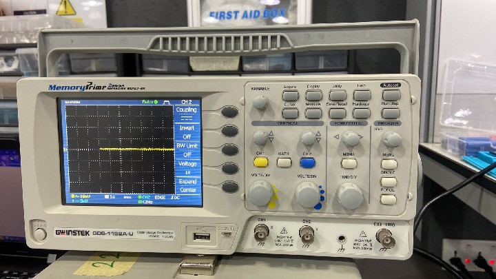
We:
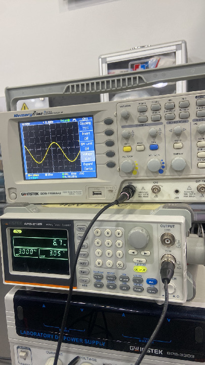
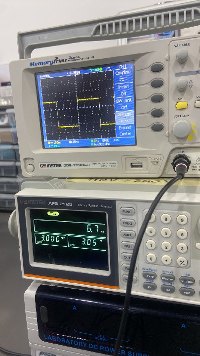
- Observed different signal waveforms, including sine, square, and triangular waves.
- Checked PWM signals by creating a fading LED using XIAO RP2040.
- Tested the digital signal from a blinking LED circuit by changing the delay time and observing the output signal on the oscilloscope.
- Used a potentiometer with the XIAO RP2040 to observe the analog signal from the potentiometer.
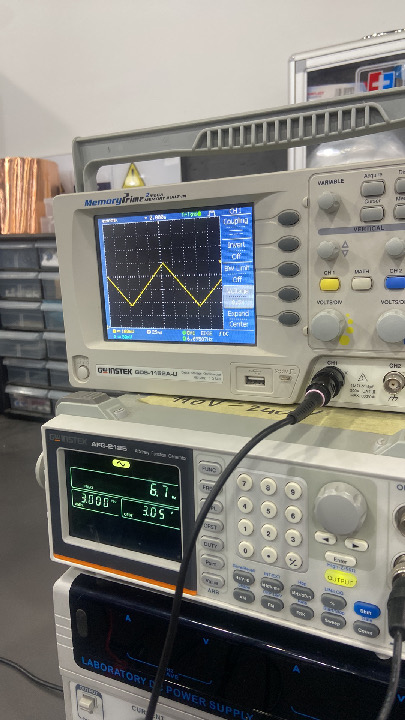
Function Generator
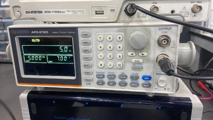
We used a function generator along with the oscilloscope to generate sine, square, and triangle waves.
Logic Analyzer
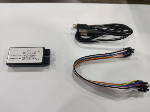
A logic analyzer is used to capture and analyze digital signals in a circuit.
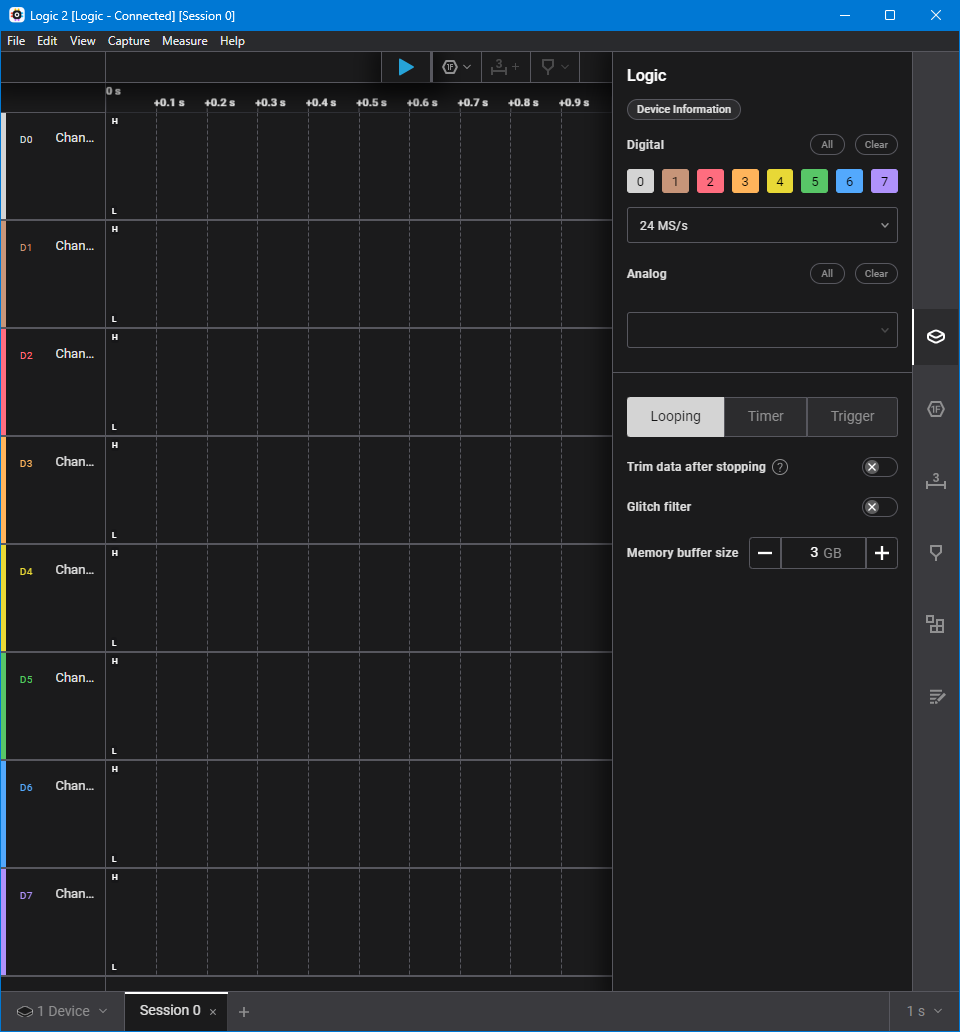
First, we downloaded the Saleae software.

During our testing, we used an Arduino Uno to:
- Test the built-in LED blinking signal.


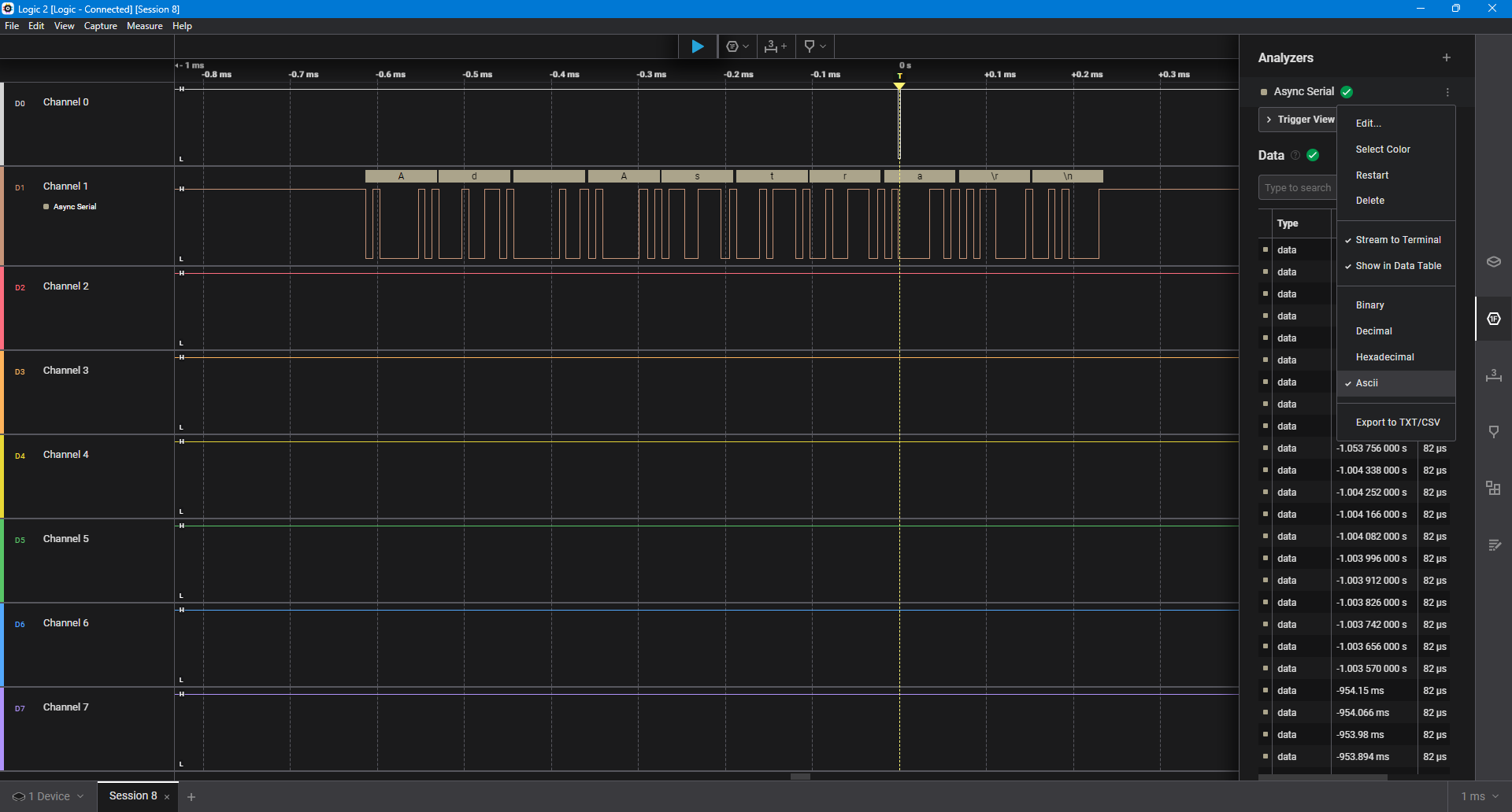
- Analyze serial communication using
Serial.print().


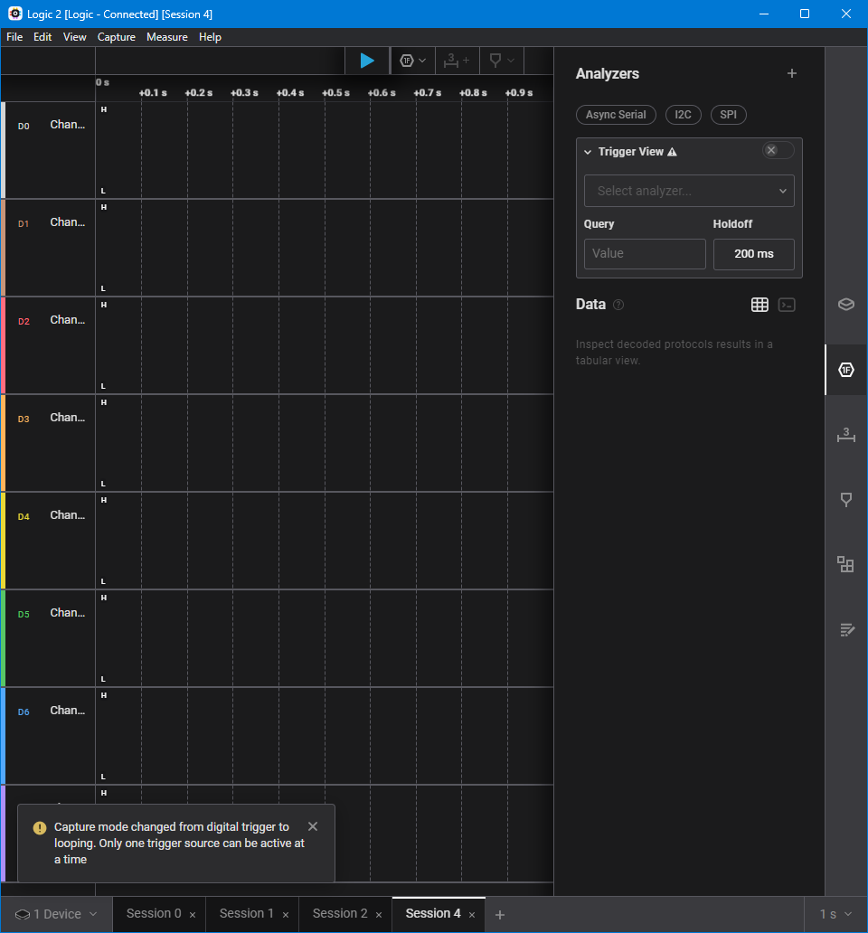
- Analyze the I2C protocol using an Adafruit OLED display.


https://www.saleae.com/pages/downloads
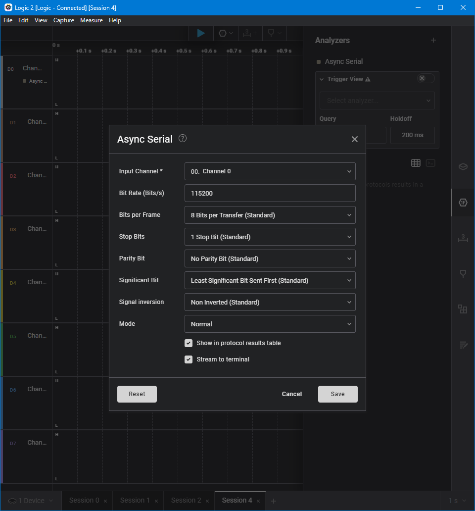
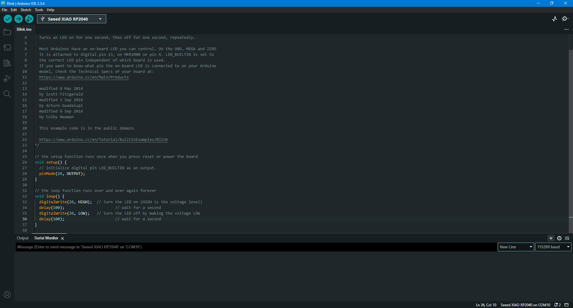
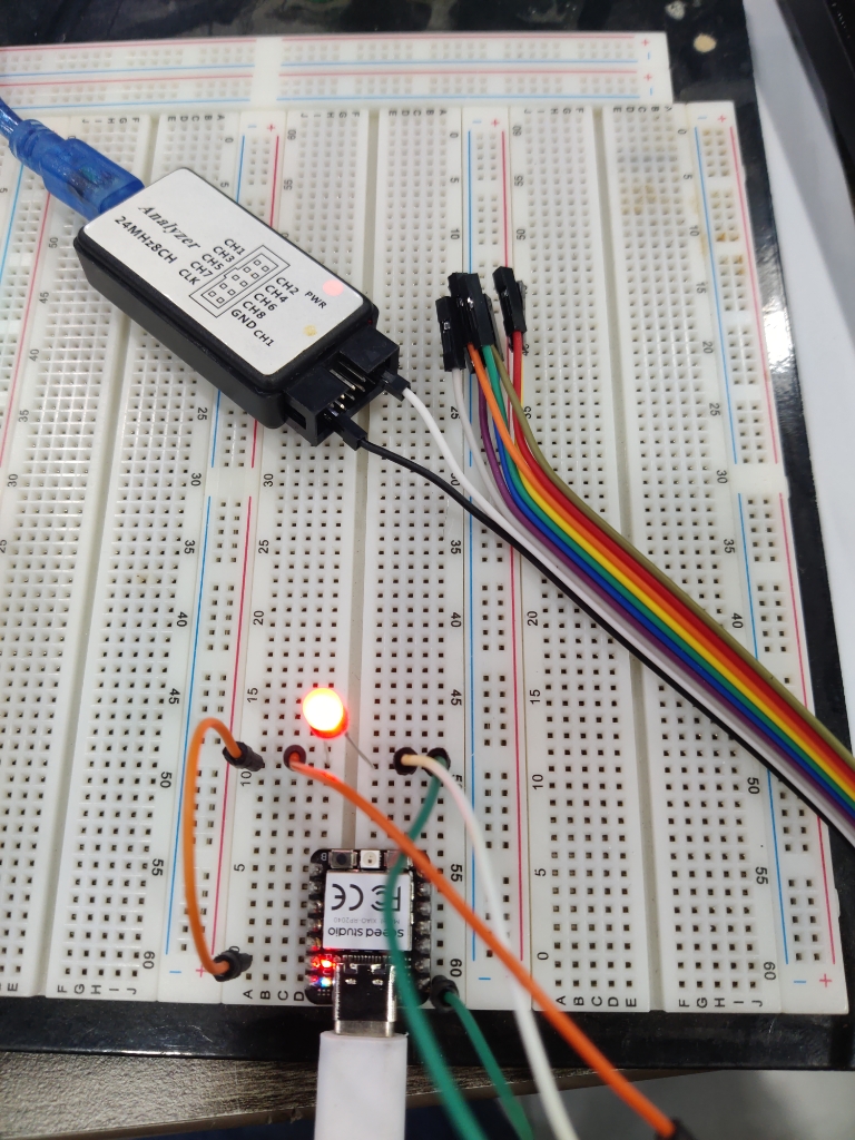
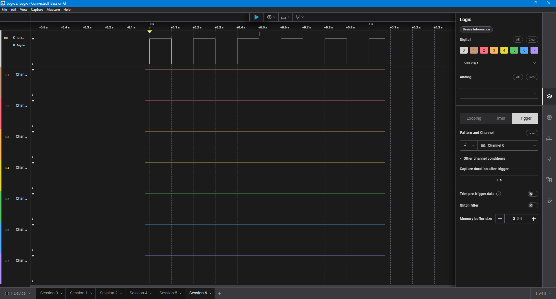
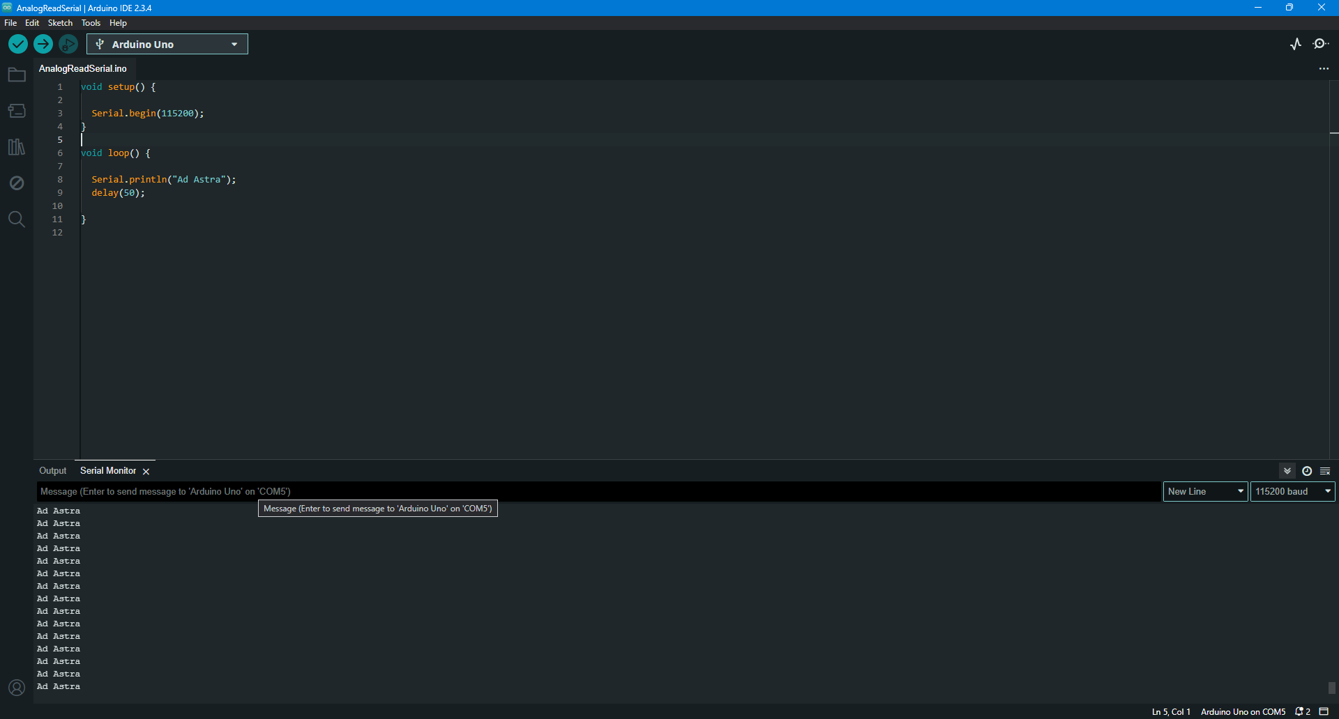
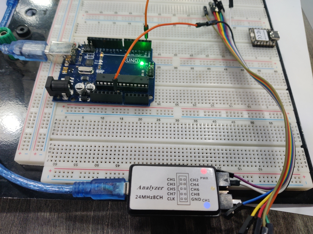
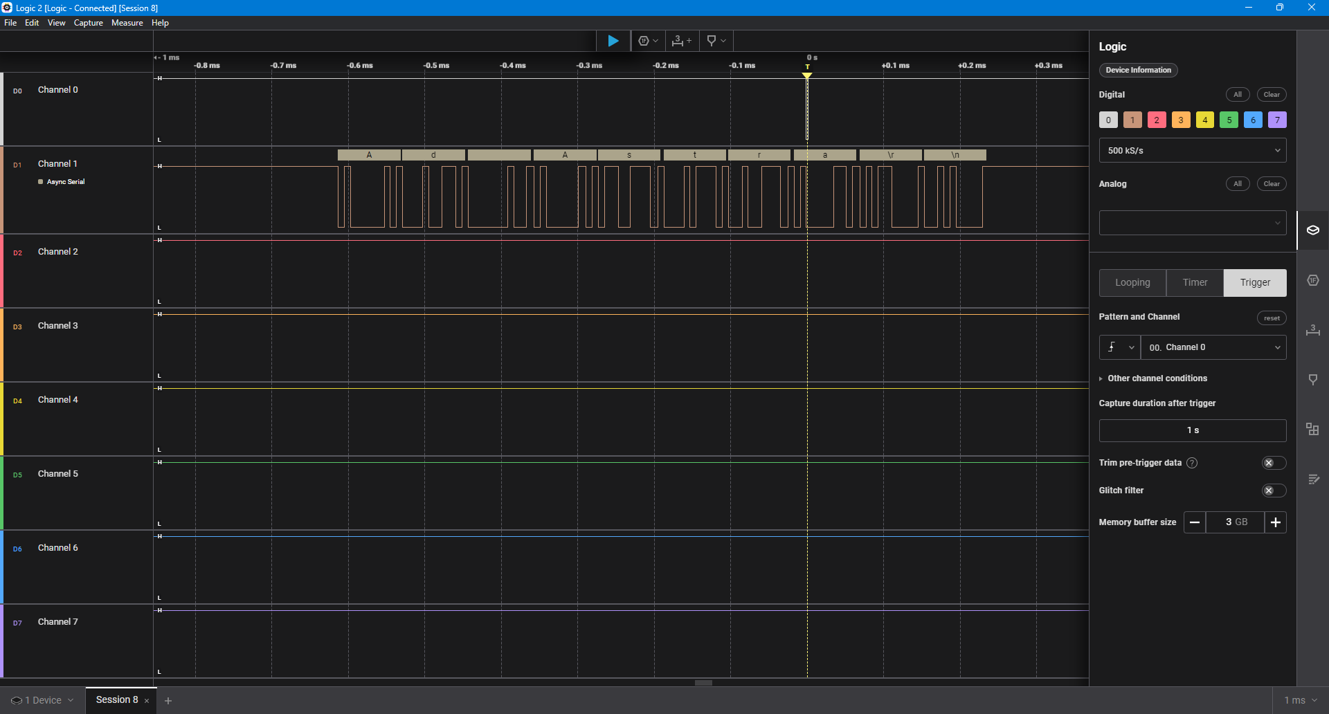
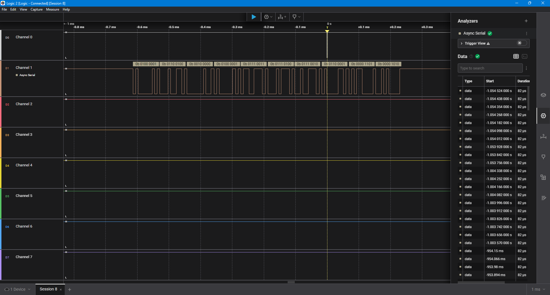
These tests helped us understand how to effectively use each tool for troubleshooting and verifying circuit performance.
Learning Outcome
Through this week's exploration of electronics design and testing, I gained hands-on experience in circuit analysis, debugging, and measurement techniques. I learned how to effectively use power supplies, multimeters, oscilloscopes, function generators, and logic analyzers to evaluate circuit behavior. Understanding waveforms, voltage regulation, and digital signal communication (I2C, PWM) provided deeper insights into microcontroller interactions. This experience strengthened my ability to troubleshoot circuits, interpret electronic signals, and apply measurement tools for future embedded systems and hardware projects.