Construction Kit
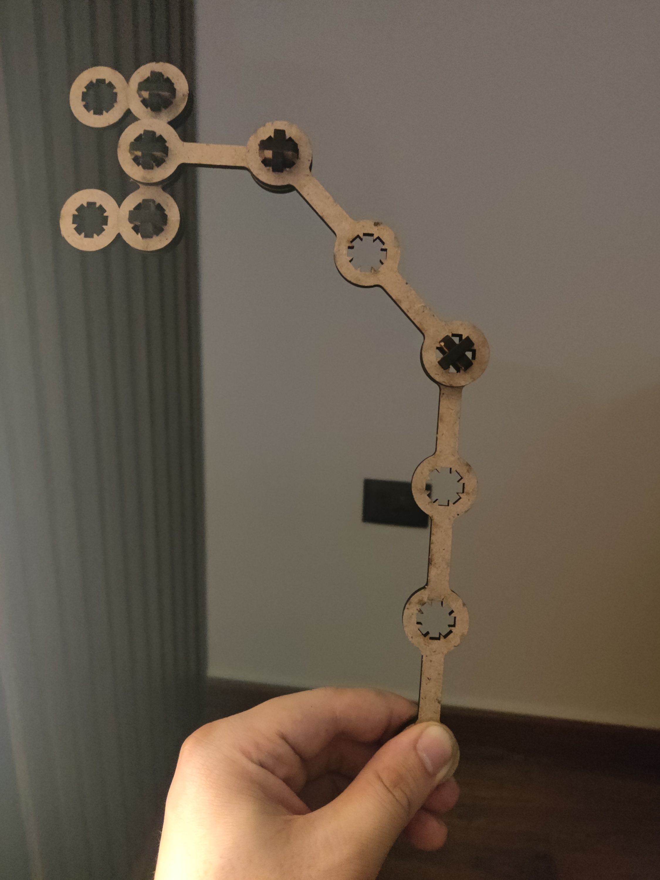
Hero Shot
Summary
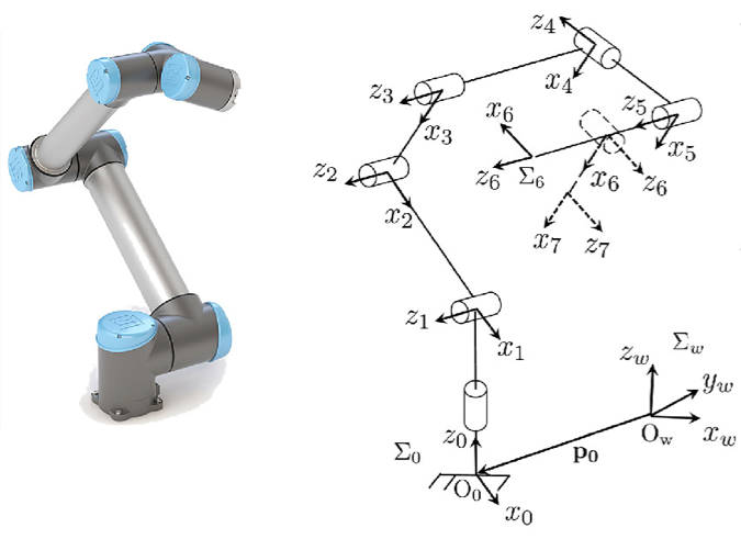
In this project, I designed and built a laser-cut construction kit to help understand the kinematics of robotic arms, focusing on links and joints. Initially, I experimented with basic geometric shapes but found them ineffective.
I then refined my approach using Fusion 360 to create a modular robotic arm with three links and three joints. My first prototype, made from thin MDF, broke easily, highlighting the importance of material selection and calibration.
After adjusting the design and using thicker, reinforced parts, I successfully assembled a functional model that demonstrates robotic motion.
This process deepened my understanding of kinematic principles, laser cutting techniques, and iterative design.
Work Process Detail
Laser-Cut Construction Kit – Step-by-Step Documentation
For this project, I designed a laser-cut construction kit to help understand the kinematics of robotic arms, specifically focusing on links and joints. I created a modular system that allows hands-on learning of how robotic motion works.
1. Identifying the Problem and Conceptualizing the Idea
- Throughout my university studies, I struggled with understanding the kinematic model of robotic arms (links and joints).
- To solve this, I decided to create a physical construction kit that would allow hands-on learning.
- At first, I started with basic geometric shapes (circle, square, triangle), but they did not effectively illustrate the kinematic principles.
- I then refined my idea to focus exclusively on robotic arm joints and links, making the model more functional.
2. Designing the Kit in Fusion 360
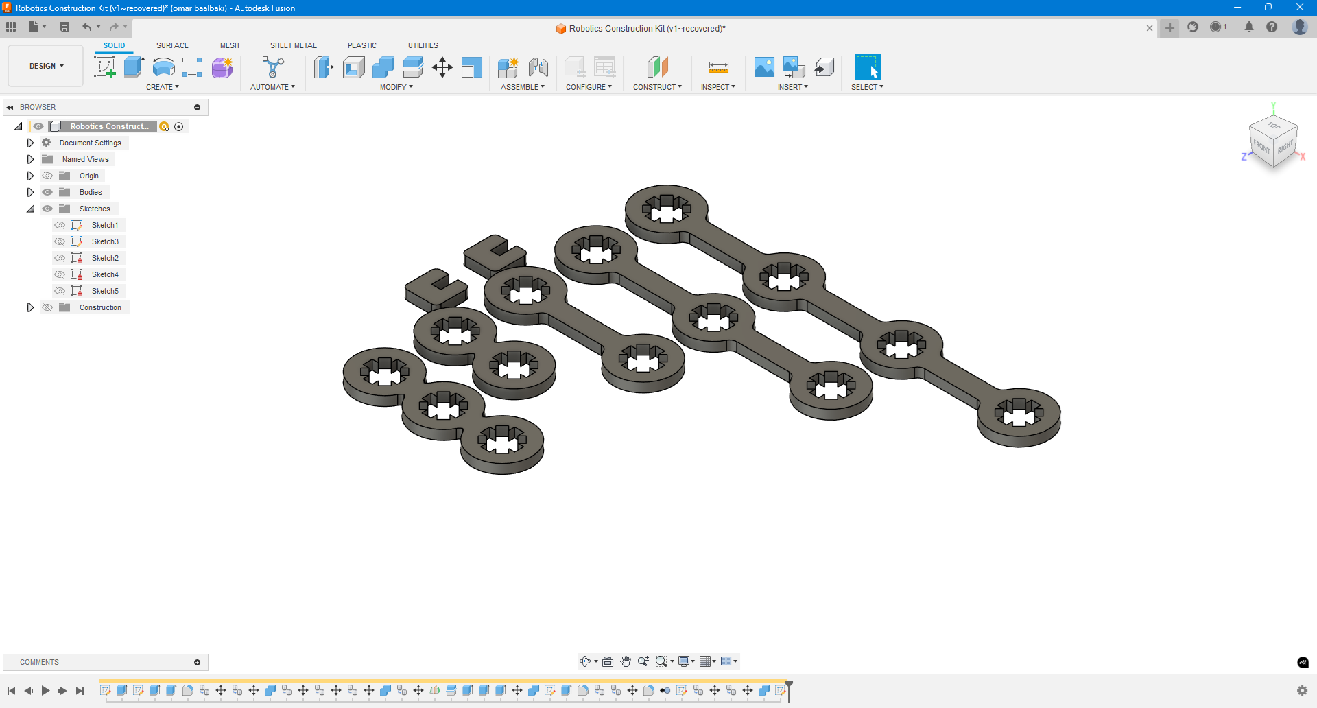
- After deciding on a more structured approach, I moved to Fusion 360 for design.
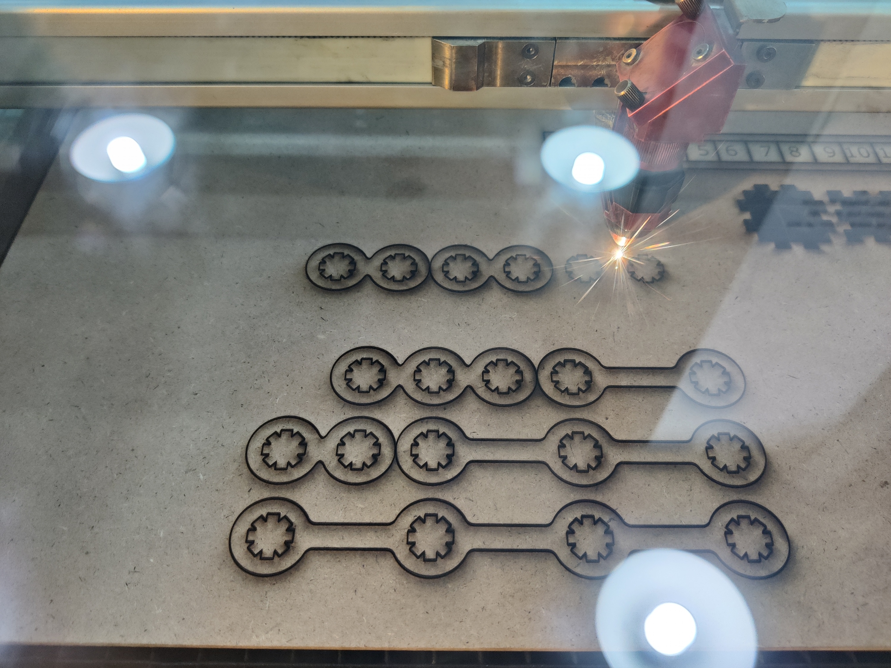
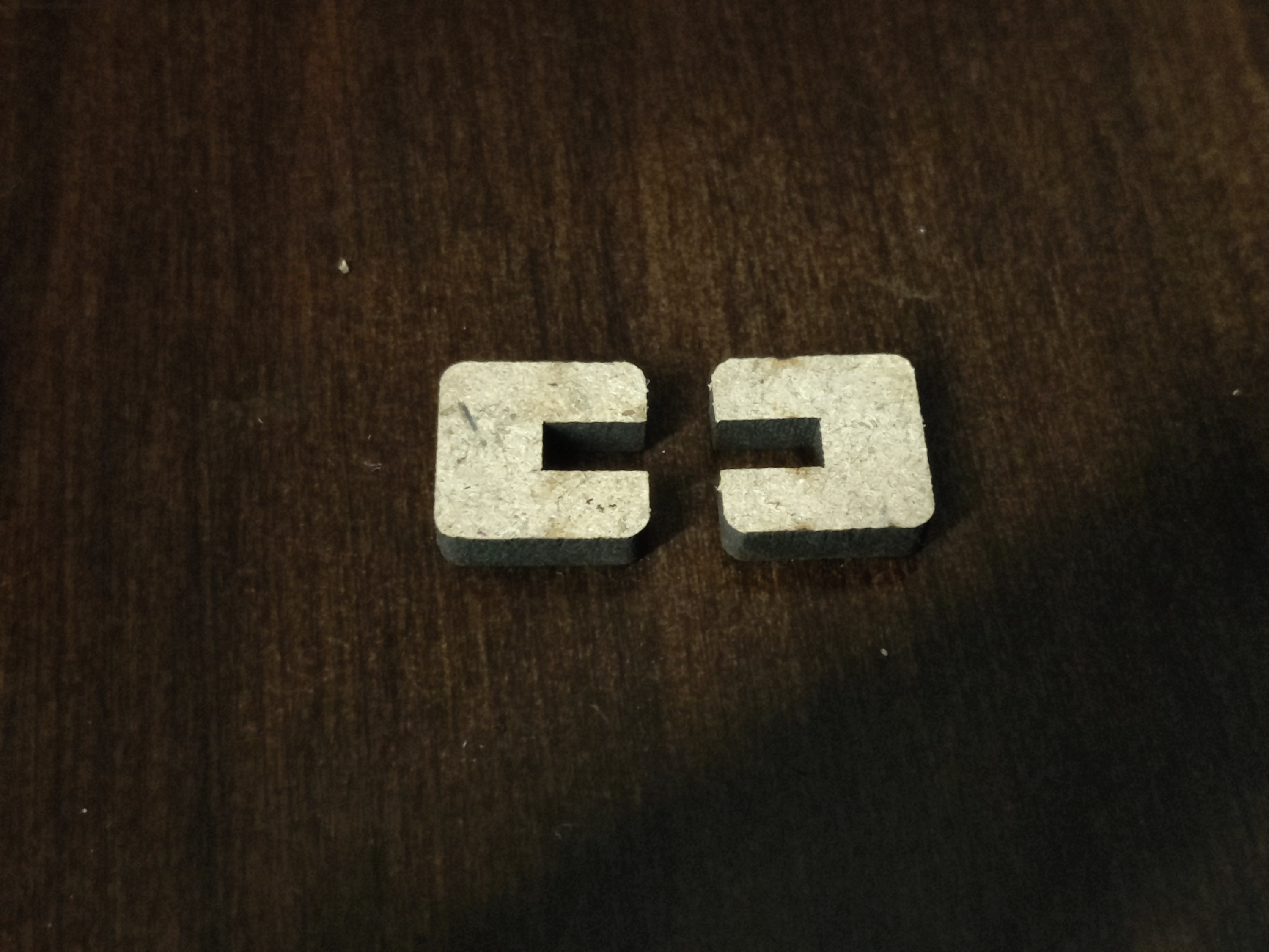
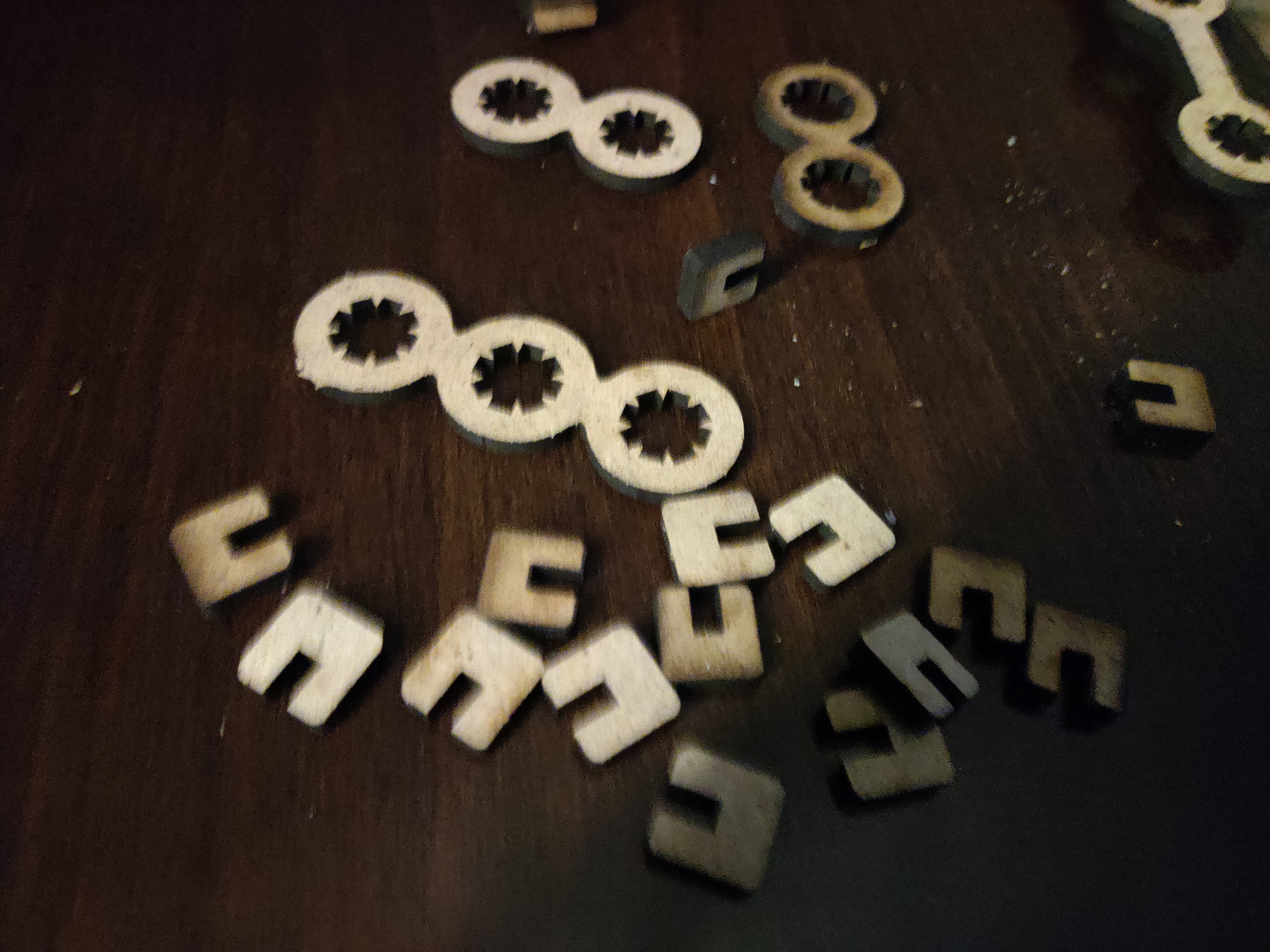
- Designed a modular system consisting of:✅ Links (rigid parts that connect the joints).✅ Joints (rotational or sliding elements that enable movement).
- Ensured the design had multiple connection points, allowing users to build different arm configurations.
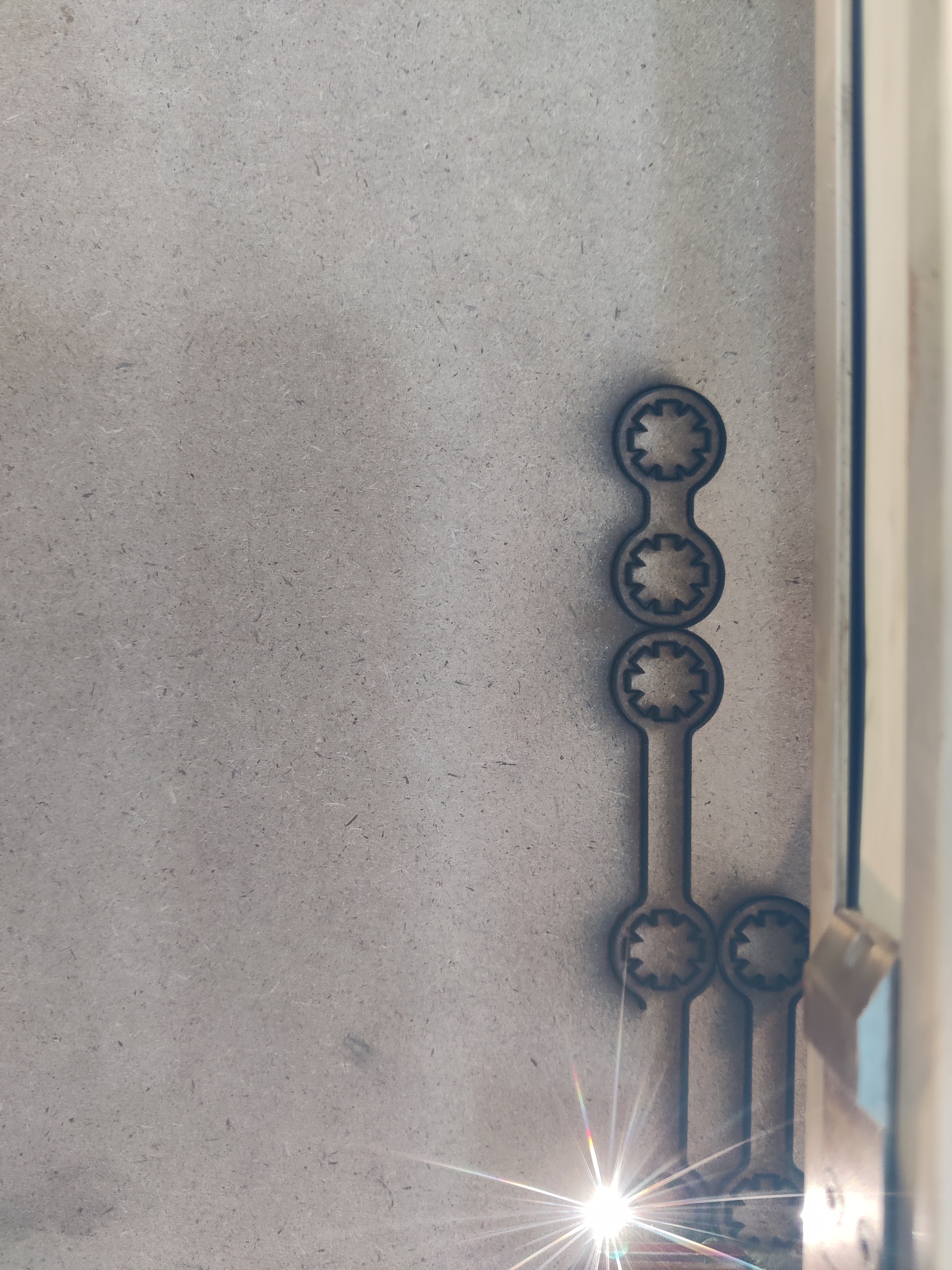
3. First Cutting Attempt and Issues Faced
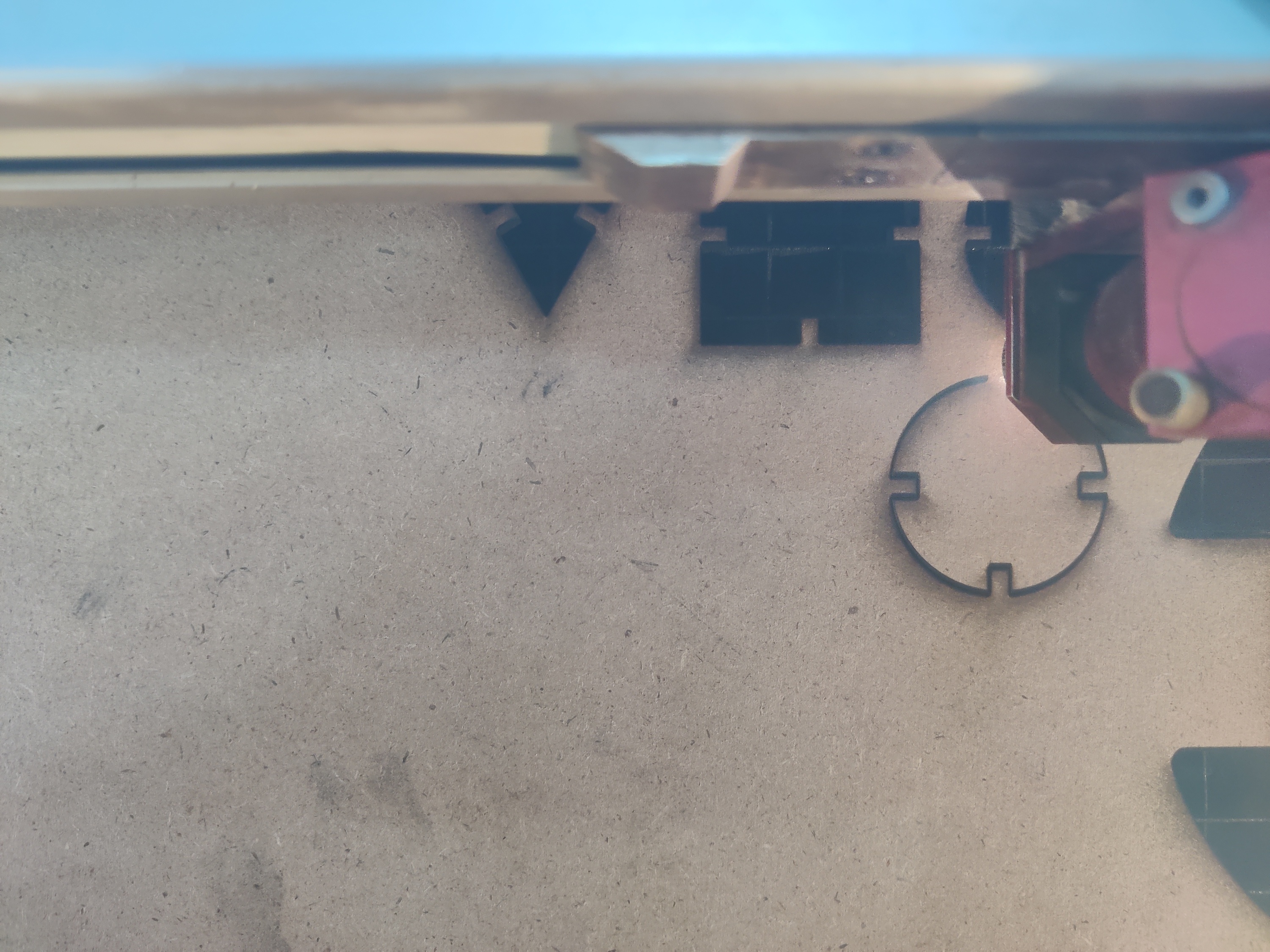
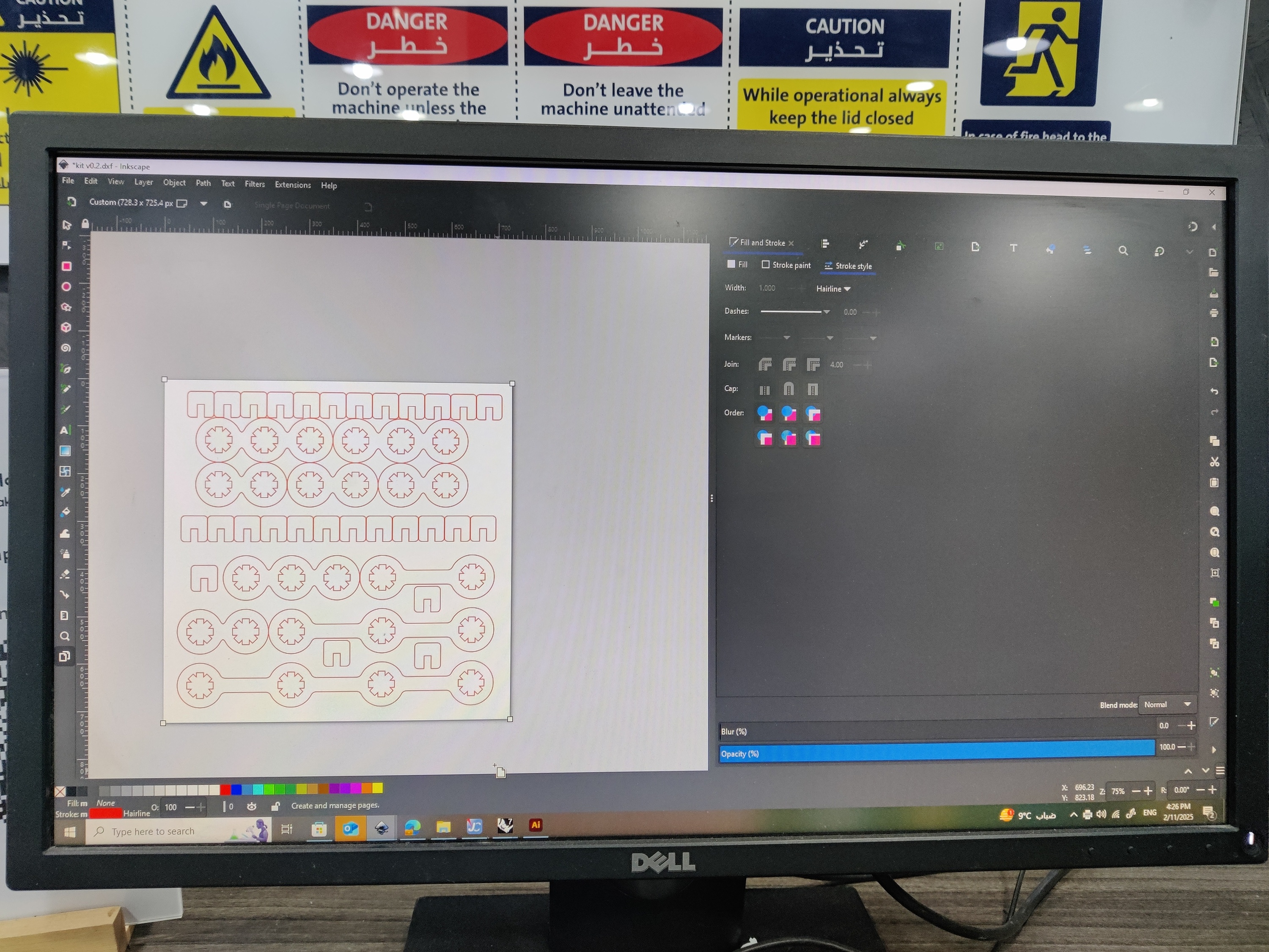
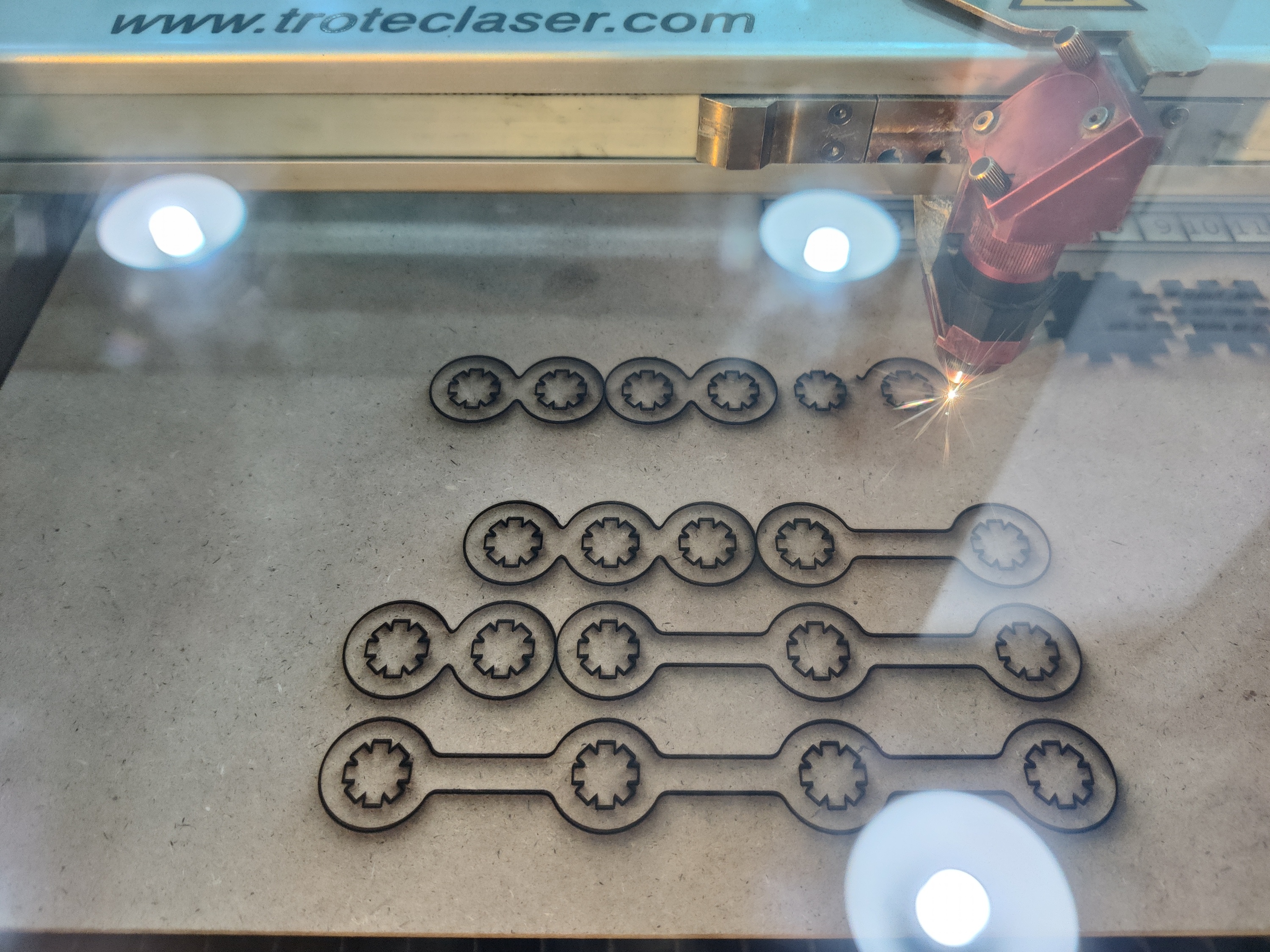
- Imported the design into Trotec JobControl for laser cutting.
- Used MDF (Medium-Density Fiberboard) for prototyping.
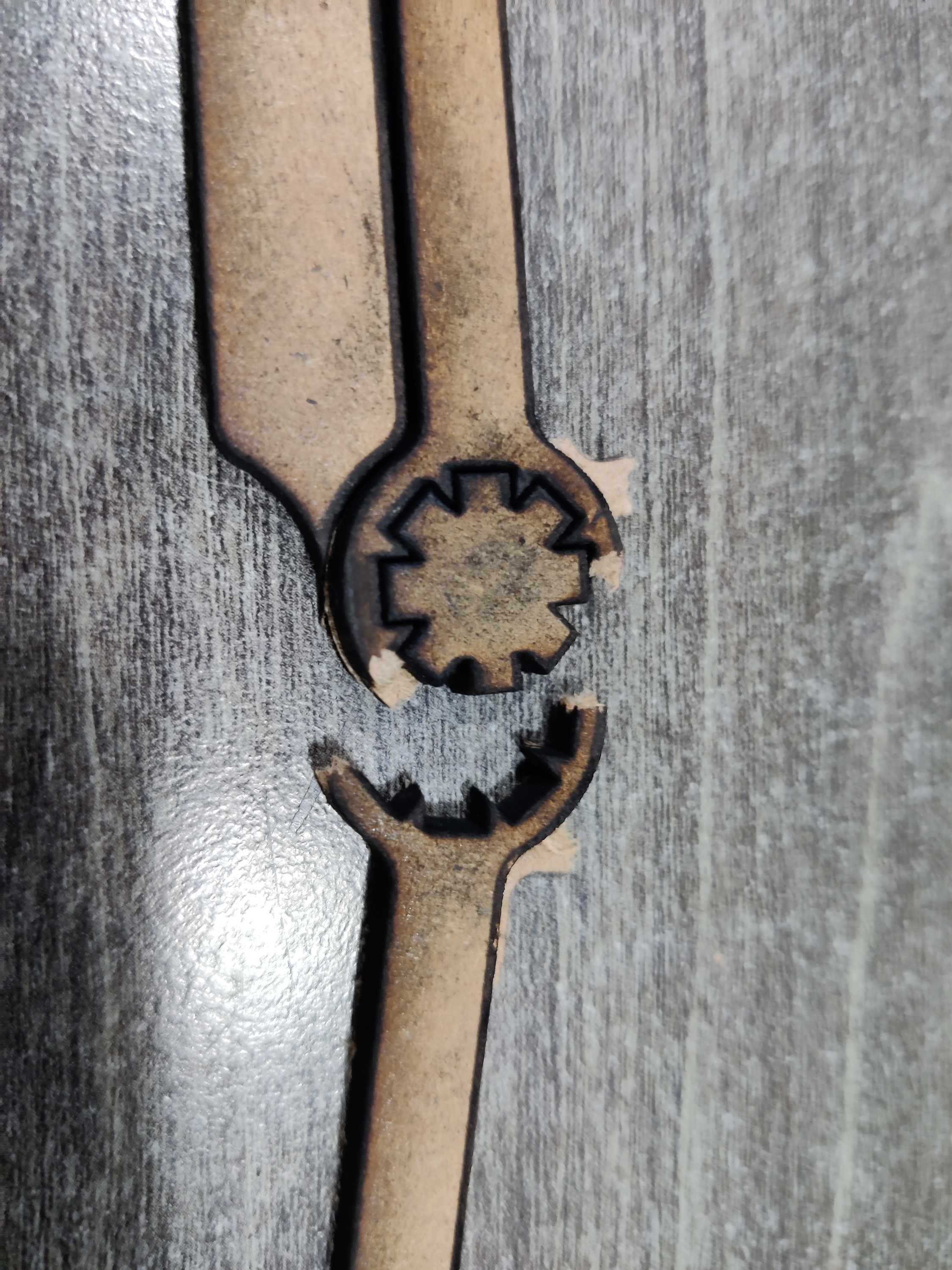
- Problem Encountered: The MDF was too thin, causing parts to break easily during assembly.
- Realized that the calibration process from the previous week was crucial in adjusting material settings to prevent over-burning or weak connections.
4. Refining the Design and Second Prototype
- Increased the thickness of the material to improve durability.
- Added reinforcement features to critical joint areas to prevent breaking.
- Cut the new version of the robotic arm kit with three links and three joints.
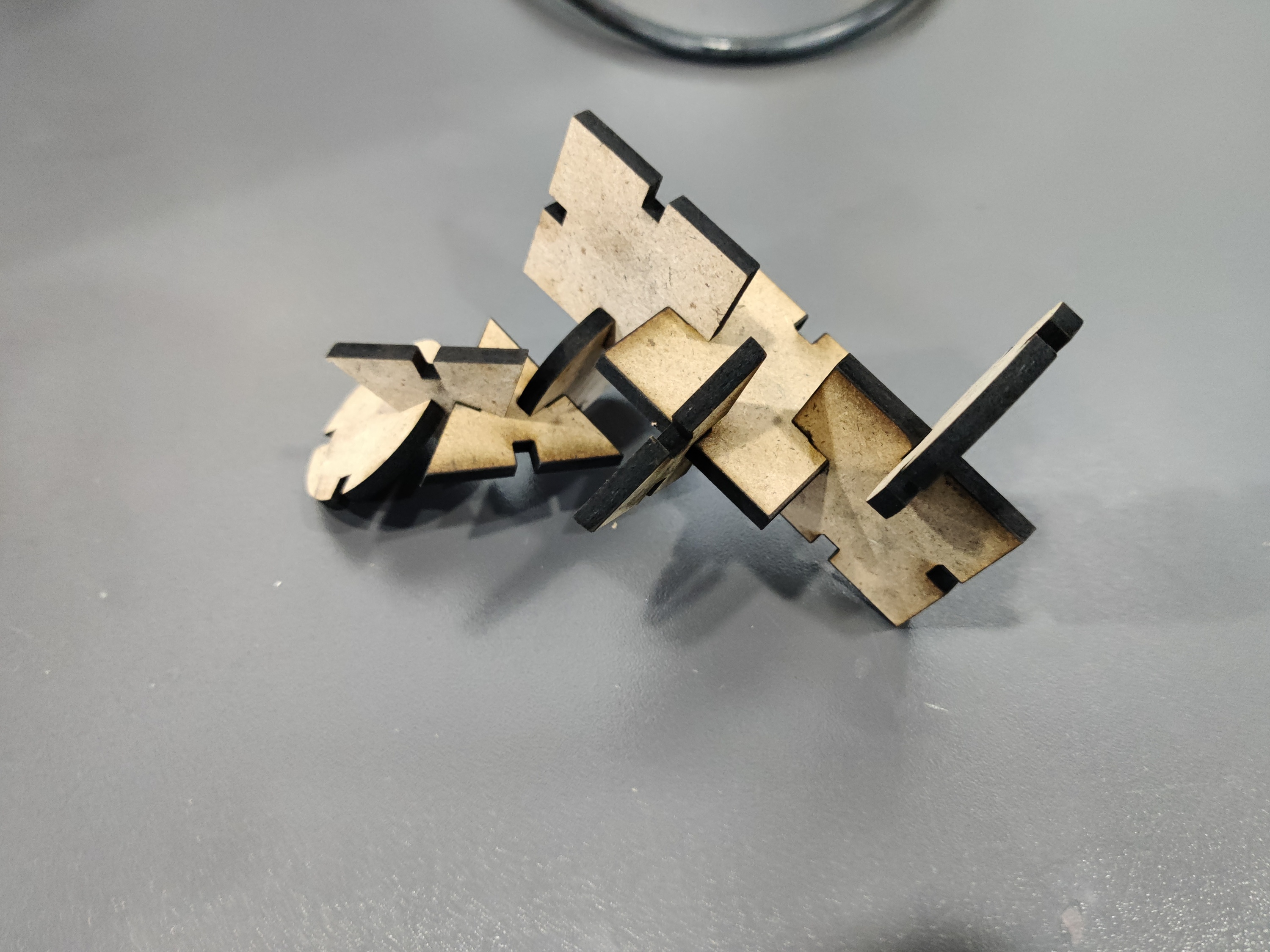
- Assembled the new model successfully without breaking.
5. Final Assembly and Testing
- Assembled the modular robotic arm to test joint flexibility and movement.
- Verified that the joints function smoothly, demonstrating real kinematic motion.
- Found that the construction kit effectively helps visualize robotic kinematics, making it easier to understand motion principles.
Learning Outcome
Through this project, I gained a deeper understanding of robotic kinematics by designing and building a laser-cut construction kit. I learned the importance of iterative design, where testing and refining the prototype led to significant improvements.
This project also reinforced the necessity of material selection and calibration in laser cutting to achieve durable and functional parts. Additionally, using Fusion 360 helped me develop skills in parametric design and precise modeling for fabrication.
Overall, this hands-on experience enhanced my ability to translate theoretical concepts into physical models, making complex robotic motion easier to visualize and understand.