CNC + Fusion
Hero Shot
Summary
After learning the PCB milling process, I used Fusion CAM to manufacture my PCB. I started by reading the mill tool datasheet to determine the correct feed rate and spindle speed. Next, I studied the copper thickness to ensure proper depth calculations. Using FSWizard, I verified my machining parameters before setting up my toolpaths in Fusion 360. After simulating the cutting process, I uploaded the G-code to the CNC machine, milled the PCB, soldered the components, and finally uploaded and tested the firmware.
Work Process Detail
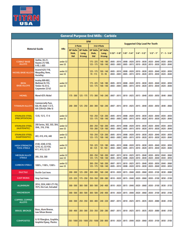
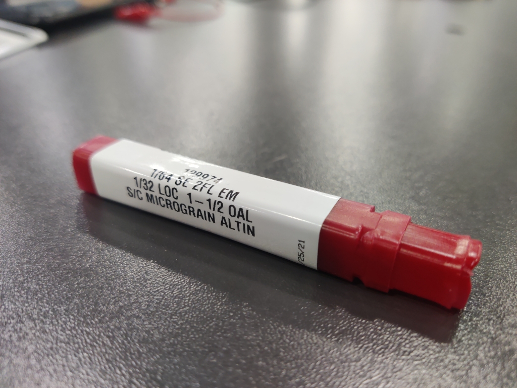
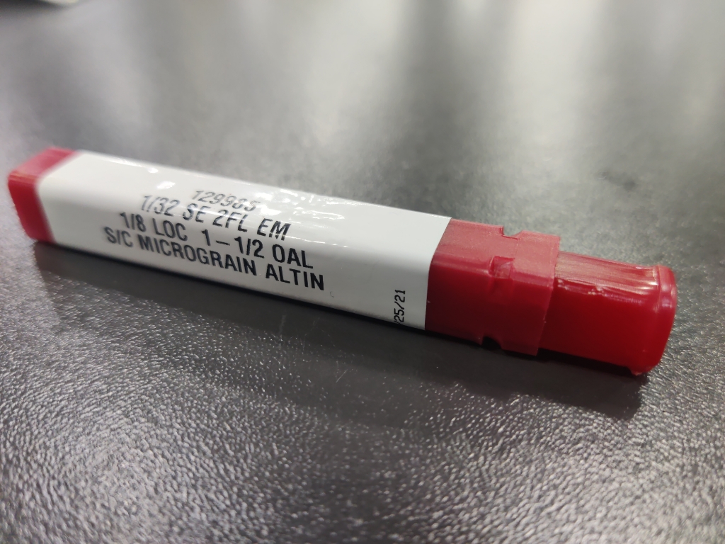
1. Calculating Feed Rate & Speed Using Mill Tool Datasheet
- I reviewed the mill tool datasheet to determine the appropriate cutting feed and spindle speed.
- Ensured that the parameters were suitable for PCB milling without damaging the copper layer.
📷 In this photo: The mill tool datasheet showing the recommended feed rate and spindle speed.
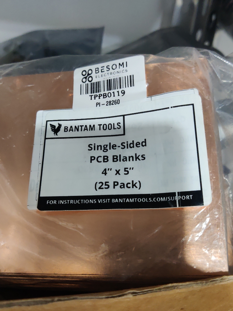
2. Understanding Copper Thickness for Proper Milling Depth
- Visited a copper manufacturer’s website to check the standard copper thickness for PCB fabrication.
- Verified the copper cladding thickness to adjust the milling depth settings accordingly.
📷 In this photo: A copper-clad board.
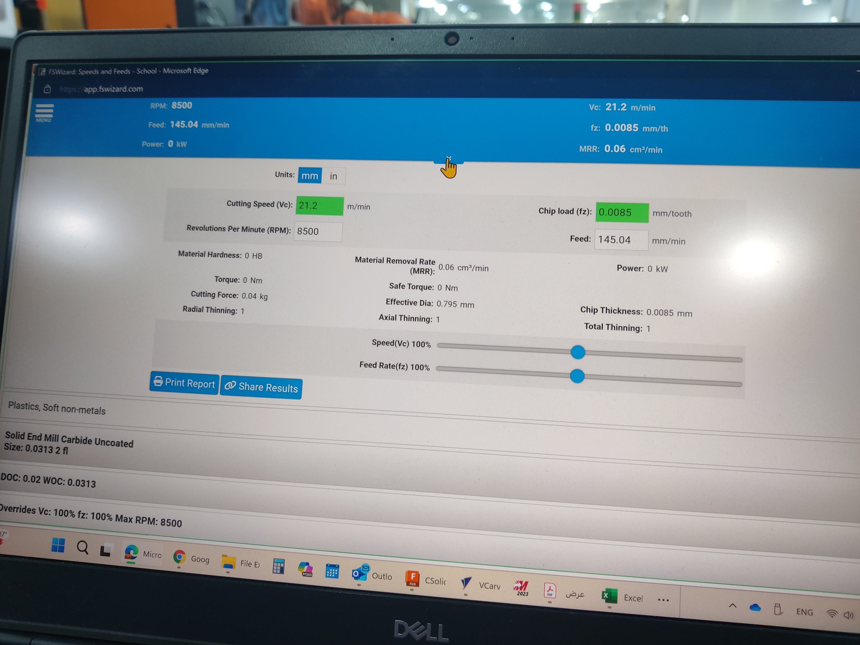
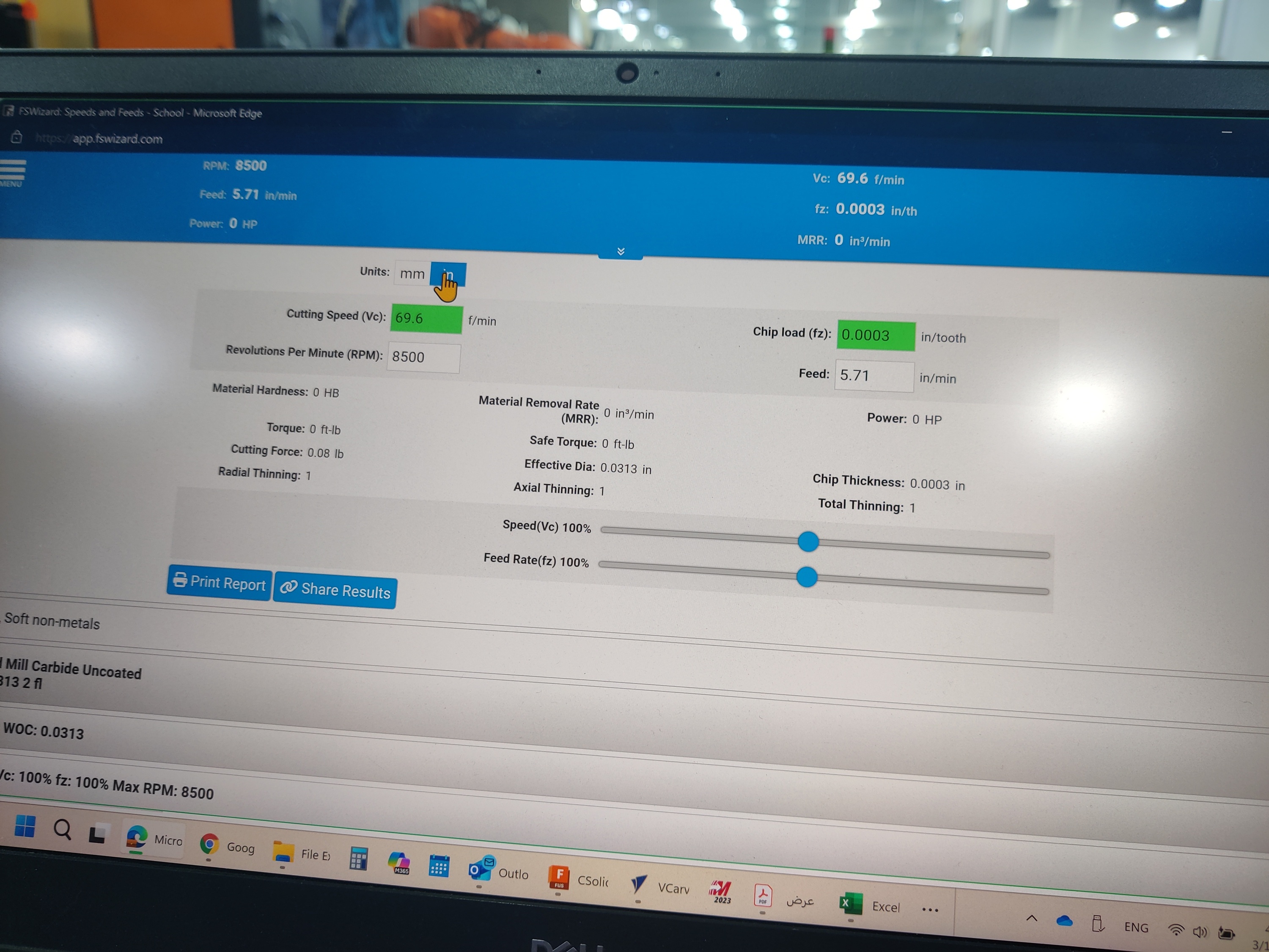
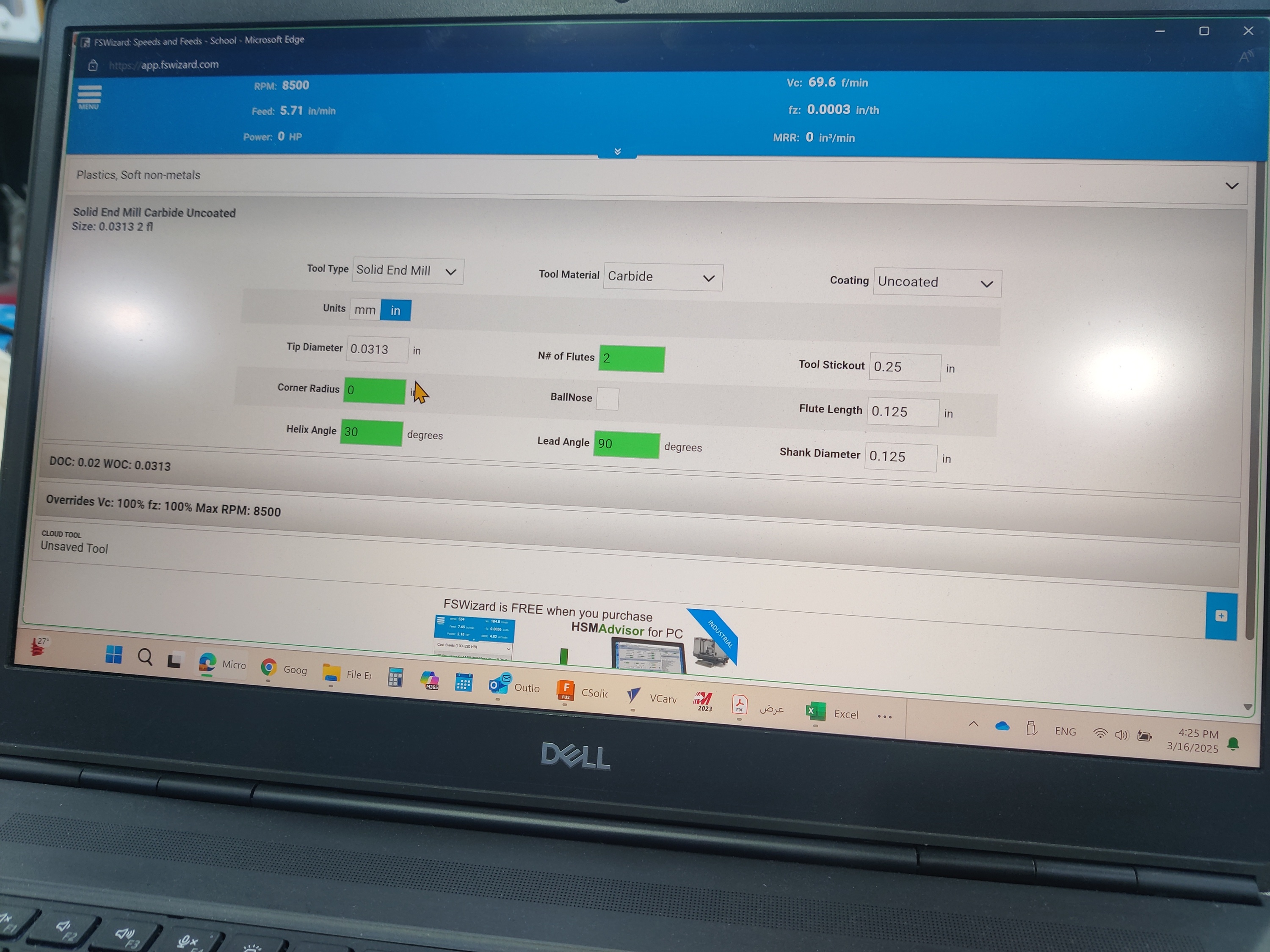
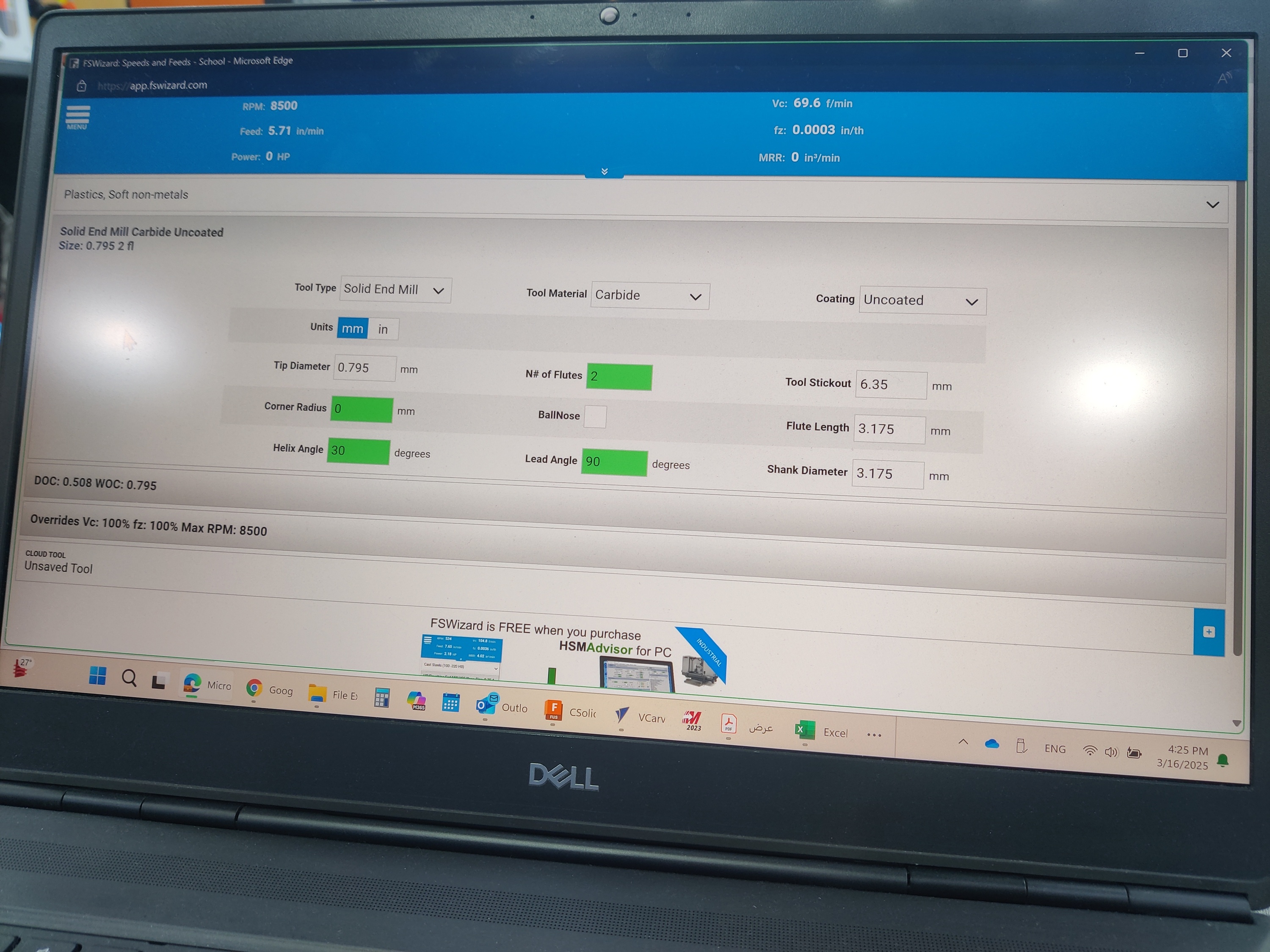
3. Using FSWizard to Verify Cutting Parameters
- Input the spindle speed, feed rate, and material properties into FSWizard for verification.
- Cross-checked the chip load and depth of cut to ensure the machine settings were optimized.
📷 In this photo: The FSWizard interface showing the calculated milling parameters.
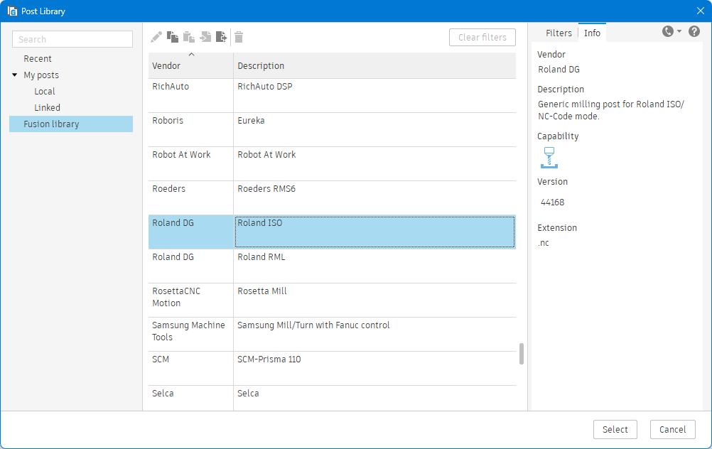
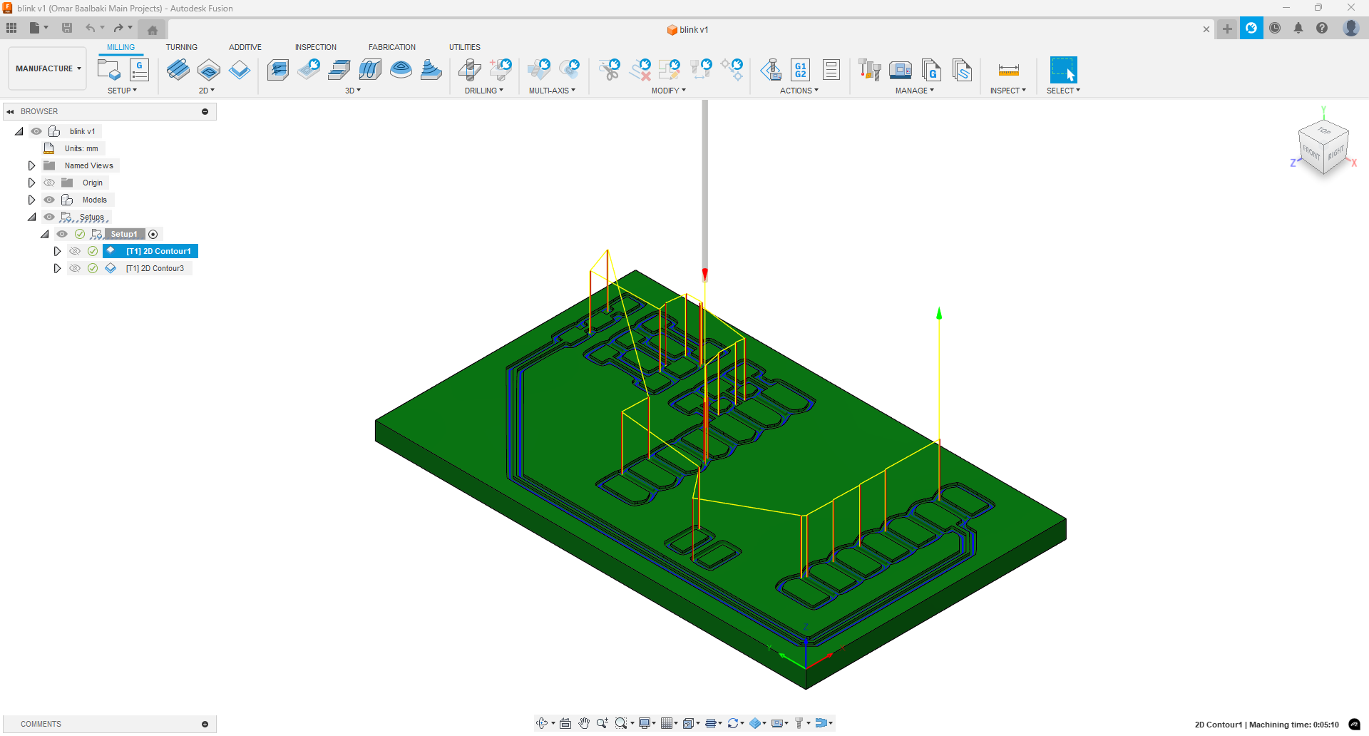
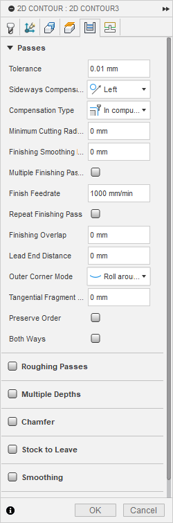
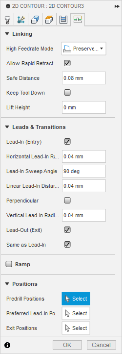
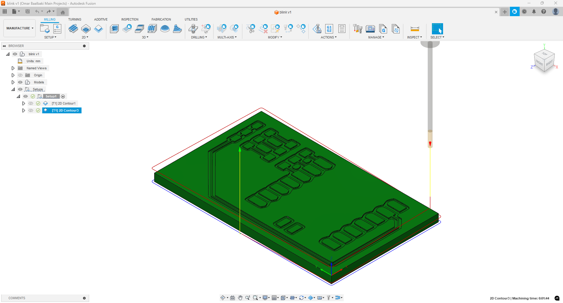
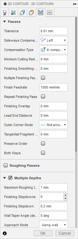
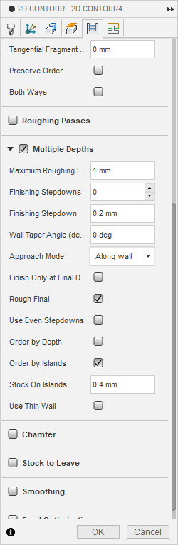
4. Setting Up the Machining Process in Fusion CAM
- Opened Fusion 360 and checked that the correct post-processing library was available.
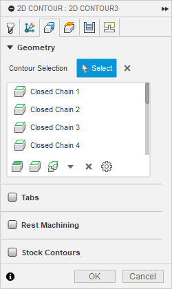
- Defined the toolpaths for cutting the PCB traces, holes, and board outline.
- Simulated the milling process to check for errors before generating the final G-code.
📷 In this photo: The Fusion 360 CAM setup with toolpath simulation running.

5. Uploading the G-Code to the CNC Machine & Milling the PCB
- Transferred the G-code to the CNC milling machine.
- Mounted the PCB blank securely and ran the milling process.
- Ensured that the cut depth and trace width matched the design specifications.
📷 In this photo: The CNC machine milling the PCB with the correct toolpaths.
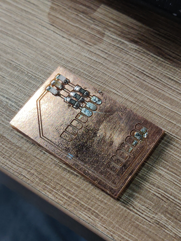
6. Soldering the Components & Testing the PCB
- Once milling was complete, I cleaned the PCB and checked for short circuits.
- Soldered the electronic components, ensuring proper alignment and connections.
📷 In this photo: The soldering process with the PCB partially assembled.
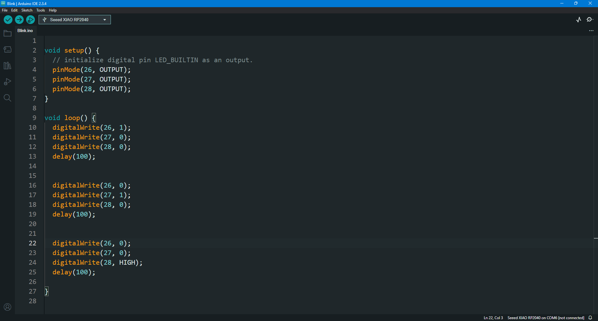
7. Uploading the Code & Testing the PCB
- Connected the PCB to a microcontroller, uploaded the firmware, and tested its functionality.
- Verified that the PCB worked as expected, checking for any electrical or software issues.
📷 In this photo: The PCB connected to a microcontroller for testing.
Learning Outcome
1️⃣ Understood how to calculate feed rate and speed using the mill tool datasheet.
2️⃣ Learned about copper thickness and how it affects milling depth.
3️⃣ Used FSWizard to verify cutting parameters for safe and efficient PCB milling.
4️⃣ Set up toolpaths in Fusion CAM, simulated the cutting process, and generated G-code.
5️⃣ Successfully milled the PCB, soldered components, and verified circuit functionality.
6️⃣ Uploaded firmware to test the PCB, ensuring that all electronic connections worked correctly.