* Demonstrate and compare the toolchains and development workflows for available embedded architectures * Document your work to the group work page and reflect on your individual page what you learned.
Project Management (part 2 of 2)
* Browse through the datasheet for your micro-controller. * Write a program for a micro-controller, and simulate its operation, to interact and communicate.
checklist
☑ Linked to the group assignment page. ☑ Browsed and documented some information from your micro-controller's datasheet. ☑ Programmed your simulated board to interact and communicate. ☑ Described the programming process(es) you used. ☑ Included your source code. ☑ Included ‘hero shot(s)’.
Browse through the datasheet for your microcontroller
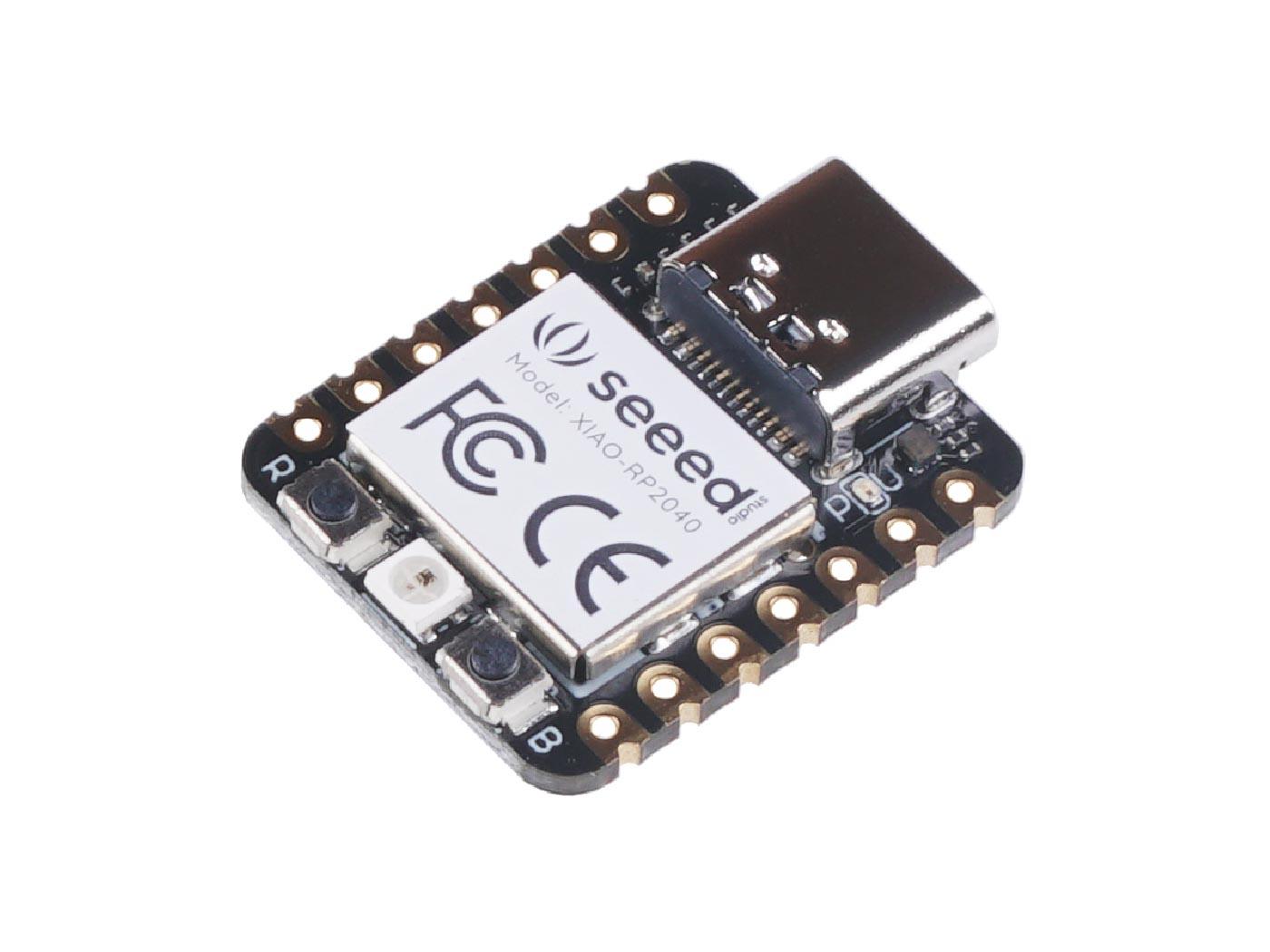
This week I am going to learn something new about embedded programming, which is a totally new topic to me, as I am not into this field before. After a brief explaination from my instructor - Mr. Steven Chew, and a discussion with my group buddy - Mr. Florimond Chu, I have decided to use Seeed XIAO RP2040 Micro-controller and Arduino Processing Language for this week assignment, and also for my final project application.
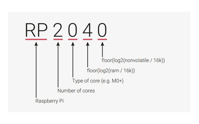
Before I dig myself deep into the micro-controller that I am going to apply into my project, there is something interesting that why the chip was named "RP2040". They are actually base on a post-fix numeral on RP2040 which represent the following as shown below and in the image:
RP2040 is a low-cost, high-performance microcontroller device with flexible digital interfaces. Key features: * Dual Cortex M0+ processor cores, up to 133MHz. * 264kB of embedded SRAM in 6 banks. * 30 multifunction GPIO. * 6 dedicated IO for SPI Flash (supporting XIP). * Dedicated hardware for commonly used peripherals. * Programmable IO for extended peripheral support. * 4 channel ADC channels (3 externals - GPIO26, GPIO27, GPIO28 and 1 internal - for measuring VSYS/3)with internal temperature sensor, 500ksps, 12-bit ADC resolutions (0-4095). * USB 1.1 Host/Device.
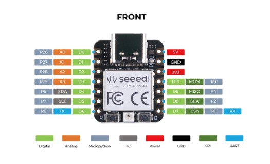
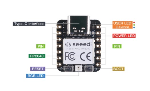
Below are the anatomy images of the SEEED XIAO RP2040 micro-controller with its components:
There are a total of 600+ pages of documents that I have referred to, and all these are so foreign to me. Thanks to Mr. Steven Chew, with both my instructors - Mr. Willie Tay and Mr. Bartholomew Ting to spend time explain to me to understand the basic in terms of the correspondence pin assignment of Xiao RP2040 for arduino IDE processing programming. In the meantime, I also referred to the Wiki as it has very good documentation for beginners (Home > XIAO > XIAO RP2040 > Getting Started with Seeed Studio XIAO RP2040).
Write a program for a micro-controller, and simulate its operation, to interact and communicate.
For this section, I will use WOKWI to write a simple program for RP2040 micro-controller that the LED is bilnking ON and OFF and simulate it. Since I have set myself to use SEEED XIAO RP2040 as my micro-controller and Arduino IDE as my processing programming for my final project, I will just put my head into this combination.
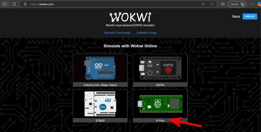
Setting Up in WOKWI simulator
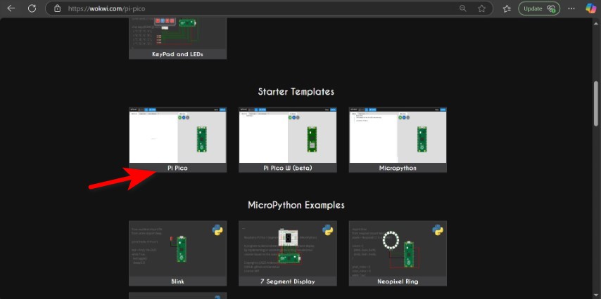
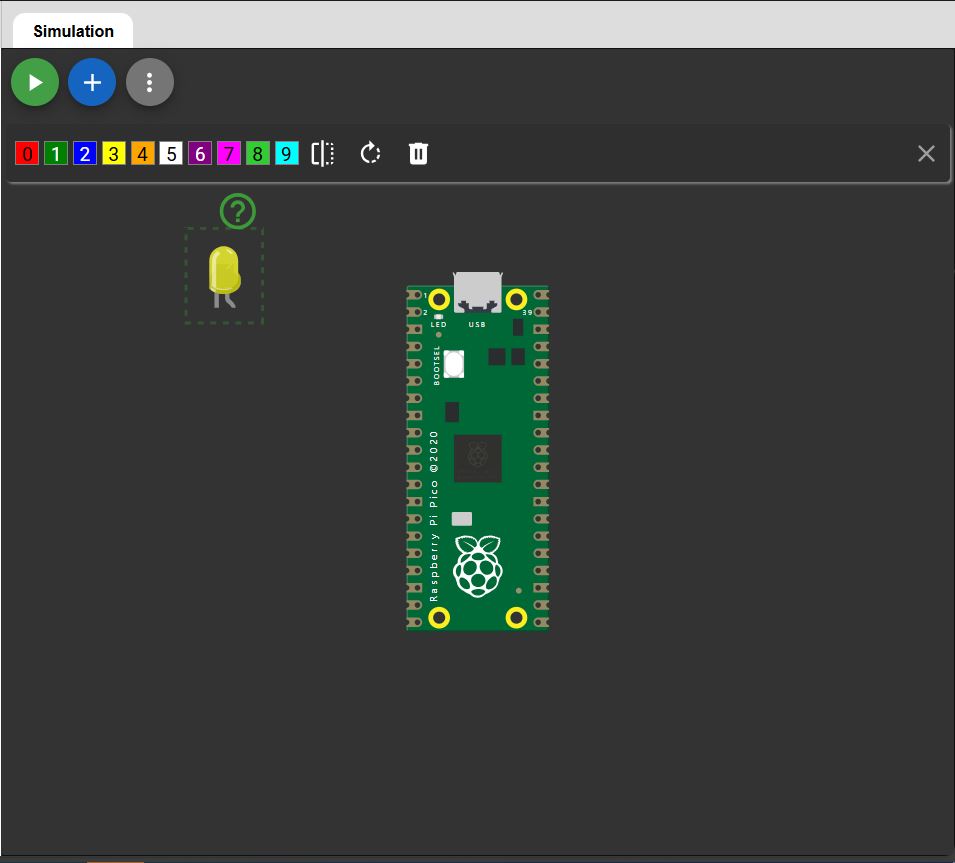
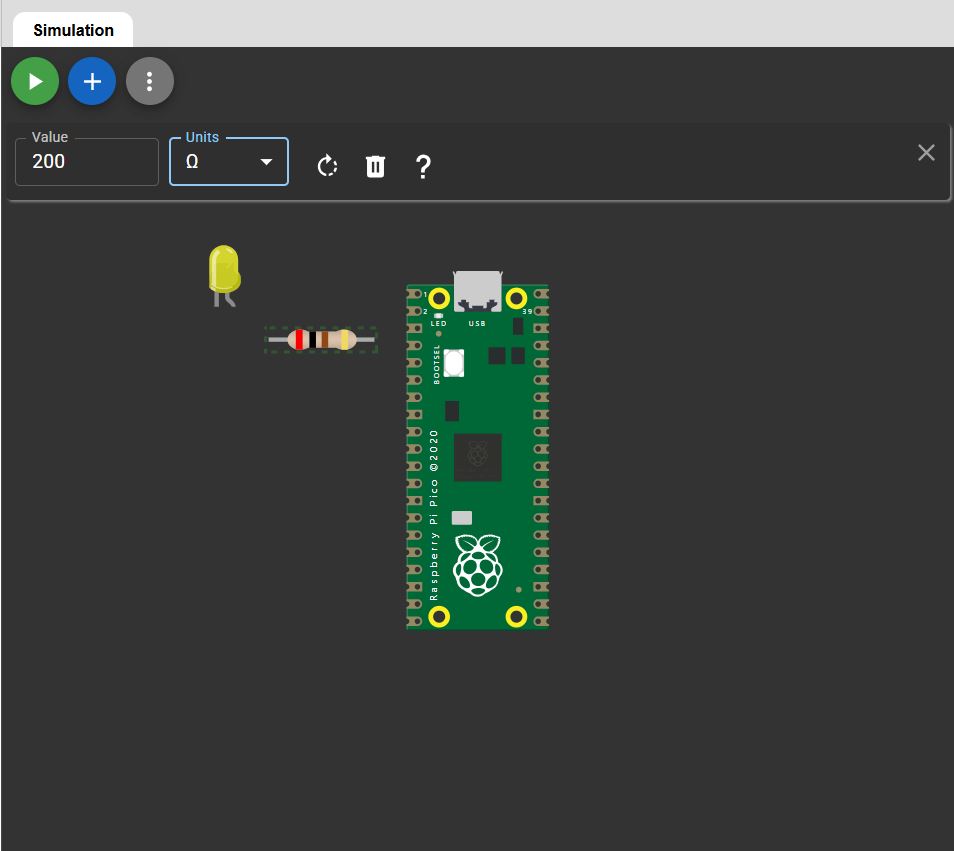
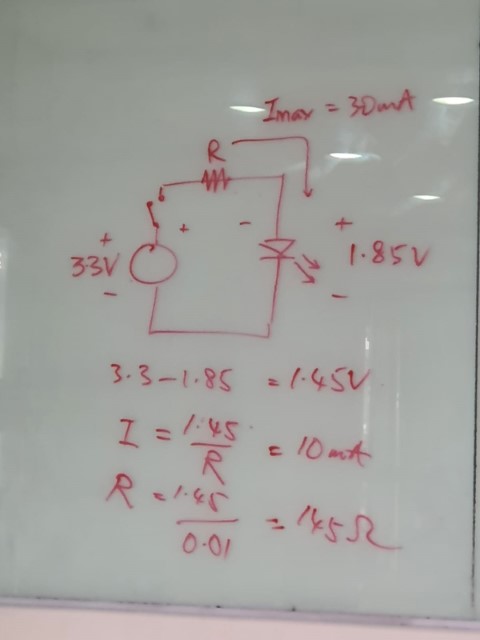
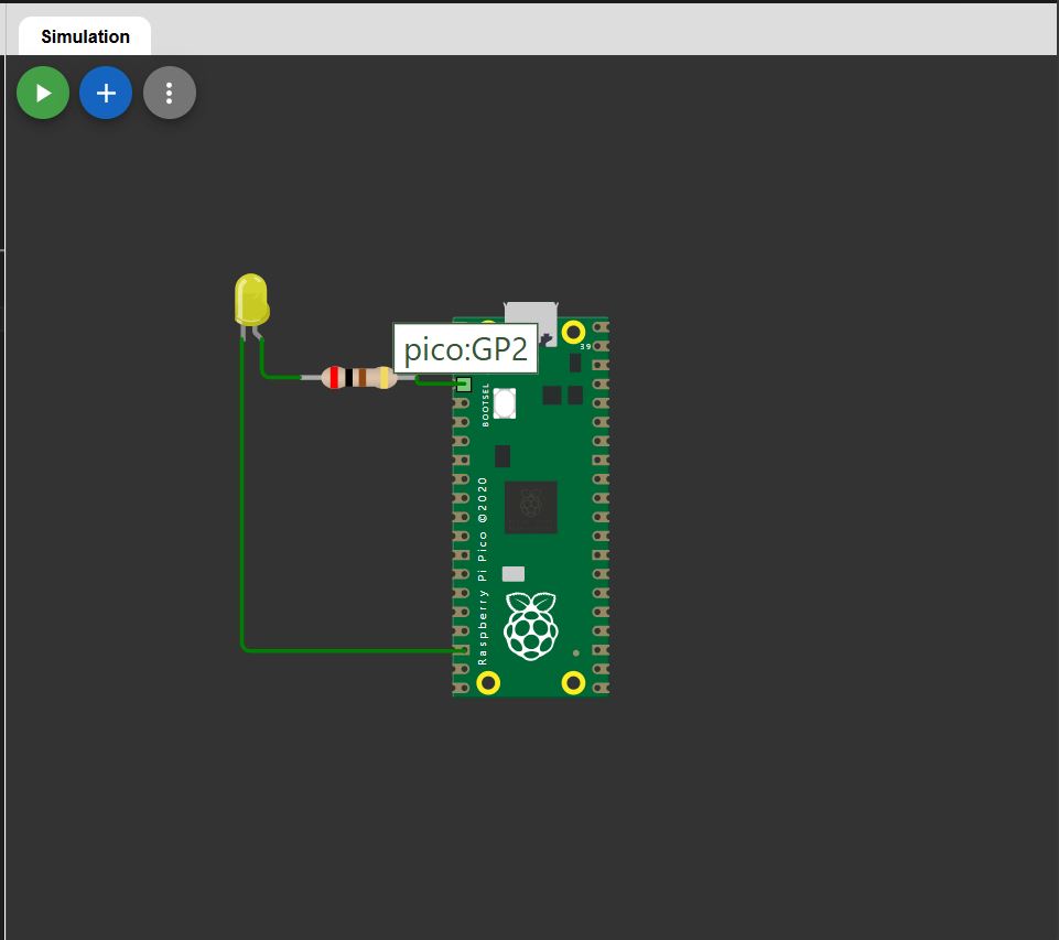
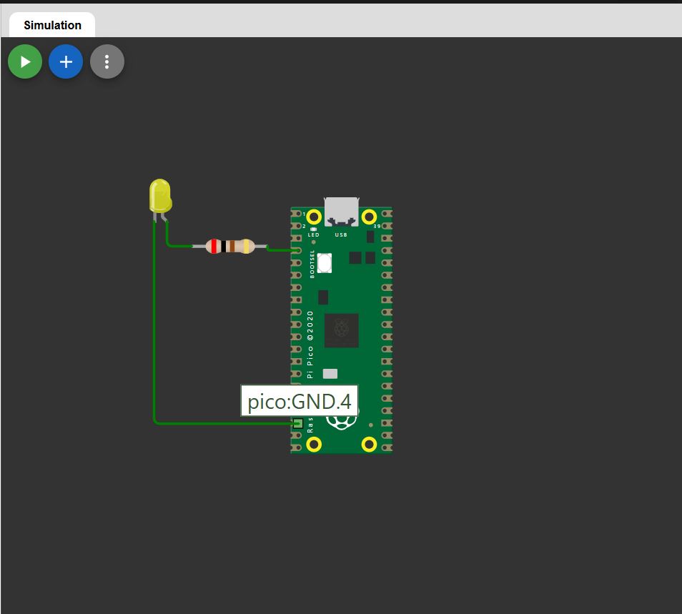
Go to the WOKWI website and select the Pi Pico. Select a starter template. For me, I will just choose the basic one. Next, click the “+” button to add an LED and a resistor to the simulator. In this case, I have set the LED color to yellow, and the resistor value to 200 ohms. Small Note to know: How I give a number for the resistor that I choose? Given Input Voltage, V(in) = 3.30V, Output Voltage, V(out) = 1.85V (refer to LED Voltage), Max Current = 30mA --> Nominal Current, I(norm) = 10mA, Knowing equation, V(total) = I(norm) x R, where R is the unknown Resistance figure that we need to know. After solving the equation, we know that the resistance cannot be lower than 145ohm. So, it is OK that 1 pick a 200ohm resistance for my simulation. Link the component up. The Positive polarity of the LED link with the 200ohm resistor before going into PICO:GP2, where the Negative polarity of the LED will direct link to PICO:GND.4
Write a Program
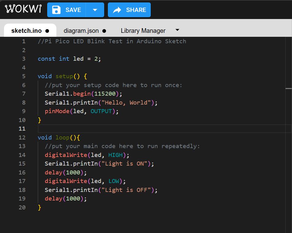
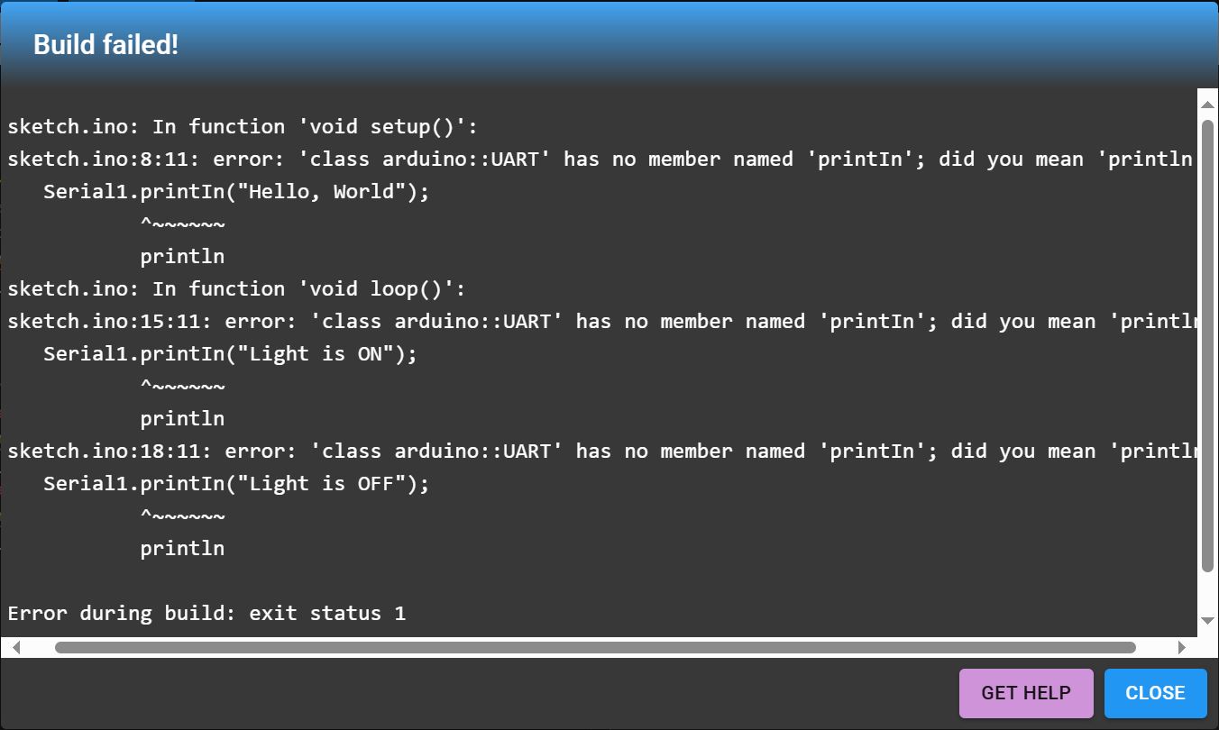
Once I have the components connected, I can begin coding. What the Code does: 1. Initializes Serial1 communication. 2. Prints "Hello, World" once. 3. Sets GPIO 2 as an output. 4. In the loop: o Turns the LED ON for 1.0 second. o Prints "Light is ON" to the serial monitor. o Turns the LED OFF for 1.0 second. o Prints "Light is OFF" to the serial monitor. o Repeats indefinitely.
Error occurs when trying to run the simulation. It turns out that the "printIn" was not an Uppercase letter "I" but was lowercase letter "L". Once I amended the mistakes, the program runs correctly:
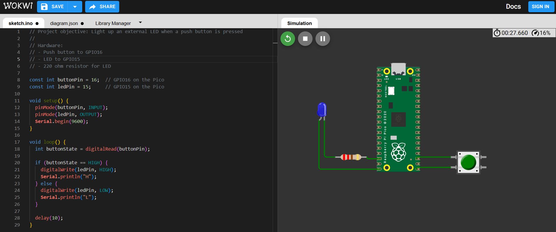
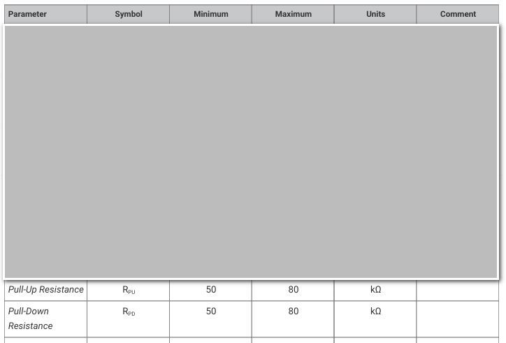
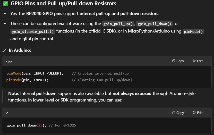
Stretch a bit further, my instructor, Mr. Steven Chew was asking me to add a pushbutton and write code to control the led using the pushbutton. I thought it was a good chance for me to learn a bit more on programming. Here is the code with the simulation diagram: One good thing about SEEED Xiao RP2040 is that they have Pull-up and Pull-down Resistors, refer to the chart below (reference from documentsPage 617, Table 625): This means that we don't need to have any external resistor for my pushbutton. Credit to ChatGPT: Do remember to on the sound so that you can link yourself with the simulation of the Blue LED is toggled on-and-off only when the push button was pressed.
As a conclusion, it has been a tough week for me to understand the terminologies of all the programming languages, not just the micro-controller itself. Fortunately, this is just a basic introduction on programming for me, and it gives me an overall idea how I should tackle for the upcoming weeks. I need to pick myself up as fast as I can so that I can convey all these knowledge to my final project.