Week 04 - Embedded Programming
Group Assignment:
• Demonstrate and compare the toolchains and development workflows for available embedded architectures
• Document your work to the group work page and reflect on your individual page what you learned
Demonstrating and Comparing Toolchains and Development Workflows for RP2040 and ESP32 Embedded Architectures
For this assignment, we will be exploring and comparing the development workflow for the RP2040 and ESP32. As we are both new to the world of microcontrollers, it was recommended that we try the RP2040 and ESP32, as these microcontrollers are commonly used for digital making projects and there are many resources available to learn about them. Using the following ChatGPT prompt, I generated a table summarizing the key functions between the RP2040 and ESP32 (below):
Prompt: Provide a short introduction to both RP2040 and ESP32, including:
• Key specifications (e.g., cores, clock speed, GPIOs, memory)
• Common use cases for each (e.g., RP2040 for educational projects, ESP32 for IoT applications)
| FEATURE | RP2040 | ESP32 |
|---|---|---|
| Processor | Dual-core ARM Cortex-M0+ (133 MHz) | Dual-core ARM Cortex-M3 (up to 240 MHz) |
| Clock Speed | 133 MHz | Up to 240 MHz |
| GPIO Pins | 26 digital I/O pins (some with additional features like PWM, ADC, I2C, SPI) | Up to 34 I/O pins |
| Memory | 264 KB SRAM, 2 MB flash | 520 KB SRAM, external flash (up to 16 MB) |
| Wireless Communication | None (requires external module for Wi-Fi/Bluetooth) | Built-in Wi-Fi and Bluetooth |
| Power Consumption | Low power usage (ideal for battery-powered projects) | Moderate to high power usage, but optimized for low-power modes |
| Common Use Cases | • Education and prototyping • Simple sensor projects • Learning embedded systems |
• IoT and smart home applications • Wearables and portable devices • Networking and cloud-connected applications |
| Strengths | • Affordable and simple for beginners • Great for educational projects and microcontroller learning |
• Robust networking capabilities (Wi-Fi, Bluetooth) • High processing power, ideal for complex applications |
Development Toolchains
As our group is very new to microcontrollers, we asked ChatGPT to explain what a toolchain is.
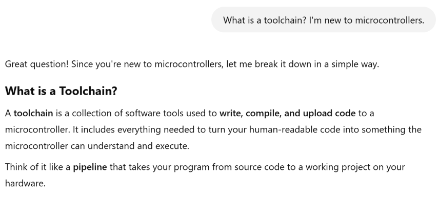
We then asked it to outline the toolchain used for both the RP2040 and the ESP32.
Prompt: Please outline the toolchain used for programming the RP2040/ESP32
RP2040 Toolchain:
• Language: MicroPython (for beginners) or C/C++ (for performance and advanced control).
• IDE/Editor: Thonny, VS Code, or Arduino IDE.
Toolchain:
• For MicroPython: MicroPython firmware, REPL.
• For C/C++: Raspberry Pi Pico SDK, CMake, GCC toolchain, Make.
• Flashing: USB drag-and-drop for simple projects, picotool for advanced workflows.
• Debugging: GDB, OpenOCD, or SWD debuggers for deeper debugging.
ESP32 Toolchain:
• Development Environments:
ESP-IDF (Official SDK for Advanced Users)
Arduino IDE (Beginner-Friendly)
PlatformIO (Flexible, VS Code-based)
MicroPython (For Python Developers)
• Compilation & Build
xtensa-esp32-elf-gcc (GCC Toolchain) CMake + Ninja for ESP-IDF builds.
• Flashing Tools
esptool.py, idf.py flash, Arduino Upload.
• Debugging
Serial Monitor, GDB + OpenOCD for JTAG Debugging.
• Additional Libraries
ESP-WIFI-MESH, ESP-NOW, LVGL, Home Automation Frameworks.
We can’t say we understood everything in the above-mentioned section about Toolchains, but we think we have enough to proceed to the next part.
Development Workflows
For the development workflows, we will explore:
• Seeed Studio XIAO RP2040 with MicroPython
• Seeed Studio XIAO ESP32C3 with Arduino
Seeed Studio XIAO RP2040 with MicroPython
For this exploration, we referred to the section “Seeed Studio XIAO RP2040 with MicroPython” in the Seeed Studio wiki.
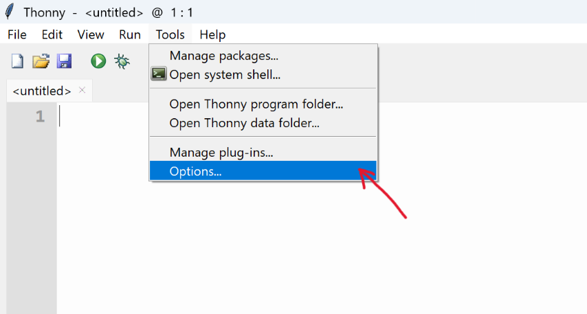
PART 1: Download and Install the Thonny editor
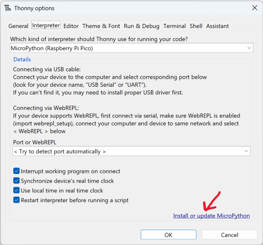
I downloaded the installer for the Thonny editor from https://thonny.org/, installed it, and then opened the app. Next, select "Tools > Options" to open the settings.
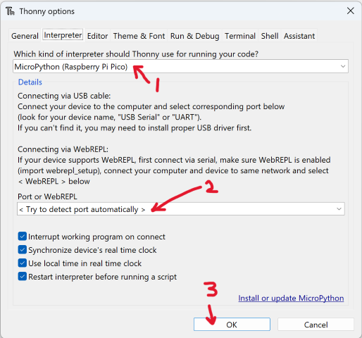
Choose the "Interpreter" interface and select the device as "MicroPython(Raspberry Pi Pico)" and the port as "Try to detect port automatically"
PART 2: Connect Seeed Studio XIAO RP2040 to the PC (Test Light)
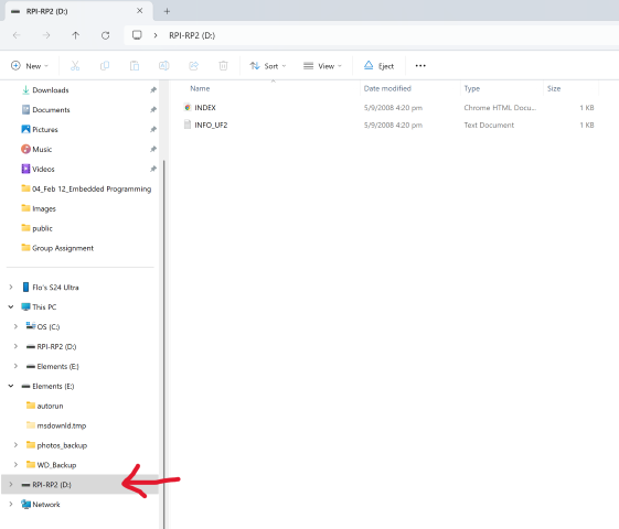
Press and hold the "BOOT" button (small button on bottom R) and then connect the Seeed Studio XIAO RP2040 to the PC using the Type-C cable. If successful, the PC recognizes the XIAO RP2040 and "RPI-RP2" appears.
Back in Thonny, select Install or update MicroPython.
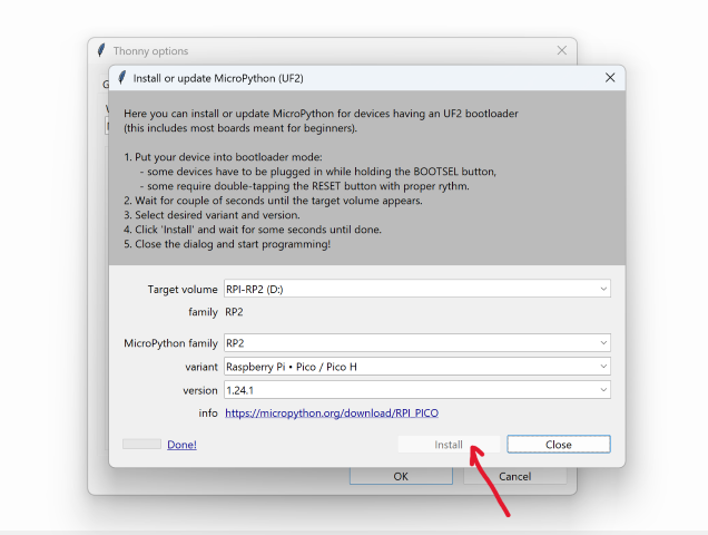
This will trigger an automatic search for the device and display it as the Target Volume. For the Micropython version, we left it as default. Click on the Install button and close this page when the installation is done.
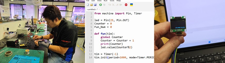
Next, we will need code to enable the XIAO RP2040 to do anything. We can either write the code ourselves or copy over the code from a reference. In this case, we copied over the code provided in the wiki to Thonny.
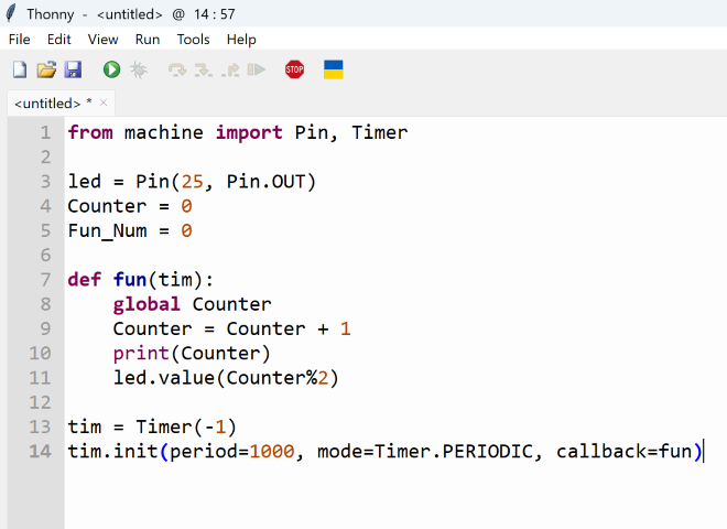
We upload the code to the XIAO RP2040 with the result of a alternating blue/green light shown in the following video:
PART 3: RGB LED Light Cycle on the Seeed Studio XIAO RP2040
We learnt that the XIAO RP2040 has an RGB LED already built into it and for this next part, we will:
1. Add a 3rd party library to the XIAO RP2040 to control the RGB LED
2. Run a code to cycle the LED colors
Add a 3rd party library to the XIAO RP2040 to control the RGB LED
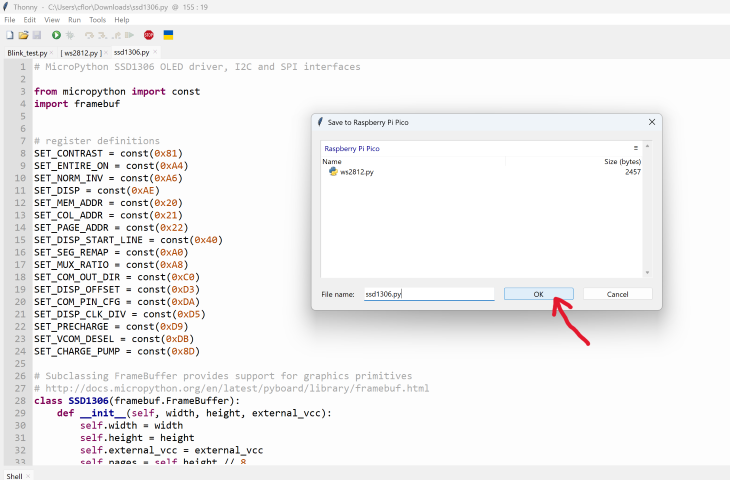
First, we downloaded the ws2812.py library and opened it with Thonny.
We then saved the library into the XIAO RP2040. (“File > Save as”, then save into "Raspberry Pi Pico"). The save file must be named “ws2812.py” in order to work.
Run a code to cycle the LED colors
We used a code provided in the wiki that we used to cycle the LED colors:
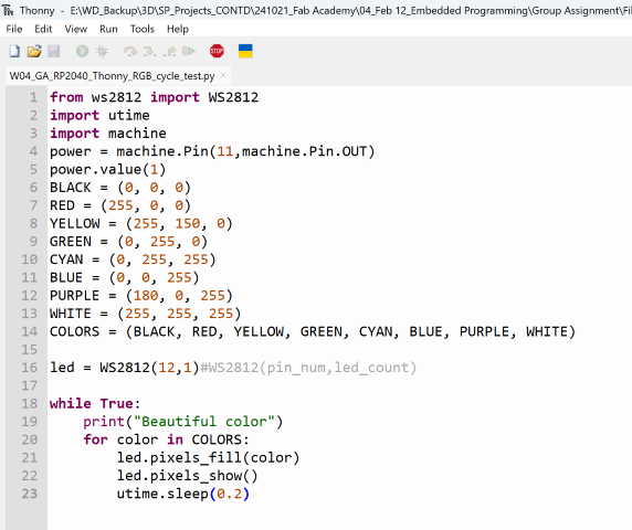
Below is a video showing the result of our test.
PART 4: Connect with Seeed Studio XIAO RP2040 with Display through IIC
For this part, we did not have the exact OLED component (The Grove - OLED Display 0.96" SSD1315) so we replaced it with a similar one we found in our lab.
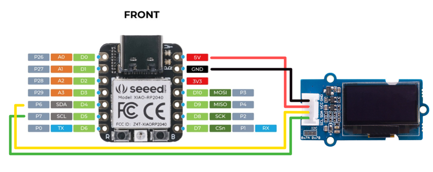
Hardware Setup
We soldered the pins onto the XIAO RP2040 and then wired it up according to this diagram.
Like the steps above, we downloaded a library to control the OLED.
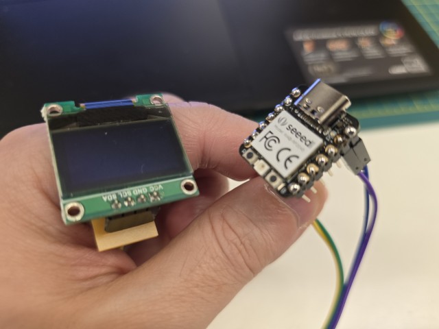
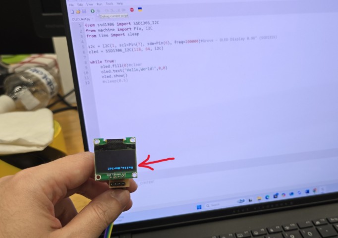
Once the library has been saved into the XIAO RP2040, we run the following code:
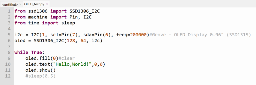
Success! We were excited to get it work and took the photo of the OLED upside down.
And this concludes our exploration of the XIAO RP2040 with Thonny. Next up, we explore the XIAO ESP32C3 with Arduino.
Seeed Studio XIAO ESP32C3 with Arduino
For this exploration, we referred to “Getting Started with Seeed Studio XIAO ESP32C3” in the Seeed Studio wiki.
PART 1: Software setup
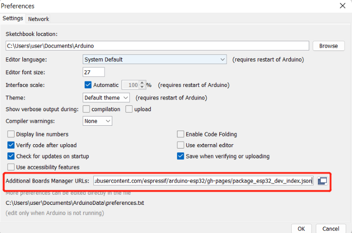
First, we must download and install Arduino IDE. Since we have already done this previously, we move on to adding the ESP32 board package to Arduino IDE. Navigate to File > Preferences, and fill "Additional Boards Manager URLs" with the url here: https://raw.githubusercontent.com/espressif/arduino-esp32/gh-pages/package_esp32_index.json
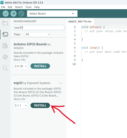
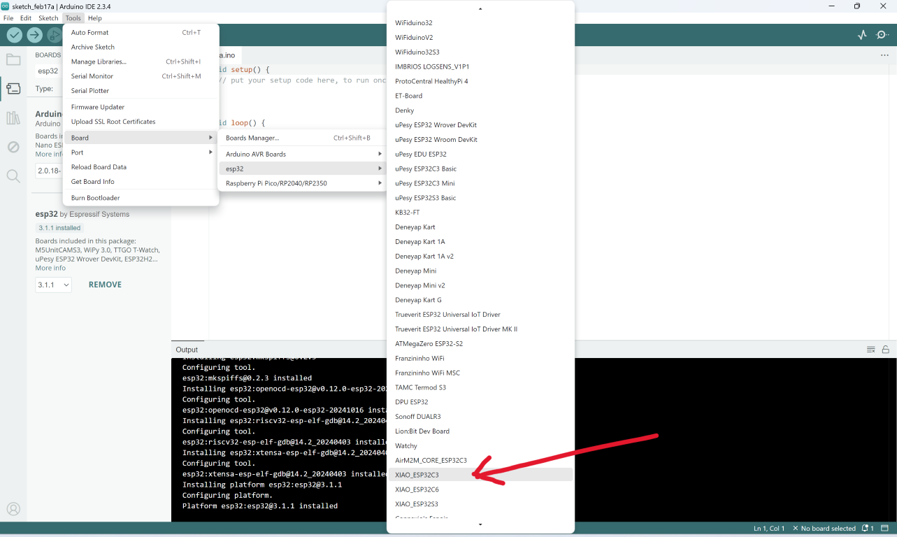
Navigate to Tools > Board > Boards Manager..., type the keyword "esp32" in the search box, select the latest version of esp32, and install it.
Next, we select the ESP32 board as shown below:
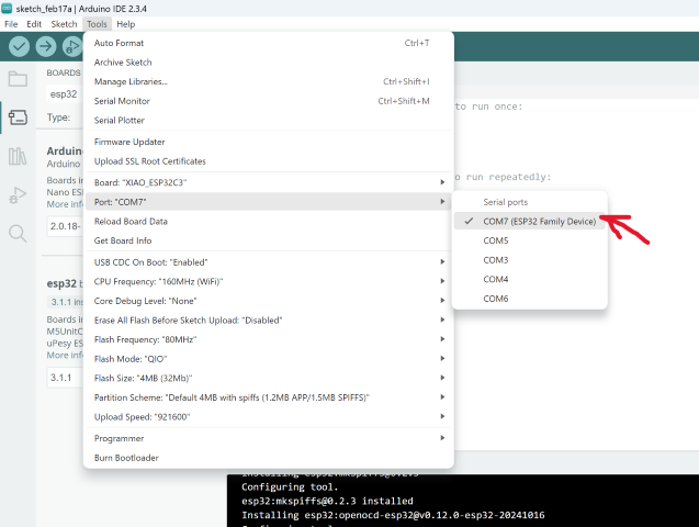
We then select the serial port name of the connected XIAO ESP32C3 (Tools > Port). In our case, it was PORT 7 on our PC.
PART 2: Hardware setup
For the Hardware Setup, we followed this diagram and soldered the components together.
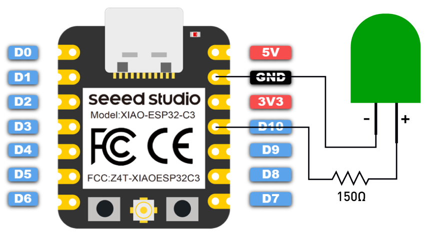
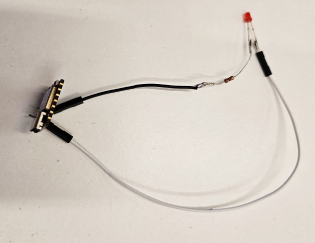
The only difference was that we used a 100 Ohm resistor instead of a 150 Ohm resistor.
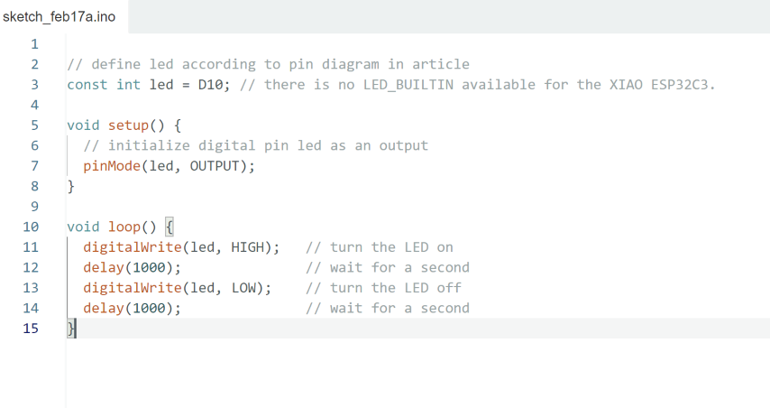
PART 3: Blink the LED
Before we can blink the LED, we need to have the code to run it. For this, we used the code provided by the wiki tutorial. The result can be seen in the video below.
Conclusion
Our experience of working with both Microcontrollers regardless of programming language felt similar to each other for the simple things we tried to do with them. Both involve downloading a code editor and using libraries to drive certain components. We think that the differences between the RP2040 and the ESP32 will become more distinct as we attempt to do more complex things in the future, such as getting the microcontrollers to control multiple components with different functions at the same time.
Files