Week 11 - Networking and Communications
Group Assignment:
• Send a message between two projects
• Document your work to the group work page and reflect on your individual page what you learned
Overview
For this week’s Group Assignment, we send a message between our XIAO RP2040 boards using I2C (Inter-Integrated Circuit).
We used ChatGPT to help us understand I2C better, and used the following prompt:
Prompt:
What is i2c?
ChatGPT’s reply:
What is I2C?
I2C stands for:
Inter-Integrated Circuit – a communication protocol that allows multiple devices (sensors, displays, other microcontrollers) to talk to each other over just two wires.
The Two Wires
SDA – Serial Data Line
SCL – Serial Clock Line
All devices share these two lines: One device acts as the master (controls the clock and initiates communication) Others act as slaves (wait to be told what to do)
Setup
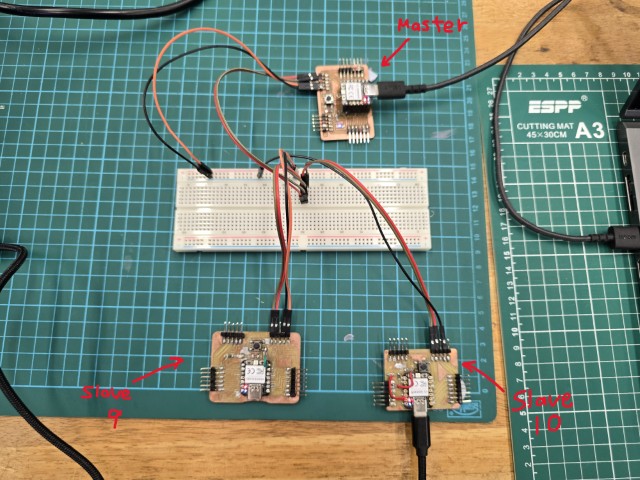
For our setup, we connected 3 XIAO RP2040 boards together as shown above.
In this setup we have:
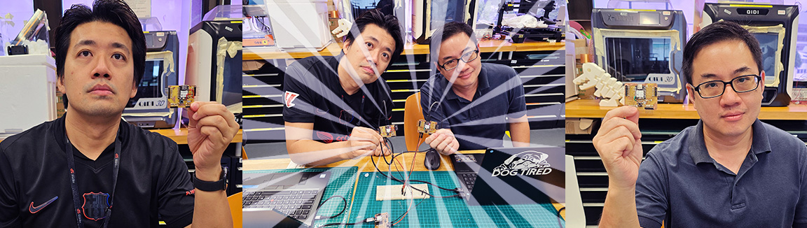
1. Master board - This is the board that we use to send instructions to the other two boards. We got this board from our instructor Steven.
2. Slave 9 – This is one of the slave boards that will receive the instructions. We named it 9 as that is the address that we assigned to it. This is Florimond’s board that was made during week 8 for Electronics Production.
3. Slave 10 - This is the other slave board that will receive the instructions. We named it 10 as that is the address that we assigned to it. This is Haw Ren’s board that was made during week 8 for Electronics Production.
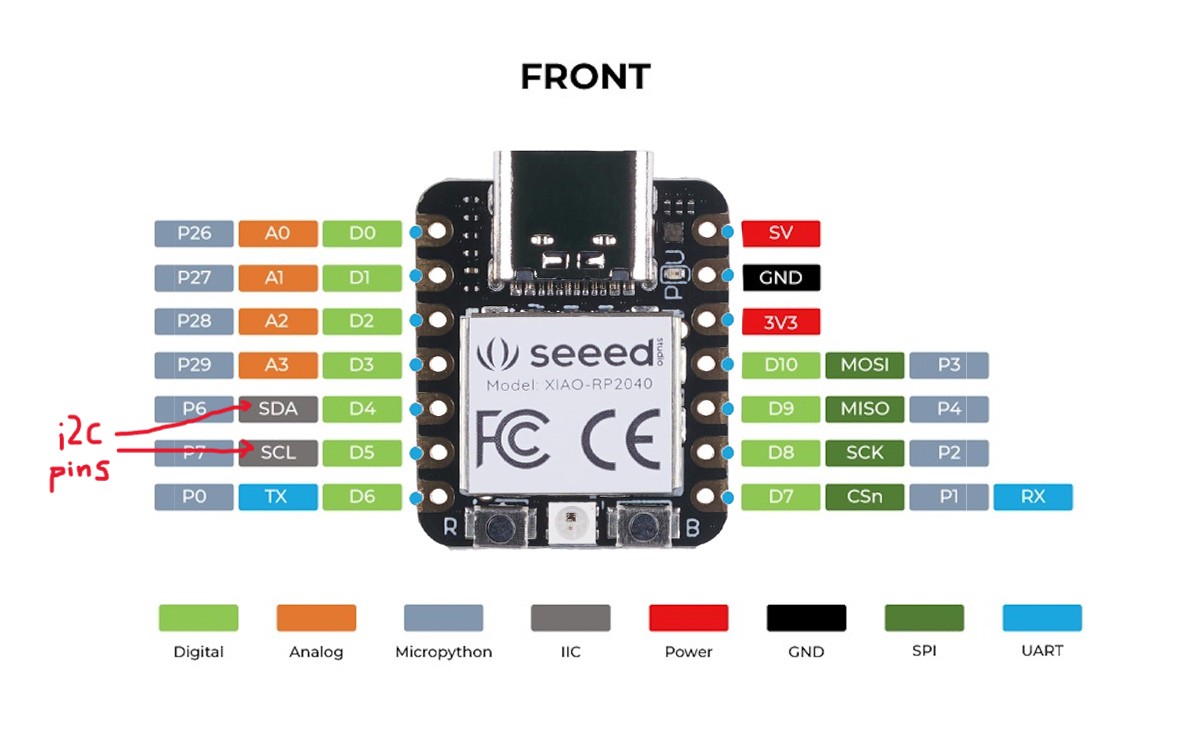
For the pins, we used the SDA and SCL pins that are dedicated to I2C.
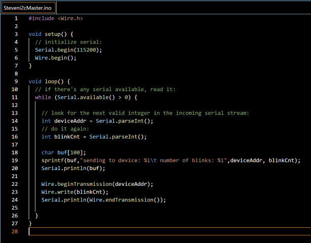
Program
We also need programs to run our I2C test. For this, we referred to the following I2C master-slave programs that our Fab Lab Alumni, Zi Hon wrote for Arduino UNO boards and adapted it for our XIAO RP2040 boards. Here are the screen captures of the code:
Master Program
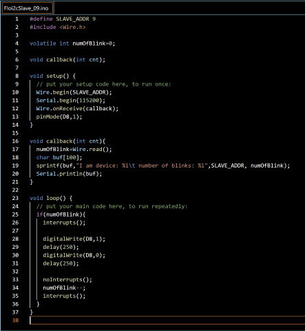
Slave 9 Program
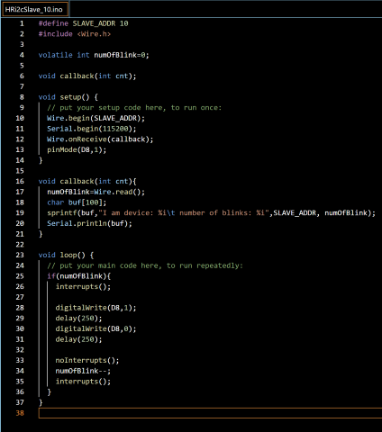
Slave 10 Program
A detailed line-by-line explanation of the code (from ChatGPT) is available here.
Expected Behaviour
If our programs work properly, we expect to see the following result:
1. We send an instruction from the master (via serial), say we type in 9 5 in the serial monitor for this example.
2. The master sends the value 5 to slave address 9 over I2C.
3. The slave receives the number 5, stores it in numOfBlink, and blinks the LED 5 times.
4. Then, the LED stops blinking — because numOfBlink becomes 0. Knowing this, we proceed to the next step – uploading the programs to our boards and then observing the results.
Sending the message
We send the following instructions out from our master board by typing the commands in the Serial Monitor :
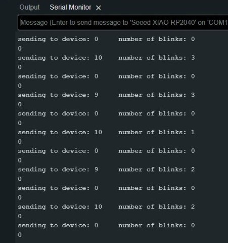
The following was observed on the slave serial monitors:
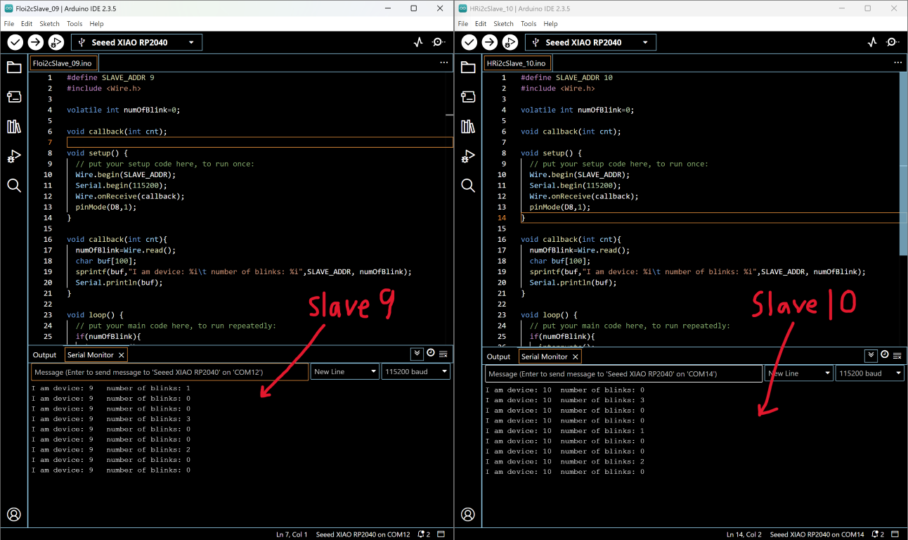
These results were observed on the slave boards:
| Master (What we typed in) | Slave 9 (What we observed) | Slave 10 (What we observed) |
|---|---|---|
| 9 1 | Blinks once | No reaction |
| 10 3 | No reaction | Blinks thrice |
| 9 3 | Blinks thrice | No reaction |
| 10 1 | No reaction | Blinks once |
| 9 2 | Blinks twice | No reaction |
| 10 2 | No reaction | Blinks twice |
Below is a video recording of our test.
From our tests, we can conclude that the observed behaviour is the same as our expected result. Hence, we can conclude that our message was successfully sent and received using I2C.
This concludes our Group Assignment for this week.