Week 9: Input Devices: RFID RC522
Group Assignment
We probed the analog levels and digital signals and made detailed documentation is available on the Group Assignment Page.
Reflection on individual work is documented below.
Individual Assignment
Basics of electronics consists of three parts Input Device - Processor - Output Device
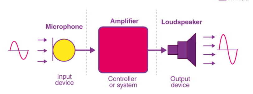
Different Types of Input Devices
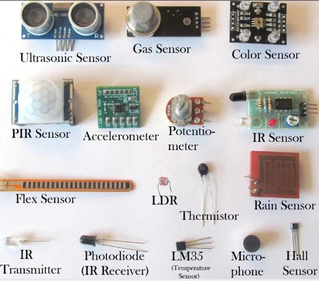
Measuring and Adding a Sensor
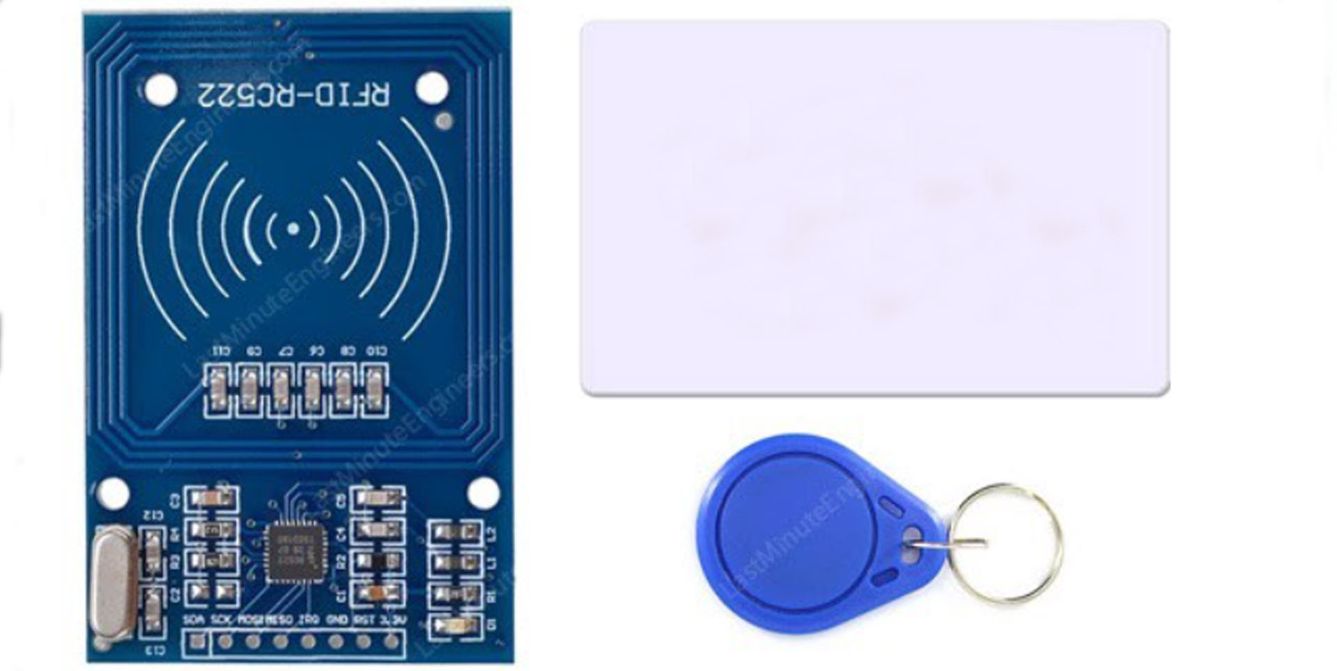
In this assignment, I selected the RFID RC522 module as the input device to explore its functionality and measure its performance. RFID (Radio Frequency Identification) is a widely used technology for reading and writing data to RFID tags, which are passive devices energized by the RFID reader. The RC522 is a compact and cost-effective module that communicates using the SPI protocol and is supported by popular development environments like Arduino.
To integrate the RFID module with my custom-designed microcontroller board, I followed a structured approach that involved understanding the module’s operation, designing an appropriate interface, and writing firmware to interact with the device. This process not only provided insights into how the RFID technology works but also enabled me to apply the principles of microcontroller interfacing.
Hardware Design
The RC522 module operates at 3.3V and requires a stable power supply to function effectively. My custom microcontroller board, which uses an Seedstudio esp32C3, supports both 3.3V and 5V operation. I leveraged the board’s 3.3V output to power the module, ensuring compatibility without requiring additional level-shifting components.
Checked using breadboard to confirm the connections are working fine
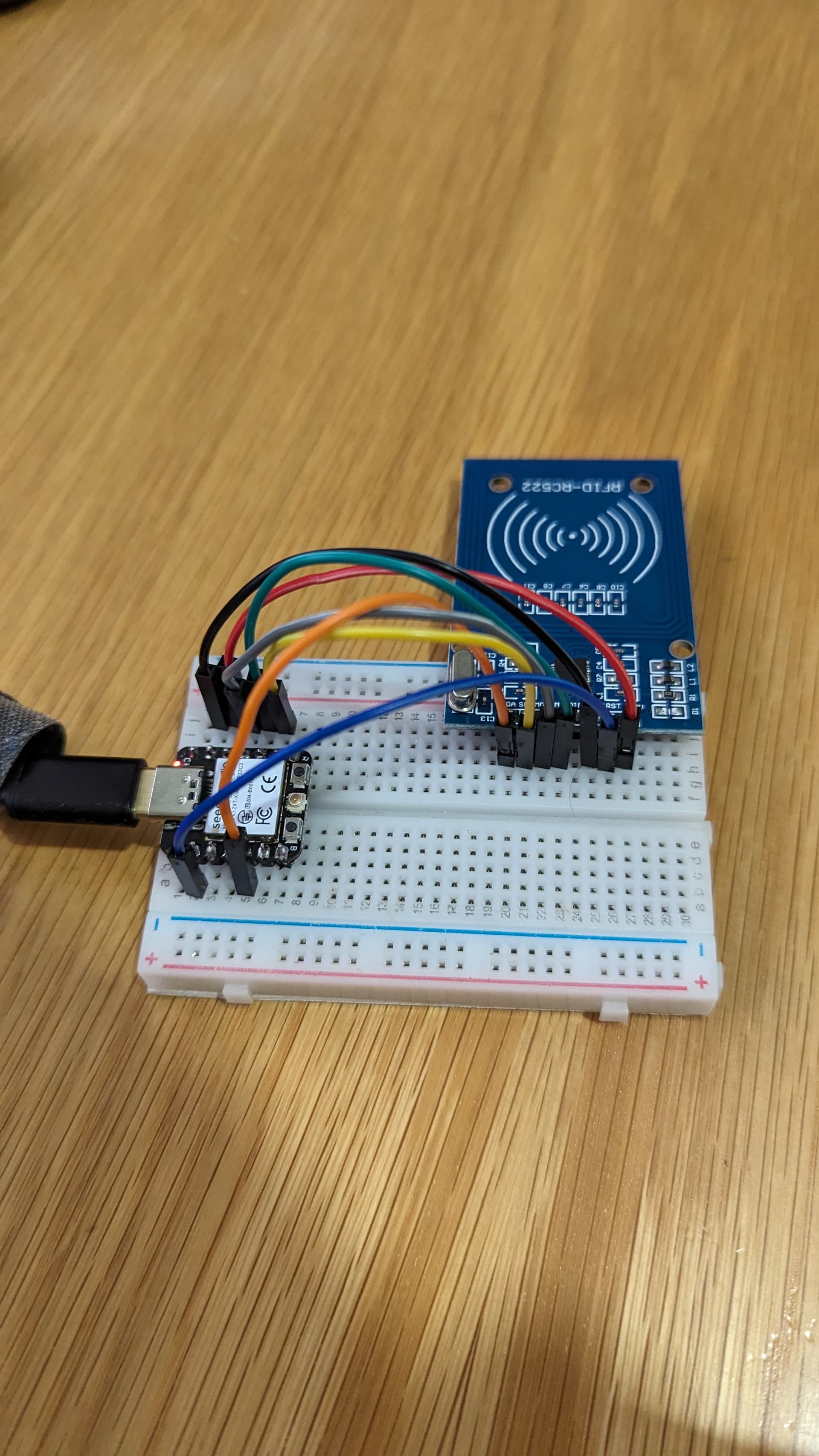
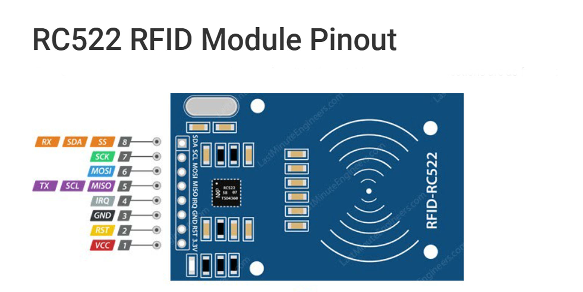
The module communicates with the microcontroller through the SPI (Serial Peripheral Interface) protocol, which is known for its reliability and speed. The necessary connections were as follows:
- SS (Slave Select): Connected to Pin 7 on the microcontroller, this pin enables communication with the module.
- MOSI (Master Out, Slave In): Connected to Pin 10, this line sends data from the microcontroller to the module.
- MISO (Master In, Slave Out): Connected to Pin 9, this line receives data from the module.
- SCK (Serial Clock): Connected to Pin 8, this line provides the clock signal for synchronization.
- RST (Reset): Connected to Pin 2, this pin is used to reset the module during initialization or troubleshooting.
Designing the Workflow
The workflow involved reading the UID (Unique Identifier) of RFID tags and comparing it with predefined UIDs stored in the microcontroller’s firmware. When a tag is brought near the module’s antenna, the module reads its UID and sends this information to the microcontroller. The firmware then checks if the UID matches any of the authorized IDs and performs the appropriate action.
To test the module’s operation, I wrote a program using the Arduino IDE and the MFRC522 library. The program initializes the RFID
module, continuously checks for a new tag, and reads its UID. The UID is then compared to a predefined target UID. If a match is found, a message
indicating “Access Granted” is displayed. If no match is found, the program displays
“Access Denied.”
Design and Fabrication Process
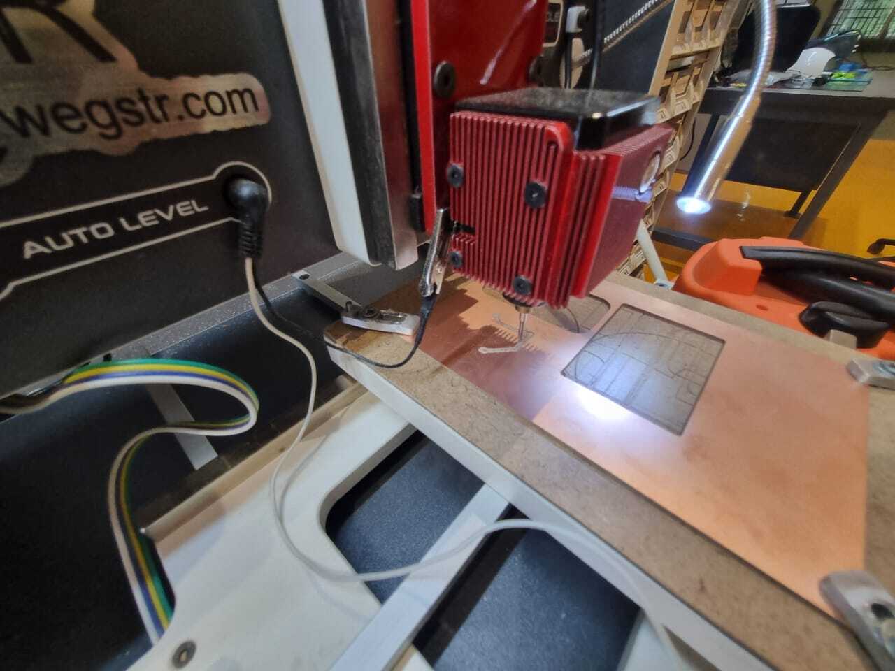
The RFID reader module (RC522) was integrated with a custom microcontroller board that I designed using KiCad. The board is based on the ESP32 microcontroller and was fabricated by Wegstr using their high-quality PCB manufacturing services. Careful planning ensured reliable communication, power delivery, and overall system robustness.
The connection between the RFID module and the microcontroller was established via the SPI communication interface, consisting of four key lines: MISO (Master In Slave Out), MOSI (Master Out Slave In), SCK (Serial Clock), and SS (Slave Select). These lines enabled fast and synchronous data exchange, essential for reading RFID tags accurately.
In addition to the SPI signals, the RFID module required a stable 3.3V power supply, provided by the custom board’s onboard voltage regulator. The RST (reset) pin was connected to a microcontroller I/O pin for resetting the module through firmware, ensuring robust operation.
KiCad was used for schematic capture and PCB layout design. Special attention was given to minimizing the SPI signal line lengths to reduce noise and maintain signal integrity. Decoupling capacitors were strategically placed near the power pins of the microcontroller and the RFID module to filter voltage spikes and noise.
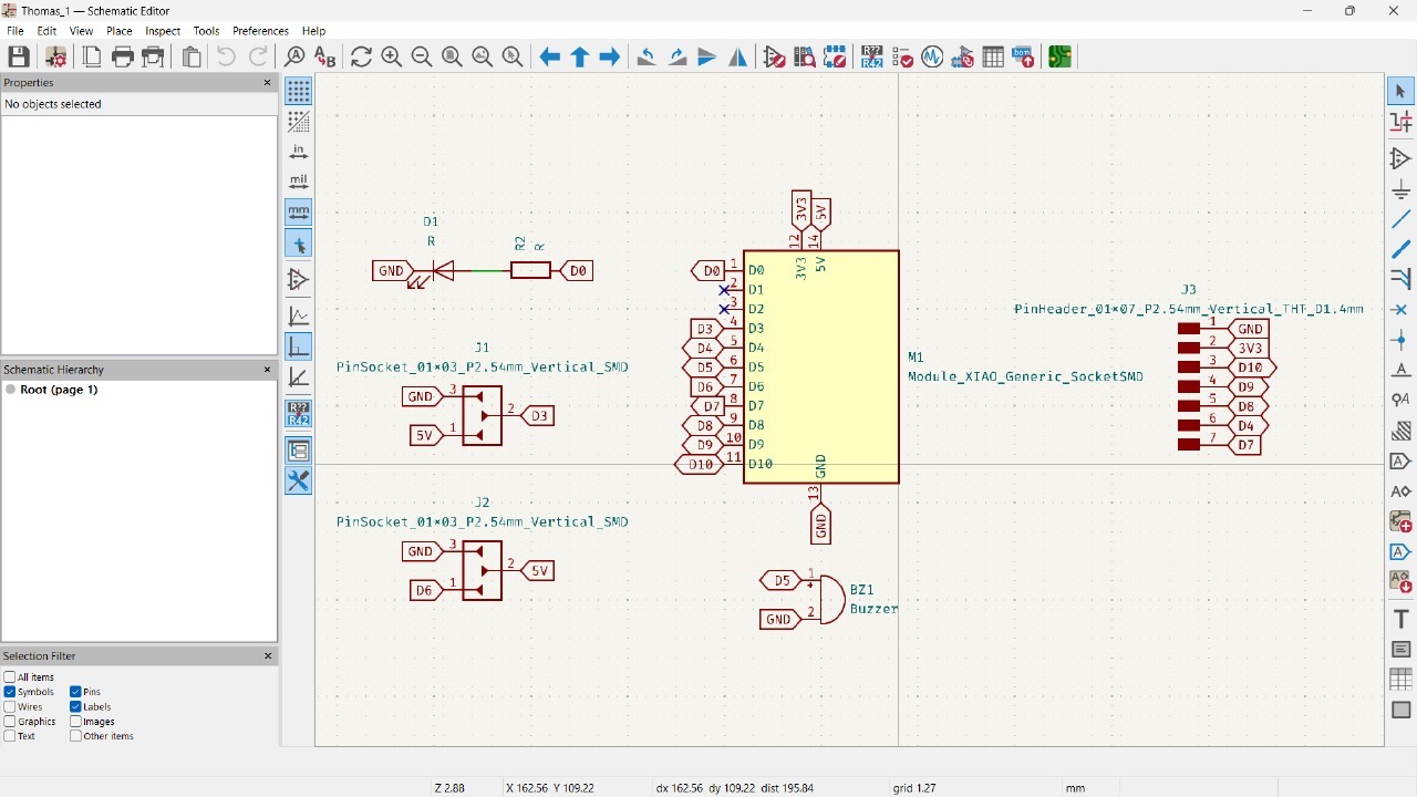
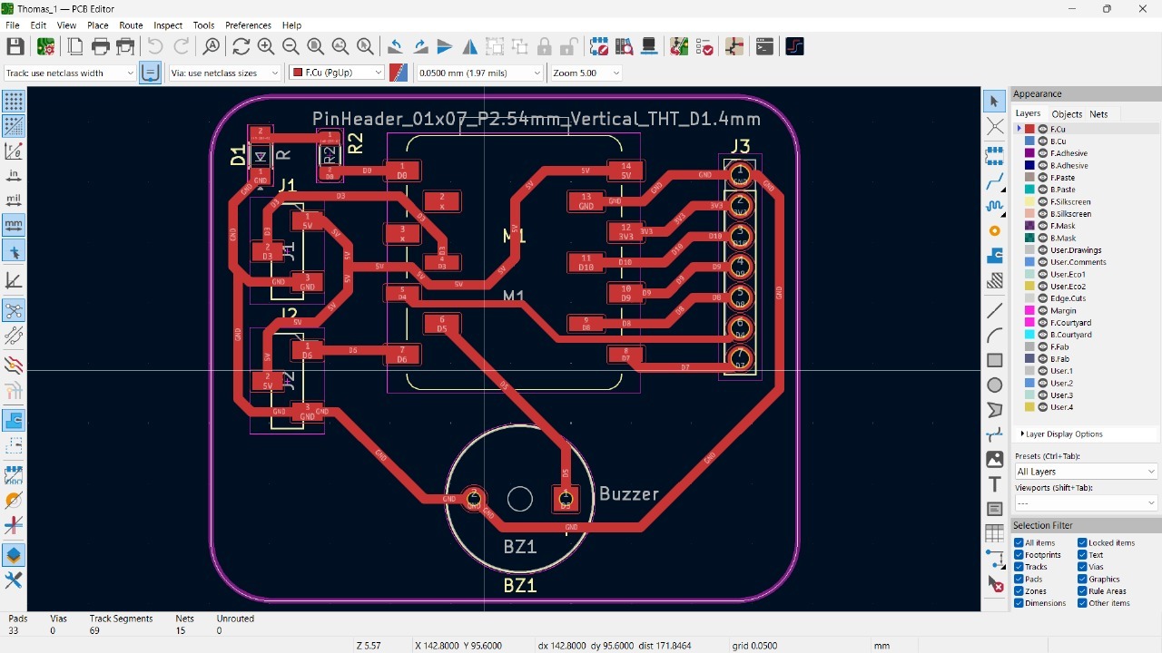
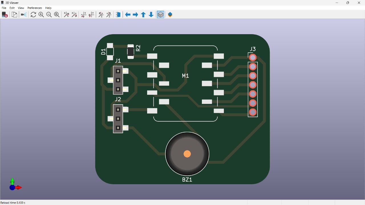
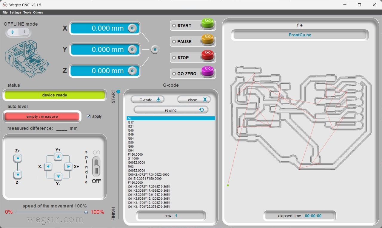
After finalizing the PCB design in KiCad, the Gerber files were uploaded to Wegstr for fabrication. The high-quality boards were delivered promptly, after which components were soldered, including the microcontroller, crystal oscillator, voltage regulator, connectors, and a socket for the RFID module.
Firmware development followed hardware assembly, involving the initialization of the SPI interface, configuration of the RFID module, and coding for tag reading and peripheral control. Debugging was performed using serial output and oscilloscope signals to verify communication and troubleshoot issues effectively.
3. Programming Process
The RFID RC522 module was programmed using the Arduino IDE and the MFRC522 library. The programming process involved initializing the RFID module,
detecting tags, and reading their unique identifiers (UIDs). The firmware also handled decision-making based on whether the scanned tag matched a predefined UID.
Below is a snippet of the code used to read the RFID tags:
#include#include #define SS_PIN 7 #define RST_PIN 2 MFRC522 rfid(SS_PIN, RST_PIN); // Create an instance of the MFRC522 class byte targetUID[4] = {0xC3, 0x76, 0xDF, 0x26}; // Target UID for authentication void setup() { Serial.begin(9600); // Initialize serial communication SPI.begin(); // Initialize SPI bus rfid.PCD_Init(); // Initialize the RFID module Serial.println("Place your card near the reader."); } void loop() { if (!rfid.PICC_IsNewCardPresent()) { return; // No new card detected } if (!rfid.PICC_ReadCardSerial()) { return; // Unable to read the card } Serial.print("UID: "); for (byte i = 0; i < rfid.uid.size; i++) { Serial.print(rfid.uid.uidByte[i], HEX); Serial.print(" "); } Serial.println(); if (isUIDMatch(rfid.uid.uidByte, rfid.uid.size)) { Serial.println("Access Granted"); } else { Serial.println("Access Denied"); } rfid.PICC_HaltA(); // Halt communication with the card rfid.PCD_StopCrypto1(); // Stop encryption on the reader } bool isUIDMatch(byte *uid, byte size) { if (size != 4) { return false; } for (byte i = 0; i < 4; i++) { if (uid[i] != targetUID[i]) { return false; } } return true; }
This code snippet demonstrates the essential steps for using the RFID RC522 module. It initializes the hardware, detects RFID tags, and reads their UIDs.
The isUIDMatch function is used to verify whether the scanned UID matches the predefined target UID. If a match is found, access is granted; otherwise, access is denied.
The programming process also included handling errors such as communication issues and ensuring smooth operation by implementing reset mechanisms for the RFID module.
By leveraging the MFRC522 library, the development process was simplified, allowing me to focus on the core functionality.
4. Problems Encountered and Fixes
Initially, there were issues with SPI communication due to incorrect wiring. This was resolved by checking the pin assignments and ensuring secure connections.
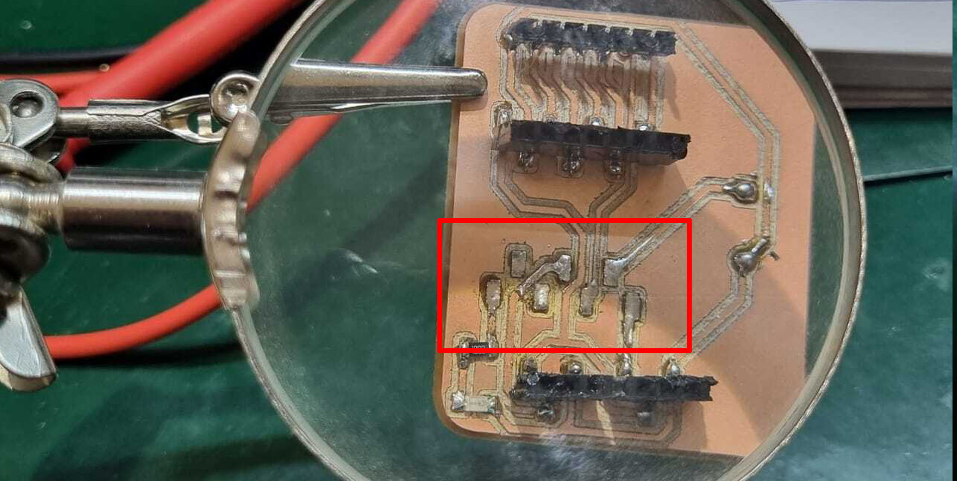
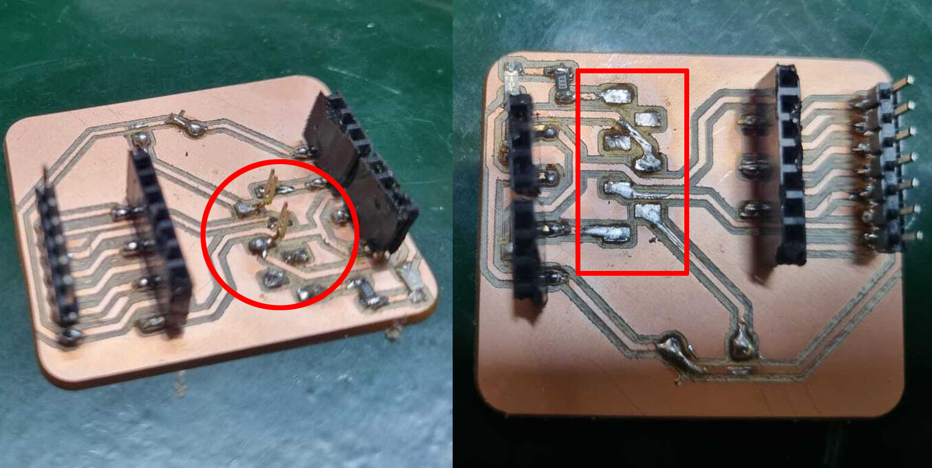
Due to soldering issue we were getting continuity in 3 pins we had to remove the old solder and rearrange the tracks to solve the issue.
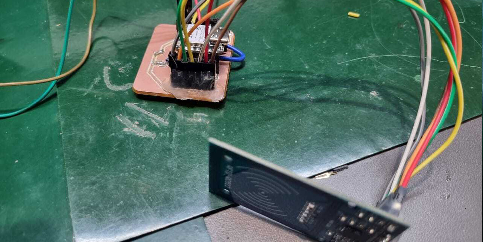
5. Hero Shot
Challenges and Solutions
During the integration process, several challenges were encountered. The most significant was ensuring a stable power supply to the RFID module. Intermittent resets were observed.
Another challenge was the occasional communication error between the module and the microcontroller. High-frequency noise on the SPI lines caused these errors. To mitigate this issue, I used shorter connecting wires and ensured that the SPI lines were shielded from external interference. These measures improved the reliability of data transmission.
Results
The RFID RC522 module performed reliably after addressing the initial challenges. It successfully read RFID tags and transmitted their UIDs to the
microcontroller. The firmware efficiently handled the comparison process and provided appropriate feedback, demonstrating the module’s accuracy and
responsiveness.
The RFID reader module (RC522)
Seedstudio_ESP32C3 (ESP32C3)
Design and Fabrication Process
This assignment not only highlighted the capabilities of the RFID RC522 module but also reinforced the importance of designing robust power supplies and reliable communication interfaces. The insights gained from this project will be invaluable for future applications involving input devices and microcontrollers.