Week 4: Embedded Programming
Exploring Embedded Architectures
This group assignment delves into the fascinating world of embedded systems, focusing on the toolchains and development workflows across various embedded architectures. By analyzing and comparing these workflows, we aim to identify key advantages, challenges, and best practices for efficient development in embedded environments.
Visit our Group Assignment Page to explore our findings and methodologies.
1. Browsed and Documented Information from Microcontroller's Datasheet
ESP32 Microcontroller Overview
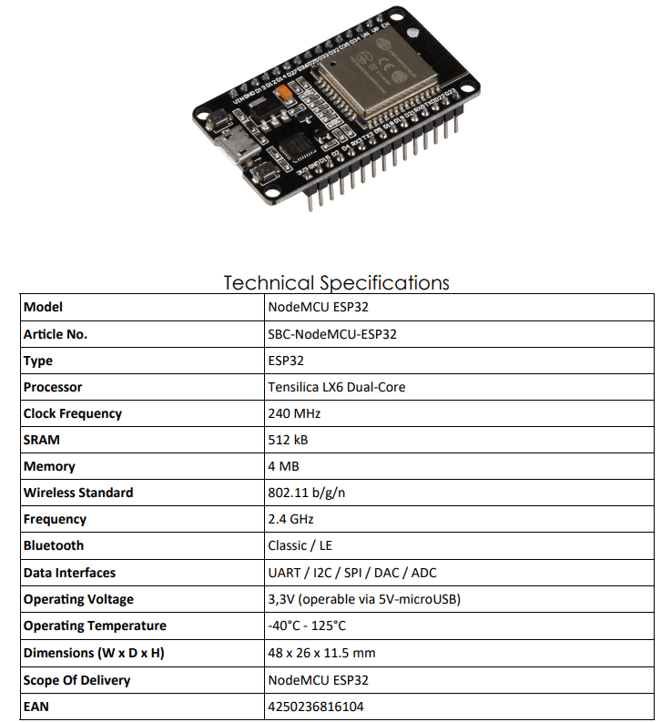
The ESP32 is a powerful, low-cost microcontroller with integrated Wi-Fi and Bluetooth connectivity, widely used in IoT projects. It offers high performance with multiple cores, versatile peripherals, and flexible power management, making it suitable for embedded applications.
- Processor:
The ESP32 features a dual-core Tensilica LX6 microprocessor with clock speeds up to 240 MHz, providing robust computational power for multitasking and complex applications.
- Memory:
Includes 448 KB of internal RAM and supports external SPI flash memory, typically 4 MB or more, for program storage and data buffering.
- Wireless Connectivity:
Integrated Wi-Fi (802.11 b/g/n) and Bluetooth 4.2 (Classic and BLE) for seamless wireless communication in IoT and embedded devices.
- Power Management:
Supports multiple low-power modes with dynamic voltage and frequency scaling to optimize energy consumption, suitable for battery-powered applications.
- Peripherals:
Includes rich I/O interfaces such as:
- GPIO pins (up to 34 configurable pins)
- ADC (12-bit, up to 18 channels)
- DAC (2 channels)
- SPI, I2C, UART communication interfaces
- Touch sensors, PWM outputs, CAN bus
- Security Features:
Hardware acceleration for encryption (AES, SHA-2, RSA), secure boot, and flash encryption for protecting firmware and data integrity.
- Operating Voltage:
Typically operates at 3.3V with integrated regulators and brownout detection to ensure stability.
- Package:
Available in multiple package types such as QFN and WLCSP, supporting compact and varied design requirements.
The ESP32's combination of processing power, connectivity, and peripheral options makes it a versatile microcontroller choice for wireless-enabled embedded systems.
2. Programming the ESP32 with Ardunio IDE
Programming the ESP32 with Arduino IDE
Programming the ESP32 microcontroller using the Arduino IDE provides a simple and accessible environment for developing IoT and embedded applications. The Arduino IDE supports familiar syntax and extensive libraries, enabling rapid prototyping.
- Step 1: Install Arduino IDE
Download and install the latest Arduino IDE from the official Arduino website. It is available for Windows, macOS, and Linux.
- Step 2: Add ESP32 Board Support
Configure the Arduino IDE to support ESP32 boards:
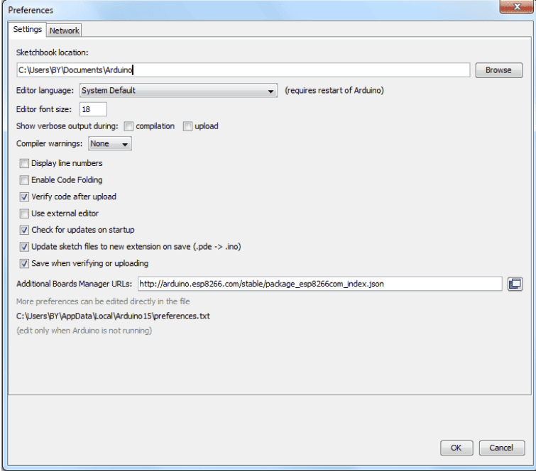
- Go to File > Preferences and add the ESP32 boards URL (
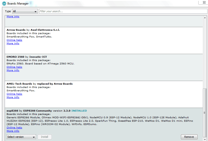
https://raw.githubusercontent.com/espressif/arduino-esp32/gh-pages/package_esp32_index.json) in the “Additional Board Manager URLs” field. - Open Tools > Board > Boards Manager, search for “ESP32,” and install the “esp32” package by Espressif Systems.
- Go to File > Preferences and add the ESP32 boards URL (
- Step 3: Select ESP32 Board
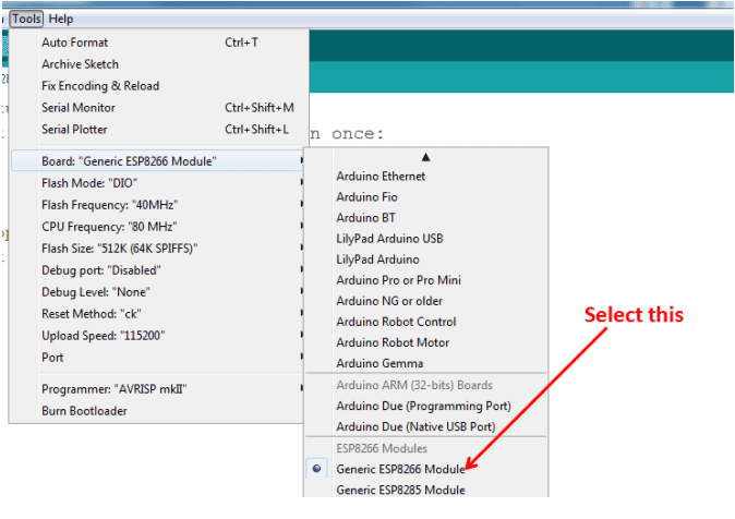
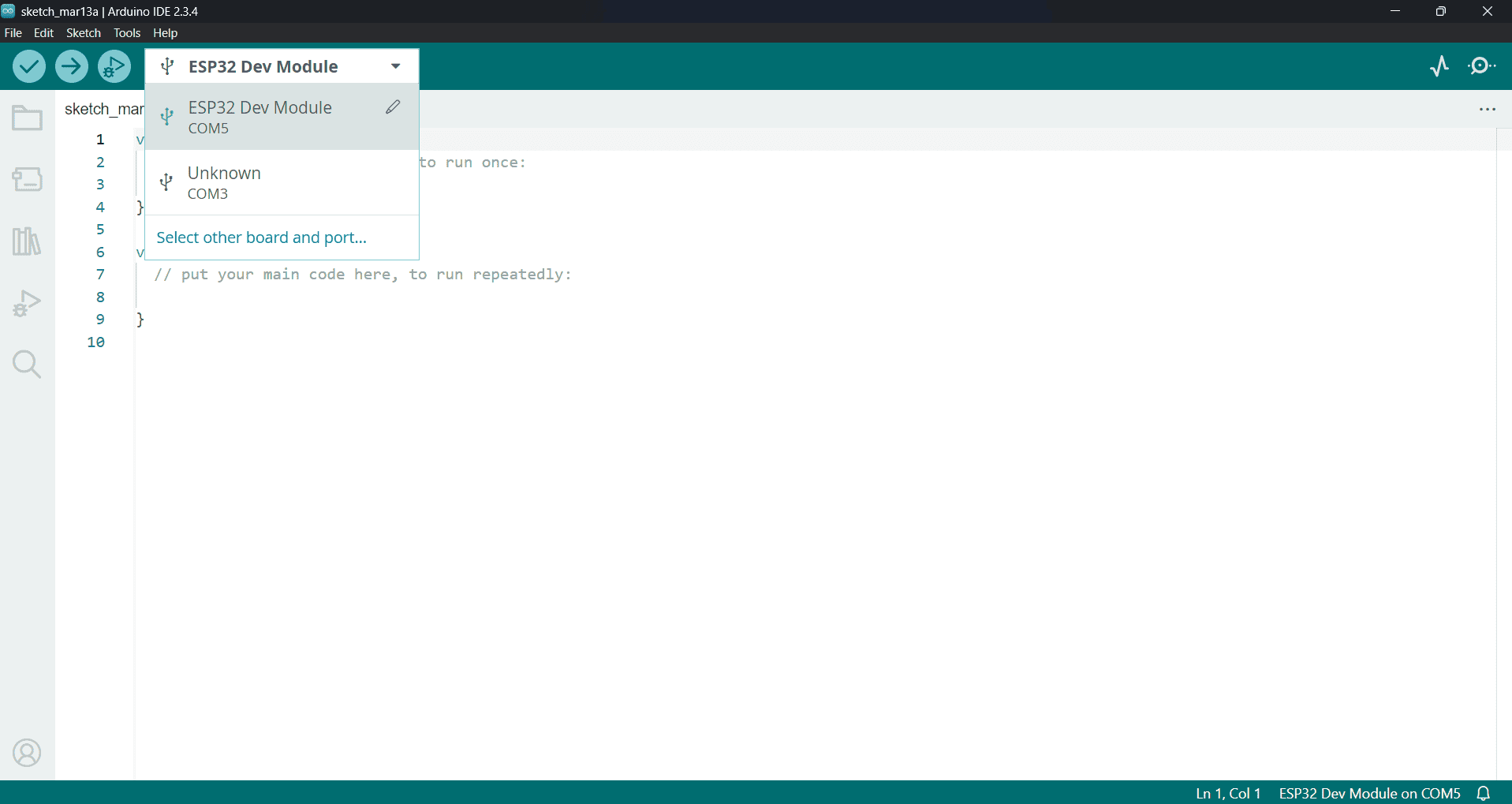
In the Arduino IDE, navigate to Tools > Board and select the specific ESP32 board model you are using (e.g., “ESP32 Dev Module”).
- Step 4: Connect the ESP32
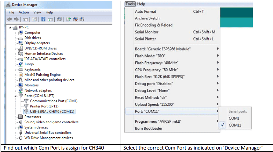
Use a USB cable to connect the ESP32 board to your computer. Ensure the correct COM port is selected under Tools > Port.
- Step 5: Write or Load a Sketch
Write your own Arduino sketch or load example code by navigating to File > Examples > ESP32. Basic examples include Wi-Fi connectivity, GPIO control, and Bluetooth.
- Step 6: Configure Settings
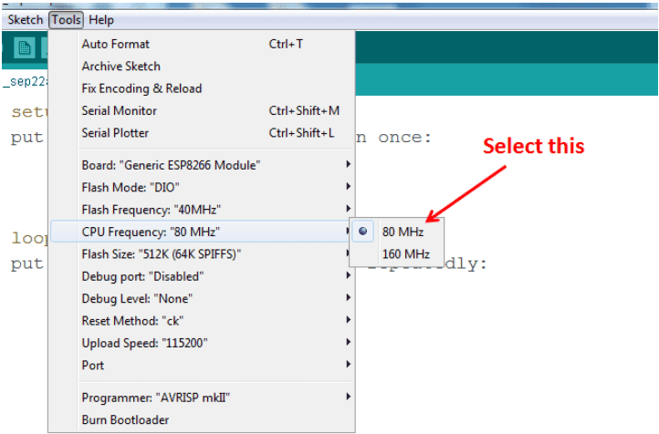
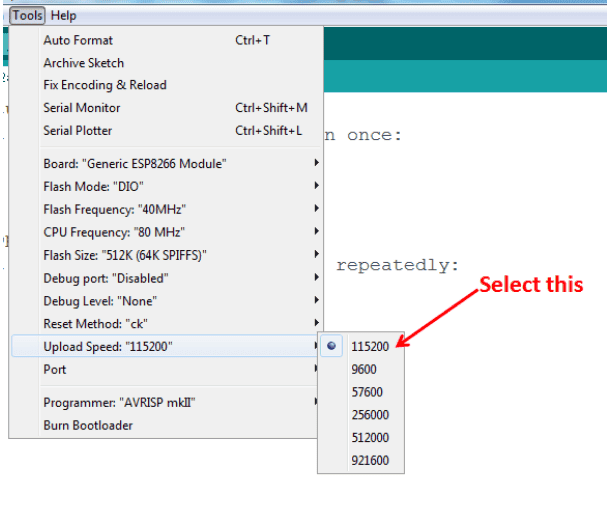
Adjust settings such as upload speed and partition scheme in Tools as required by your project.
- Step 7: Compile and Upload
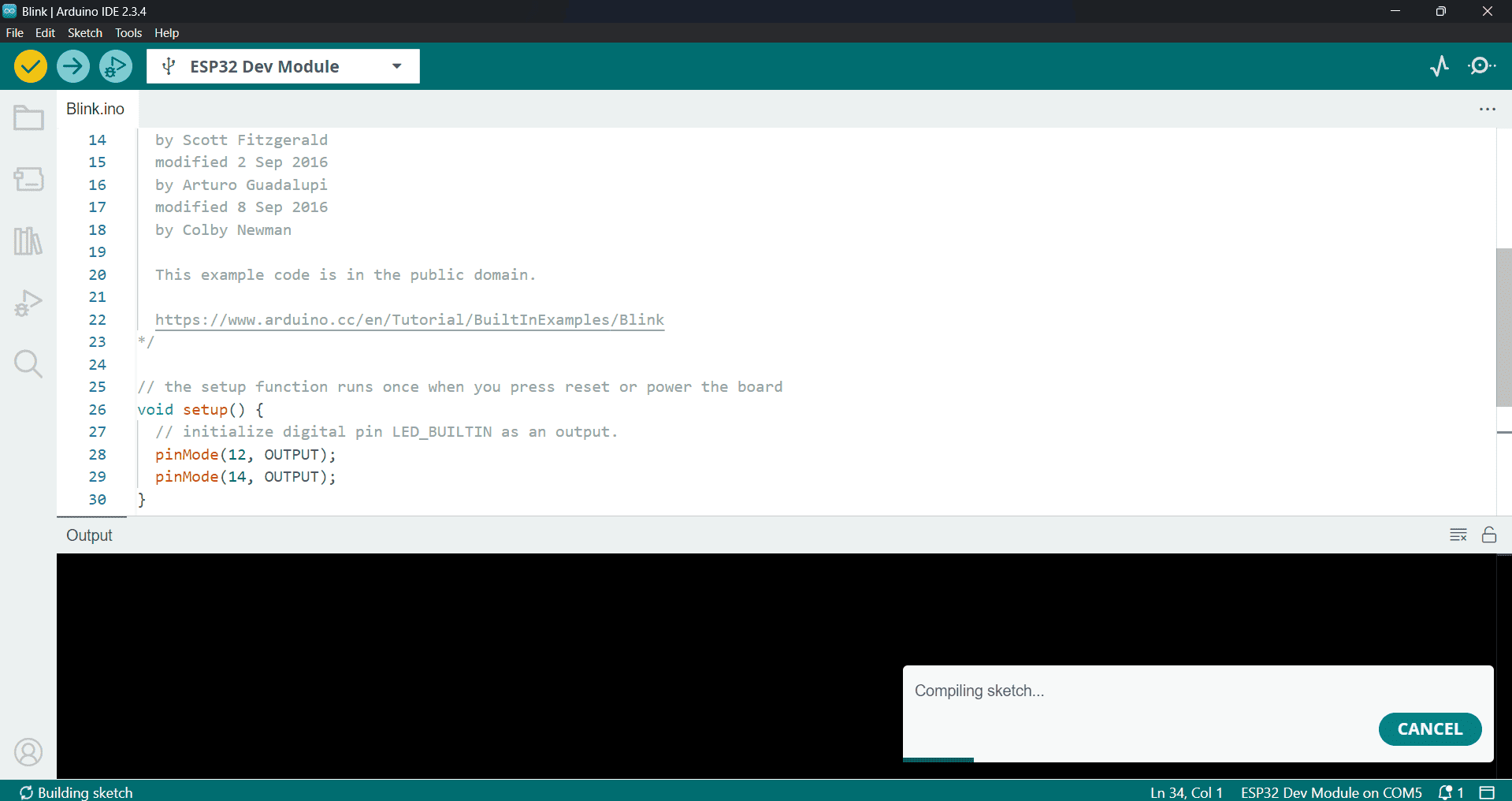
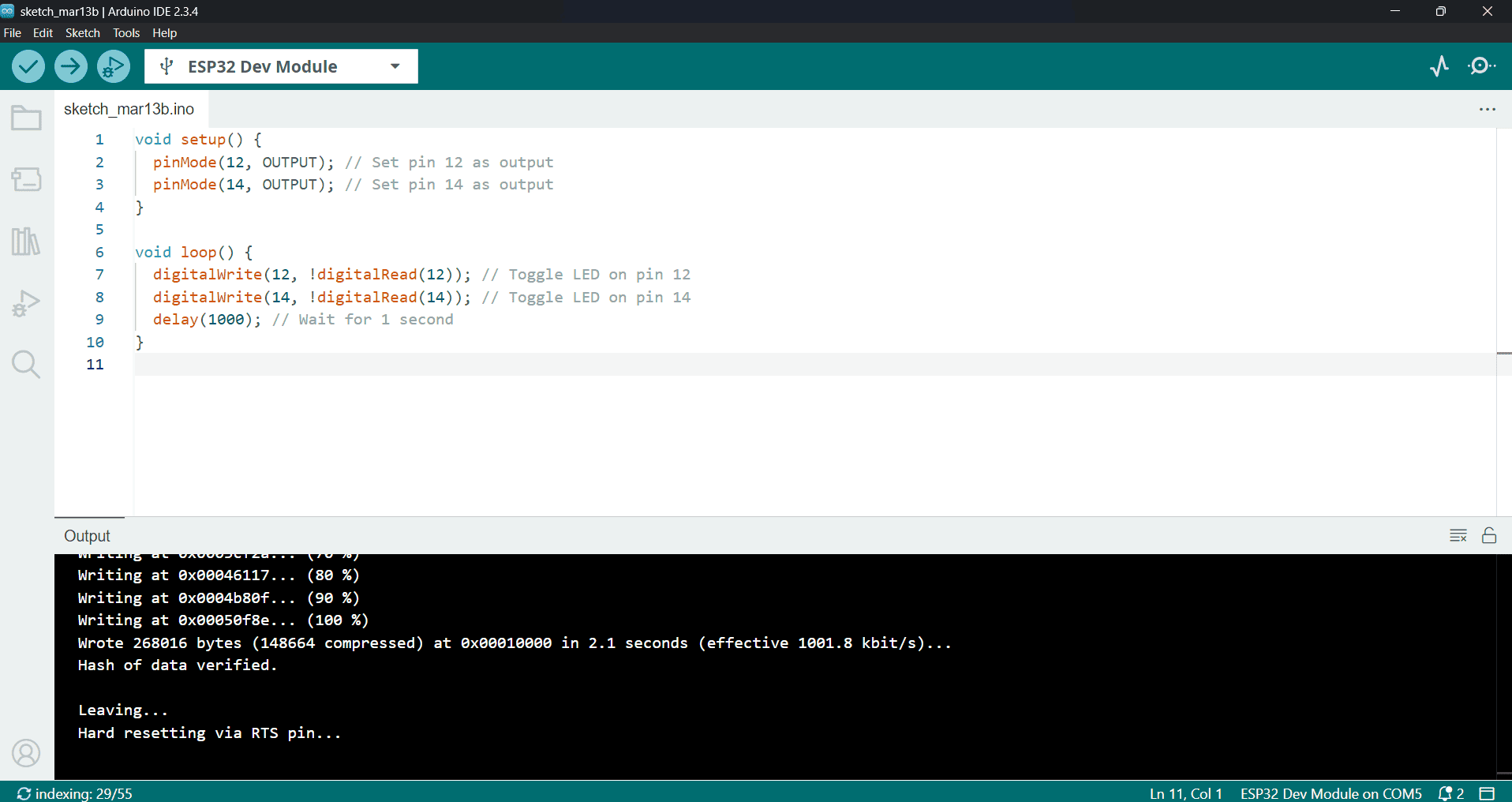
Click the Verify button to compile your code and then Upload to flash the program to the ESP32. The IDE will show progress and notify you of success or errors.
- Step 8: Monitor Serial Output
Open the Serial Monitor (Tools > Serial Monitor) to view debug messages or output from your ESP32 application. Set the baud rate to match your sketch (usually 115200).
- Step 9: Debug and Iterate
Modify your code as needed, recompile, and upload to refine your application.
Using Arduino IDE to program the ESP32 simplifies the development process, allowing beginners and professionals to quickly build and deploy wireless-enabled embedded systems.
3. Wiring the Hardware
Wiring the ESP32 Hardware
Proper wiring of the ESP32 microcontroller is essential to ensure reliable operation and seamless communication with external components like sensors, actuators, and peripherals. Below are the key steps and considerations for wiring the ESP32 hardware:
- Step 1: Power Supply
Provide a stable 3.3V power supply to the ESP32:
- The ESP32 operates at 3.3V and is not 5V tolerant on its I/O pins.
- If using a 5V power source, use a voltage regulator or a development board with built-in regulation.
- Connect the 3.3V output to the ESP32's 3.3V pin and ground to GND.
- Step 2: Ground Connections
Connect all grounds (ESP32, sensors, power supply) together to establish a common reference point, which is crucial for stable communication.
- Step 3: GPIO Pin Usage
Connect external components to the ESP32's General Purpose Input/Output (GPIO) pins:
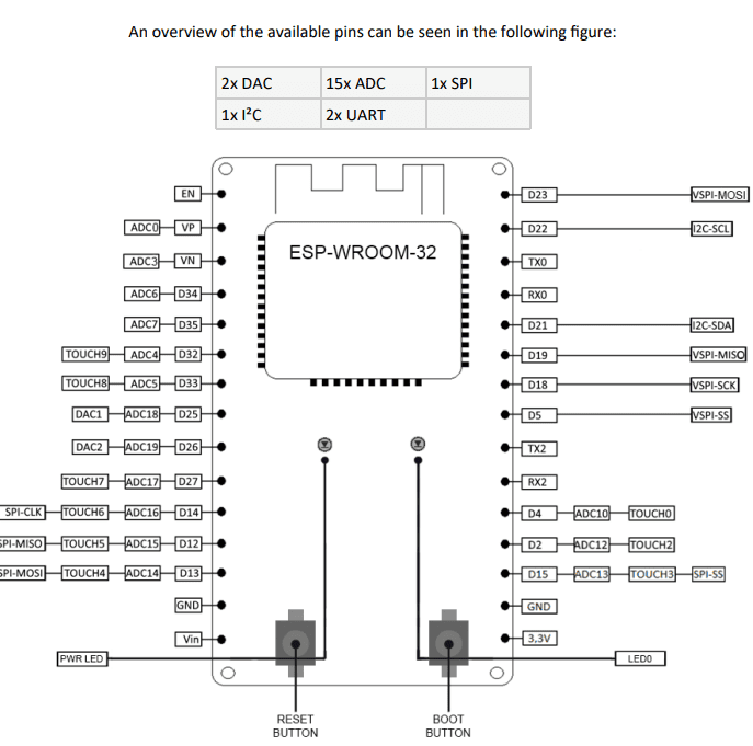
- Check the ESP32 datasheet or pinout diagrams to identify pins suitable for input, output, ADC, PWM, or communication interfaces.
- Avoid pins reserved for special functions (e.g., boot mode pins) unless necessary.
- Use pull-up or pull-down resistors as needed to stabilize inputs.
- Step 4: Communication Interfaces
Wire communication protocols according to your peripherals:
- I2C: Connect SDA and SCL lines to ESP32’s I2C pins with pull-up resistors (typically 4.7 kΩ).
- SPI: Connect MOSI, MISO, SCK, and CS pins appropriately.
- UART: Connect RX and TX pins for serial communication, cross-connecting RX to TX and vice versa.
- Step 5: Analog Inputs
When connecting analog sensors, wire the sensor output to ESP32 ADC-capable pins. Ensure the sensor voltage does not exceed 3.3V.
- Step 6: Avoid Damage
Take precautions to prevent damage:
- Never apply voltages higher than 3.3V to GPIO pins.
- Use level shifters when interfacing with 5V logic devices.
- Double-check connections before powering the circuit.
- Step 7: Optional Components
Include optional hardware for enhanced functionality:
- Reset button connected to EN pin for manual reset.
- Boot button connected to GPIO0 for flashing mode.
- Decoupling capacitors near the power pins to stabilize voltage.
By carefully wiring the ESP32 following these guidelines, you ensure stable operation, protect the microcontroller from damage, and set a solid foundation for your embedded projects.
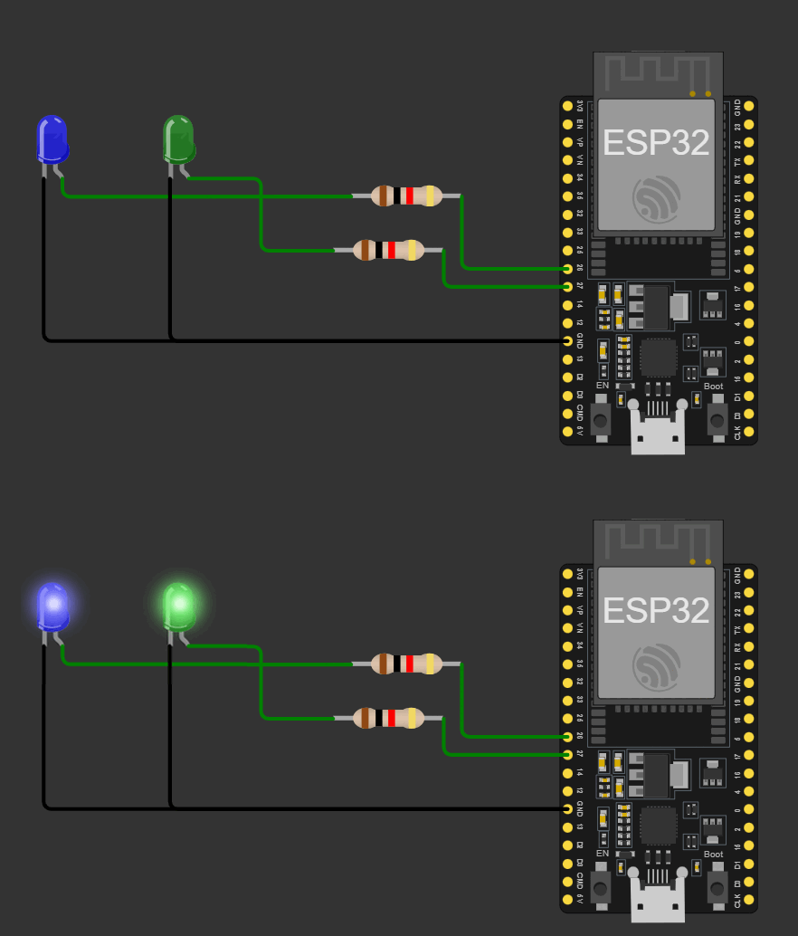
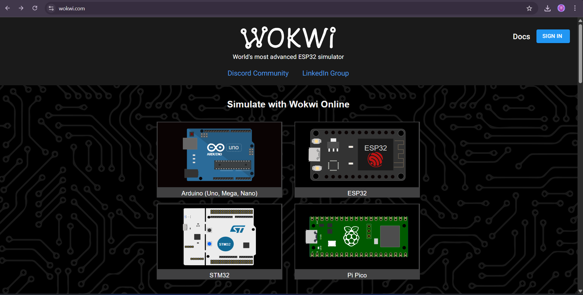
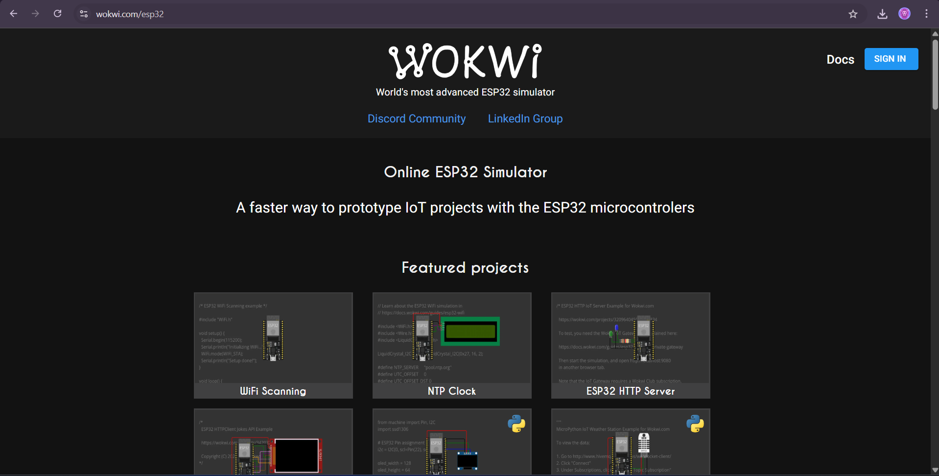
I Have used wokwi Online Simulation platform for stimulating the esp32 since most of the other platforms don't have a simulation for ESP32
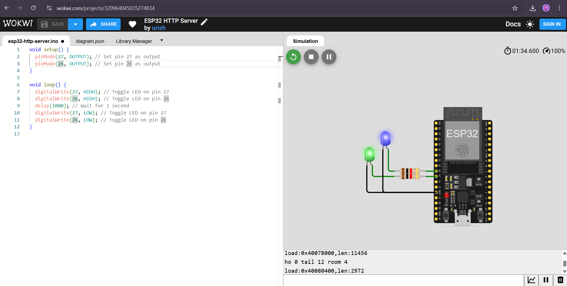
Blink
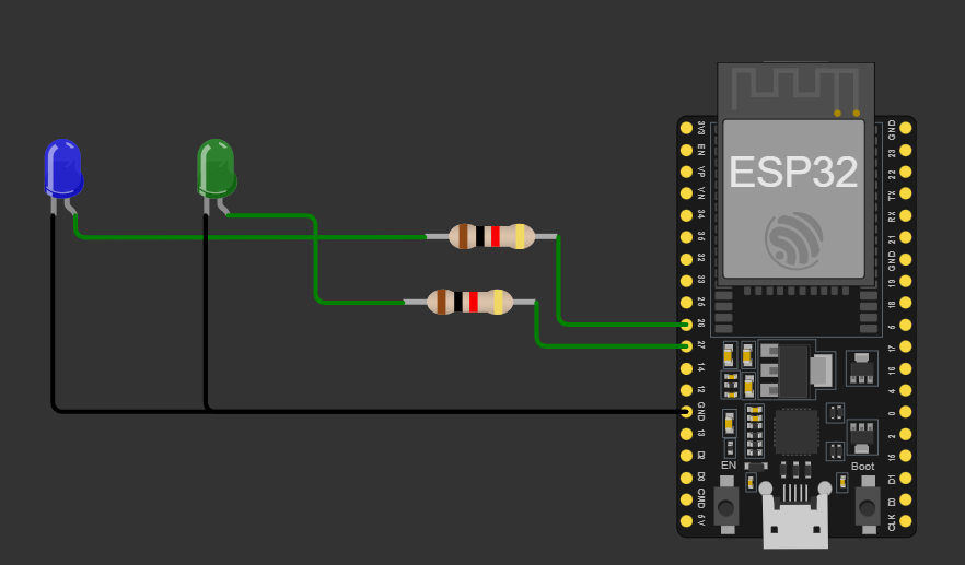
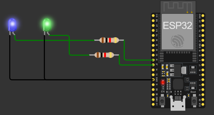
4.Source Code for Blink
void setup() {
  pinMode(27, OUTPUT); // Set pin 27 as output
  pinMode(26, OUTPUT); // Set pin 26 as output
}

void loop() {
  digitalWrite(27, !digitalRead(12)); // Toggle LED on pin 27
  digitalWrite(26, !digitalRead(14)); // Toggle LED on pin 26
  delay(1000); // Wait for 1 second
}
