Week 3: Computer-Controlled Cutting Assignment
Group Assignment
Lab Safety Training
Completed the lab safety training and documented safety protocols, including emergency procedures, PPE use, and equipment maintenance.
Visit our Group Assignment Page to explore our findings and methodologies.
Characterizing the Laser Cutter
- Focus: Optimal focus setting achieved by testing with acrylic.
- Power and Speed: Documented ideal settings for wood and cardboard.
- Kerf: Measured kerf at 0.2mm for 3mm plywood.
- Joint Clearance: Best fit achieved with 0.25mm clearance.
Individual Assignment
Vinyl Cutter
Designed and cut a custom logo on the vinyl cutter. Applied to a notebook cover.
Parametric Construction Kit
Designed and laser-cut a parametric construction kit with multiple assembly options. Accounted for laser kerf.
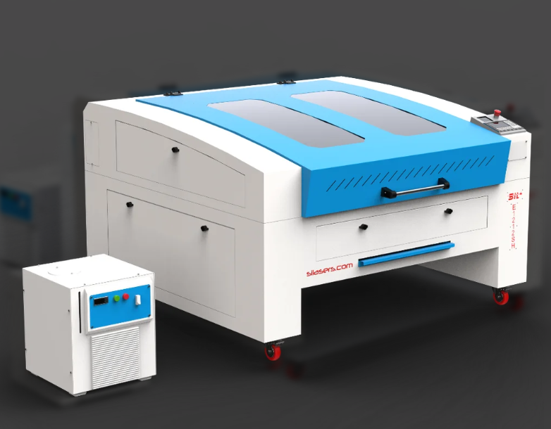
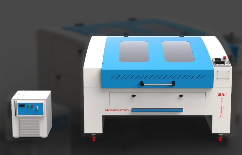
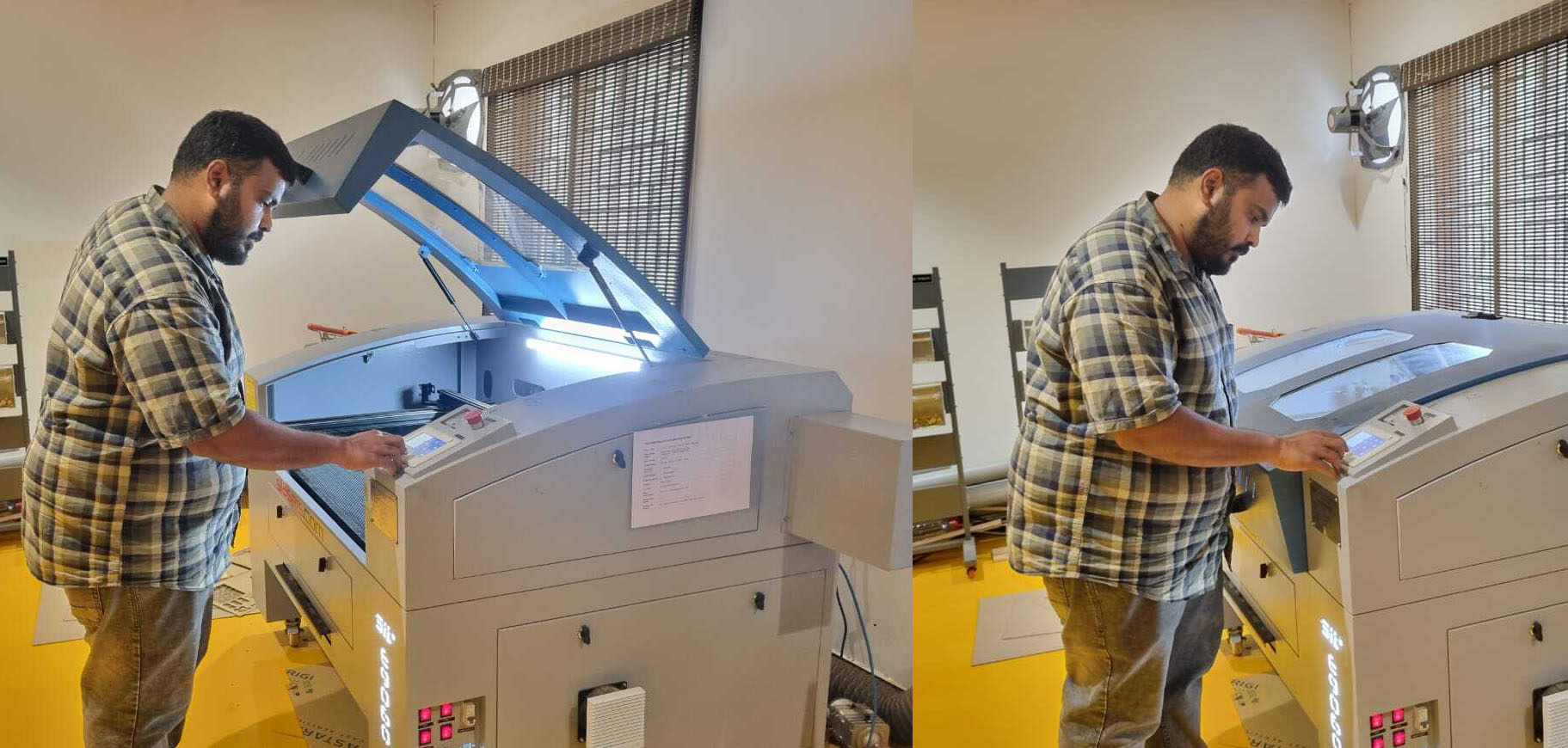
Detail about the Laser Sil 6090:
SIL Laser Engraving Machines
SIL laser engraving machines are versatile tools designed for a wide range of industrial and creative applications. These machines are manufactured in India and cater to diverse industries such as signage, indoor and outdoor advertising, art, crafts, gifts, footwear, toys, garments, model cutting, packaging, wood and MDF cutting, interior decoration, and more.
- Applications: Ideal for industries ranging from signage and advertising to packaging and interior decoration.
- Manufacturing: Engineered and manufactured entirely in India to meet global standards.
Laser Types
SIL laser systems offer two main laser configurations to suit various user needs:
- Glass Tube Lasers:
- High-quality and compact design.
- Warranty: 6 months.
- Affordable and reliable for general use.
- Metal Tube Lasers:
- RF-excited technology with optional water cooling.
- Warranty: 24 months.
- Built for heavy-duty and long-lasting applications.
Technical Features
The machines are equipped with cutting-edge technologies to optimize performance:
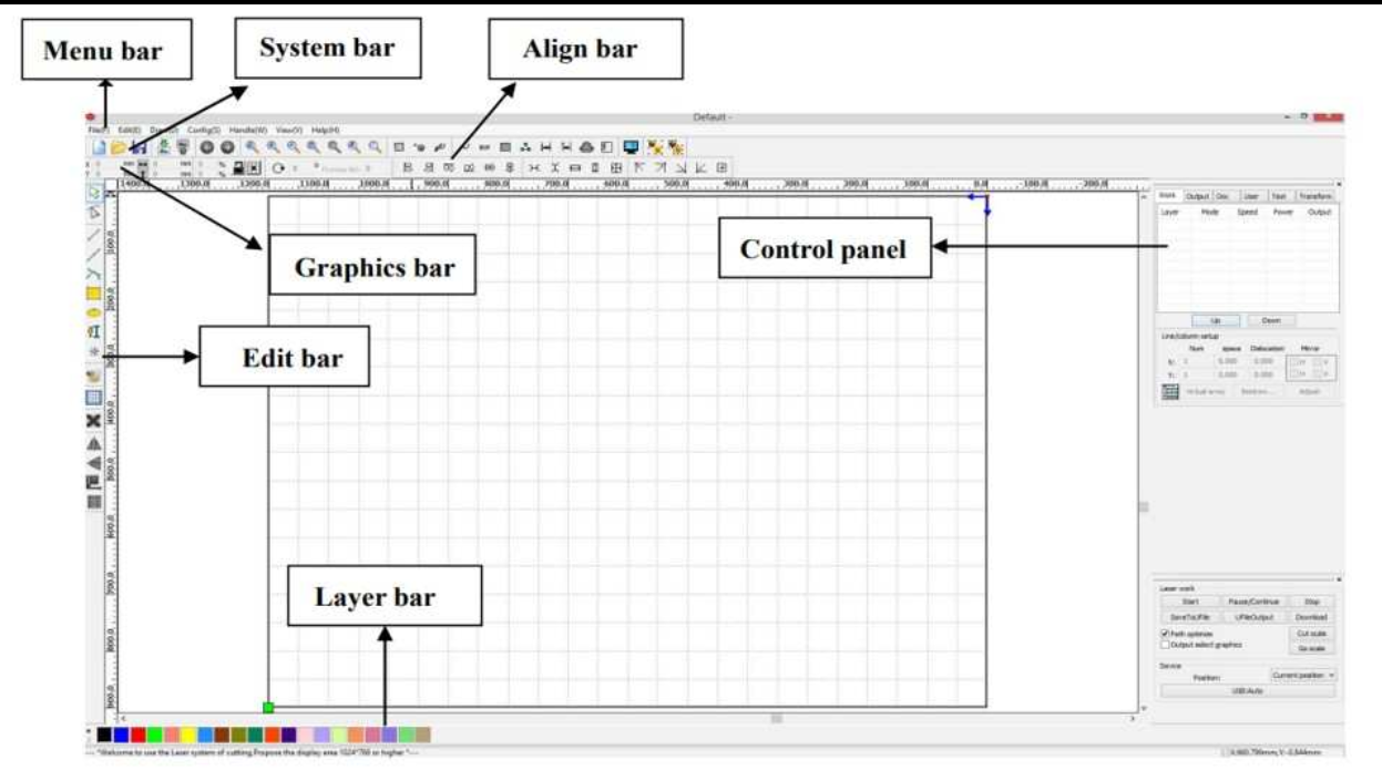
- DSP-Based Control System: Enables offline work with 32 MB storage and printer driver software compatible with AutoCAD, CorelDRAW, and Photoshop.
- Advanced Printing and Engraving: Supports real picture printing, deep engraving, and gradient engraving.
- High-Speed Belt Drive: Features precise micro-stepping drives for efficient operation.
- Optional Enhancements: Includes rotary attachments, image auto-tracing cameras, multiple laser heads, and honeycomb worktables.
Performance Advantages
These machines deliver a host of benefits for industrial and creative use:
- Precision and Accuracy: High cutting precision and superior edge quality.
- Efficiency: Cost-effective with consistent results and minimal material waste.
- Versatility: Suitable for cutting, drilling, and engraving various materials with minimal thermal stress.
- Durability: Rugged design ensures prolonged operational life with minimal maintenance.
Additional Features
- Red Beam Pointer: Simplifies alignment and setup for precise operations.
- Z-Axis (Optional): Facilitates multi-layered cutting and engraving.
- Material Processing Tools: Capable of deep engraving, high-detail picture reproduction, and gradient designs.
SIL Laser Machine Specifications
SIL offers a range of laser engraving and cutting machines under the AccuCut series. These machines cater to various industrial needs with different working area options and advanced technical features.
Model Variants
| SPECS/MODEL | AccuCut 1325 | AccuCut 1212 | AccuCut 1390 | AccuCut 6090 | AccuCut 6040 |
|---|---|---|---|---|---|
| Working Area | 1300x2500mm | 1200x1200mm | 1300x900mm | 600x900mm | 600x400mm |
| Laser Type | Co2 DC Glass Laser Tube / RF Metal Laser Tube | ||||
| Laser Power Option |
Glass Tube – 60/80/100/130/150 Watt Metal Tube – 40/60/80/100/200 Watt |
||||
| Wave Length | 10.6 μm | ||||
| Supply Voltage | AC 230 V ±0.05% / AC 415 V ±0.05% | ||||
| Reposition Accuracy | 0.1 mm (Max) | ||||
| Cutting Speed | 0 ~ 30000 mm/min | ||||
| Engraving Speed | 0 ~ 64000 mm/min | ||||
| Cooling | Water Cooled | ||||
| X, Y Axis | LM Guide Rails SIL Brand | ||||
| Work Environment | Temp: 0°C ~ 45°C. Humidity: 5% ~ 95% | ||||
| Acceleration Speed | 1 G | ||||
| Graphic File Support | PLT, CDR, AI, DWG, DST, DXF, BMP, JPEG, TIFF, GIF, PCX | ||||
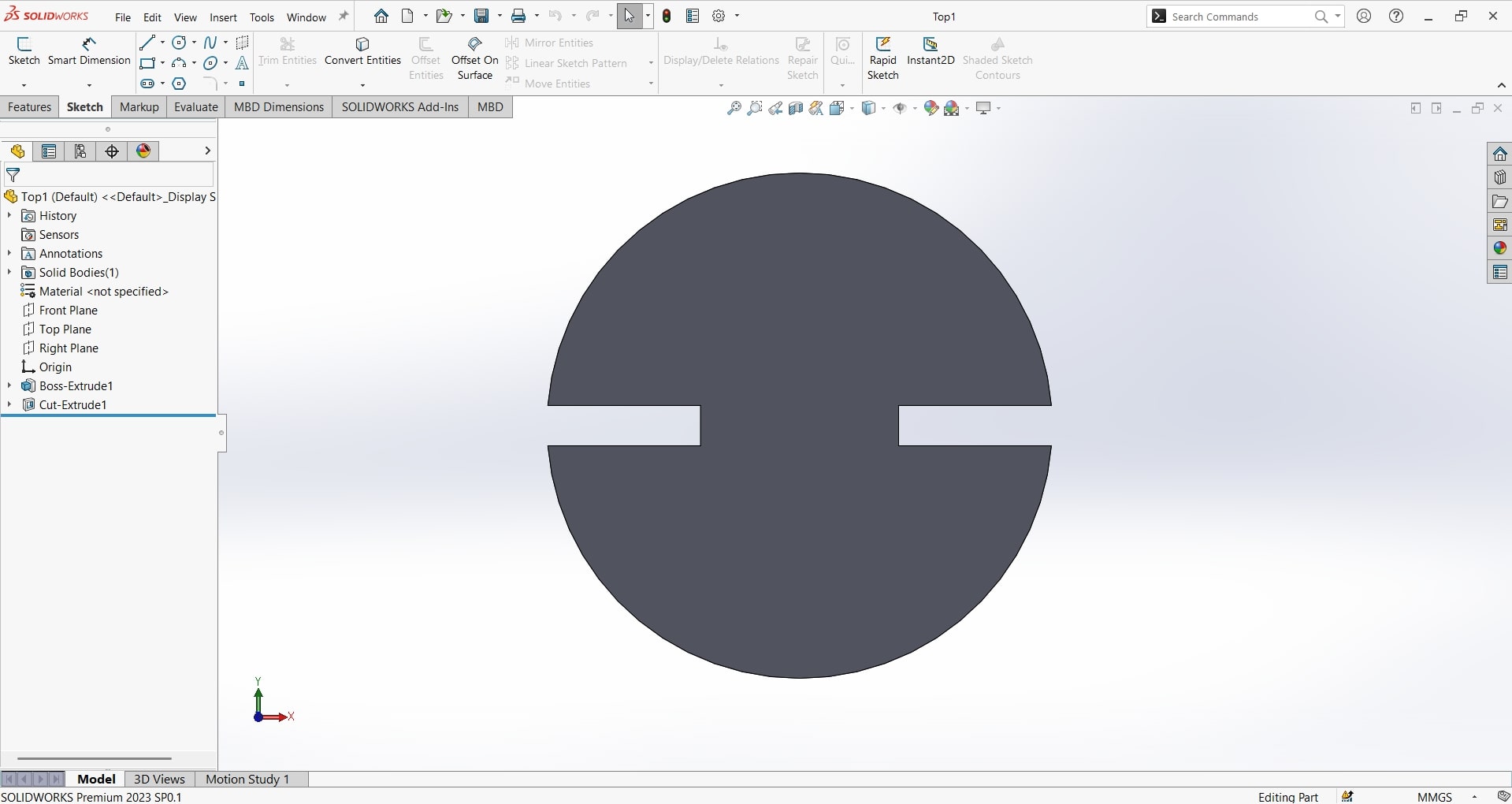
1. Explaination of How I Created My Parametric Design
How to Create a Parametric Design
Parametric design involves creating models where dimensions and geometry are controlled by variables, equations, and constraints. This technique allows for flexible and dynamic designs, enabling changes to propagate throughout the model automatically. Below are the steps to create a parametric design:
- Step 1: Understand the Basics
Parametric design relies on three key components:
- Parameters: Variables like length, width, or height that define dimensions.
- Constraints: Rules that maintain relationships between geometry, such as perpendicularity or symmetry.
- Equations: Mathematical formulas linking parameters to define dependent relationships.
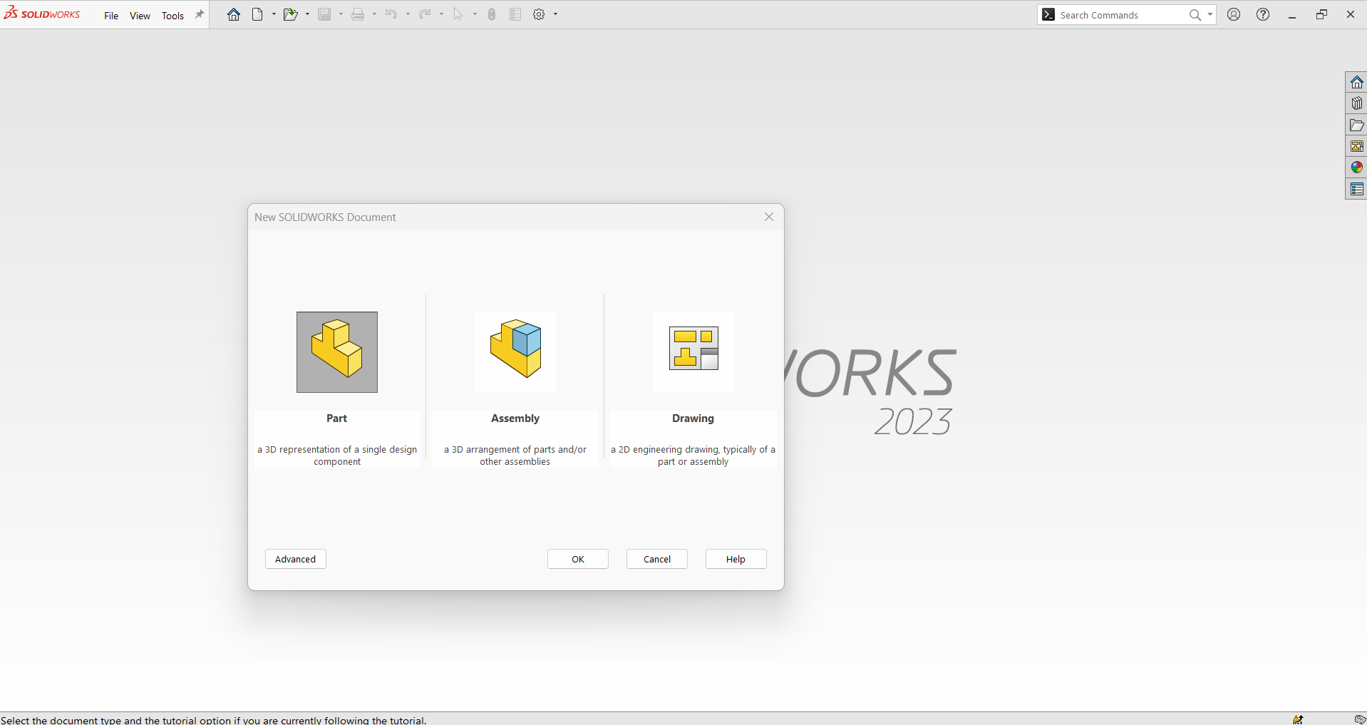
- Step 2: Launch the CAD Software
Open your preferred parametric CAD software, such as SolidWorks, Fusion 360, or AutoCAD. Create a new part or project file to begin designing.
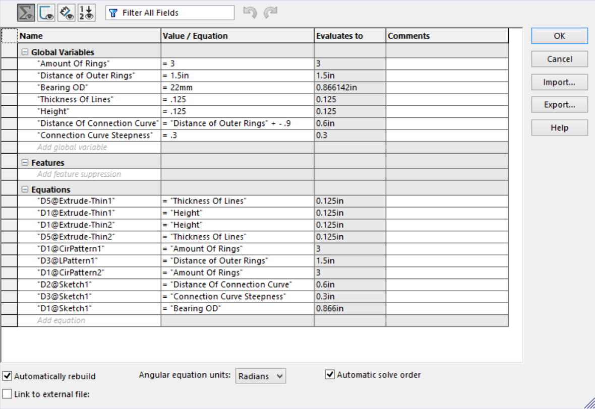
- Step 3: Set Up Parameters
Define the variables that will control your design:
- Access the parameter or equation manager (e.g., “Equations” in SolidWorks).
- Create parameters like “Length = 100 mm” or “Width = 50 mm.”
- Assign meaningful names for clarity, such as “BaseRadius” or “HoleSize.”
- Step 4: Create a 2D Sketch
Start a sketch on a chosen plane (Front, Top, or Right). Draw basic shapes like lines, circles, and rectangles to outline your design. Keep the sketch unconstrained initially to apply parametric rules.
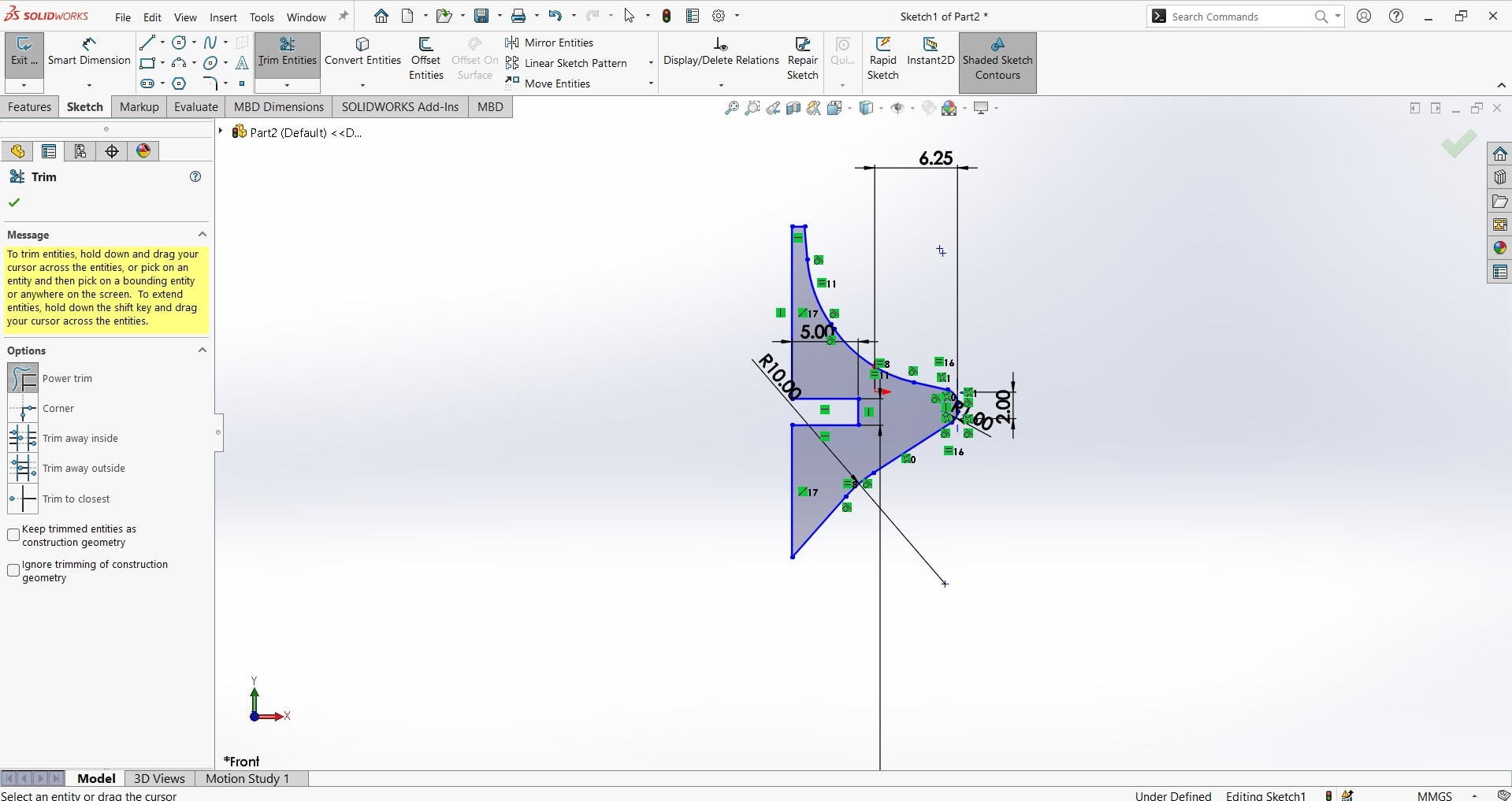
- Step 5: Apply Dimensions and Constraints
Define dimensions and relationships for your geometry:
- Use the “Smart Dimension” tool to add dimensions. Input parameters (e.g., “Length” or “Width”) instead of fixed values.
- Apply geometric constraints such as parallelism, perpendicularity, or tangency to control relationships between sketch elements.
- Step 6: Define Equations
Use equations to link parameters and establish dependencies:
- Example: Set “Width = Length / 2” to make Width half of Length.
- Use proportional equations, such as “HoleDiameter = BaseHeight * 0.2.”
- Step 7: Create 3D Features
Use tools like “Extrude,” “Revolve,” or “Loft” to turn your sketch into a 3D model. Reference parameters for depth, angle, or profile dimensions.
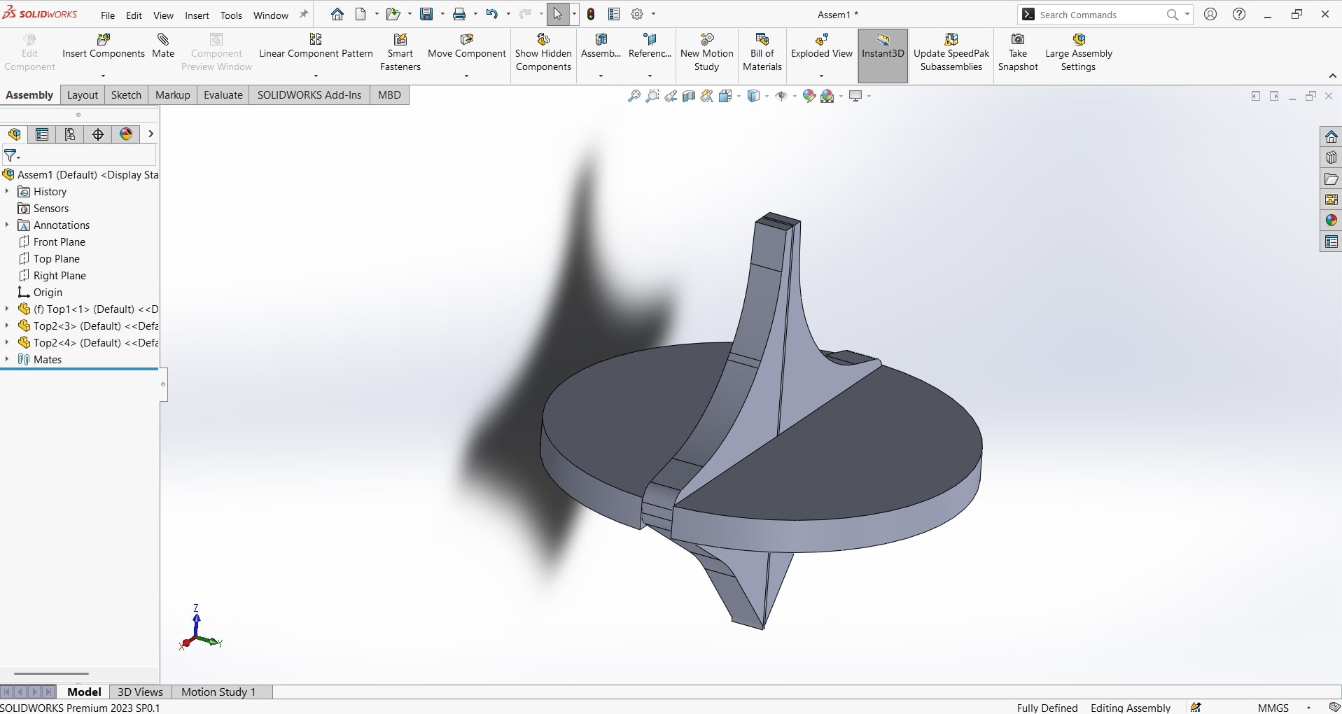
- Step 8: Test and Refine the Design
Modify parameter values to test the model's flexibility. Adjust the parameter table to update the geometry automatically and ensure that the design behaves as intended.
- Step 9: Save and Export
Save the parametric design in your software’s native file format. Export the design to formats like STL, STEP, or IGES for 3D printing, sharing, or manufacturing.
Parametric design streamlines the modeling process, making it easier to iterate and adapt designs. By following these steps, you can create flexible and scalable models that save time and enhance productivity.
2.How I Made my Press-Fit Construction Kit
How to Create a Press-Fit Construction Kit
A press-fit construction kit consists of interlocking components that fit together without glue or fasteners. This type of kit is ideal for prototyping, educational tools, and DIY projects. Below are the steps to design and create a press-fit construction kit:
- Step 1: Understand the Concept of Press-Fit
Press-fit assemblies rely on friction to hold parts together. The critical aspects include:
- Material: Use materials like cardboard, acrylic, or wood for laser cutting.
- Tolerance: Properly calculate the fit tolerance to ensure a snug but functional connection.
- Design: Components should have interlocking tabs and slots.
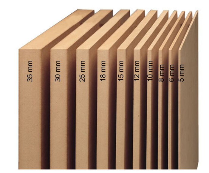
- Step 2: Choose the Materials
Select a material suitable for your project. Popular options include:
- Cardboard: Lightweight and easy to cut.
- Acrylic: Durable with a polished look.
- Wood: Offers strength and natural aesthetics.
- Step 3: Create a Parametric Design
Use CAD software like SolidWorks, Fusion 360, or Inkscape to design your kit:
- Set parameters for slot width, tab height, and part dimensions.
- Ensure slots match the material thickness for a proper fit.
- Incorporate equations to easily modify the design for different materials or scales.
- Step 4: Design Interlocking Components
Design parts with interlocking tabs and slots:
- Tabs: Extend from the edge of a part and fit into slots on another part.
- Slots: Create slots slightly narrower than the material thickness for a secure press-fit.
- Shapes: Include basic geometric parts (squares, triangles) and more complex shapes for versatility.
- Step 5: Test Fit Tolerances
Before finalizing the design, cut a few test pieces to check fit:
- Adjust slot dimensions based on material behavior (e.g., wood may require slightly larger slots due to rigidity).
- Ensure parts fit snugly but can be assembled and disassembled easily.
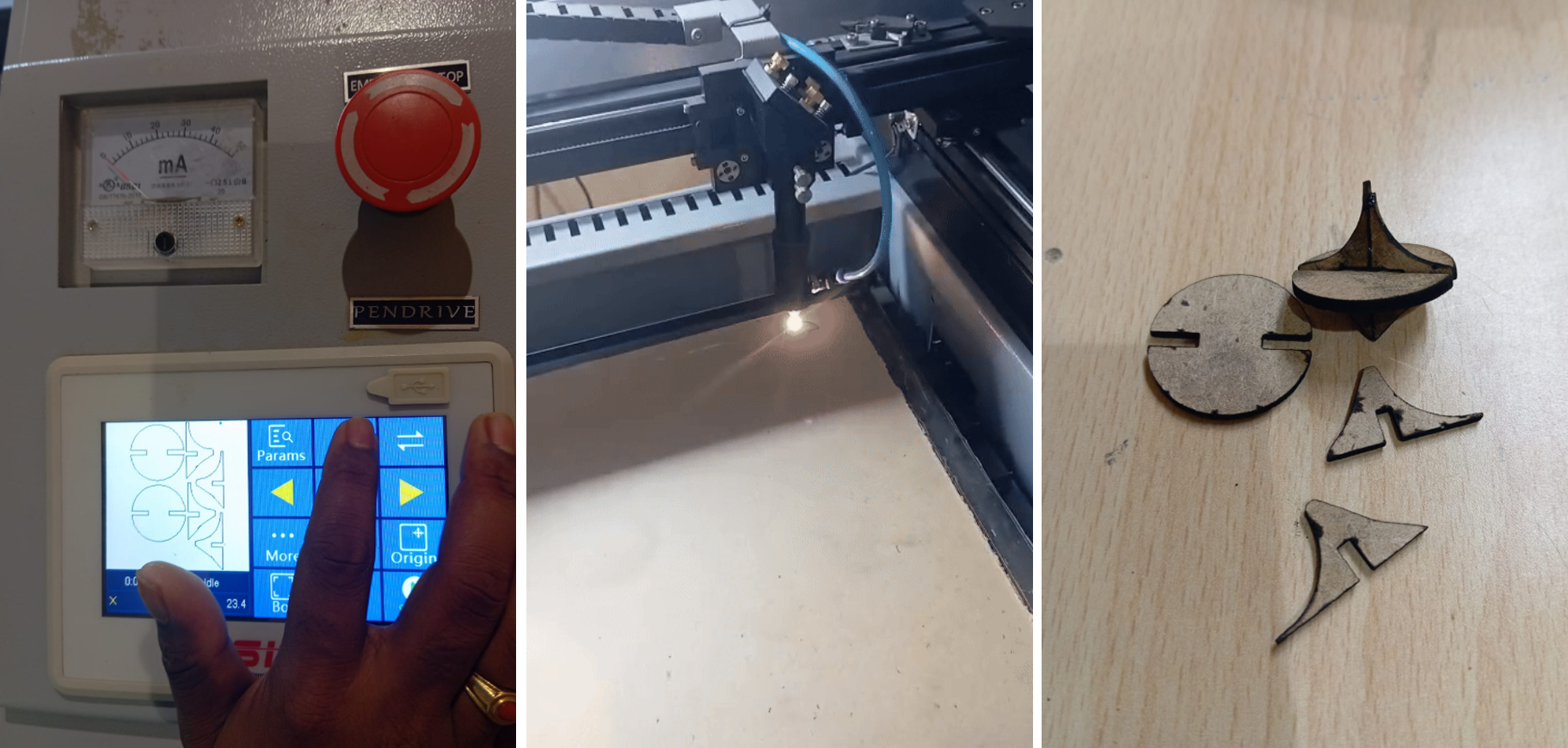
- Step 6: Cut the Components
Use a laser cutter or CNC machine to fabricate the parts:
- Import your design into the cutting software.
- Set material-specific parameters like cutting speed and power.
- Perform a test cut to confirm settings.
- Step 7: Assemble the Kit
Assemble the pieces to ensure all parts fit as designed. This step verifies the accuracy of your tolerances and provides an opportunity to make final adjustments.
- Step 8: Package and Distribute
Organize the components into a kit. Include instructions or diagrams for assembly. You can now use the kit for educational purposes, prototyping, or as a product.
By following these steps, you can create a functional and visually appealing press-fit construction kit. This process encourages creativity and hands-on learning while delivering a reusable and customizable product.
3. Documented How You Made Something with the Vinyl Cutter
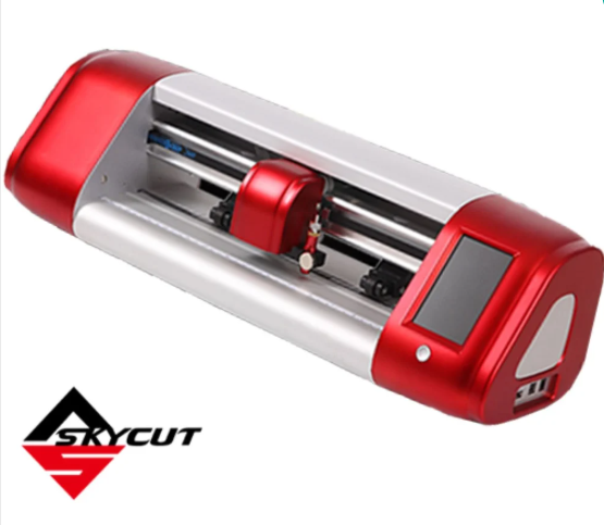
How to Cut with a Vinyl Cutter
A vinyl cutter is a versatile machine used to cut shapes, letters, and designs from sheets of vinyl. These machines are commonly used for creating stickers, decals, and signs. Below are the steps to cut with a vinyl cutter effectively:
- Step 1: Understand the Vinyl Cutter
Familiarize yourself with the basic components and functions:
- Blade: The cutting tool that precisely cuts the vinyl material.
- Cutting Mat: A sticky surface that holds the vinyl in place during cutting.
- Software: Used to design and send files to the cutter (e.g., Cricut Design Space, Silhouette Studio).
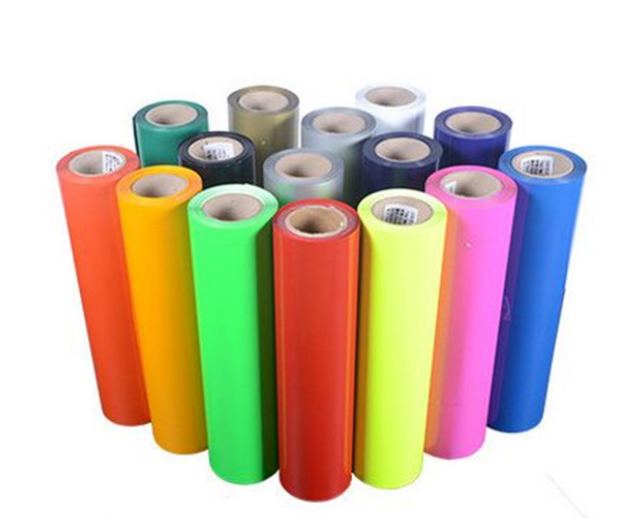
- Step 2: Choose the Vinyl Material
Select the type of vinyl appropriate for your project:
- Adhesive Vinyl: Used for decals, stickers, and labels.
- Heat Transfer Vinyl (HTV): Ideal for fabrics and garments.
- Specialty Vinyl: Includes glitter, holographic, or matte finishes for unique designs.
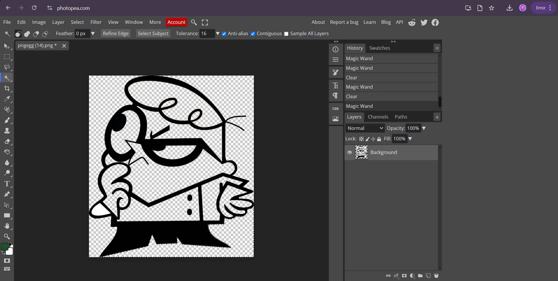
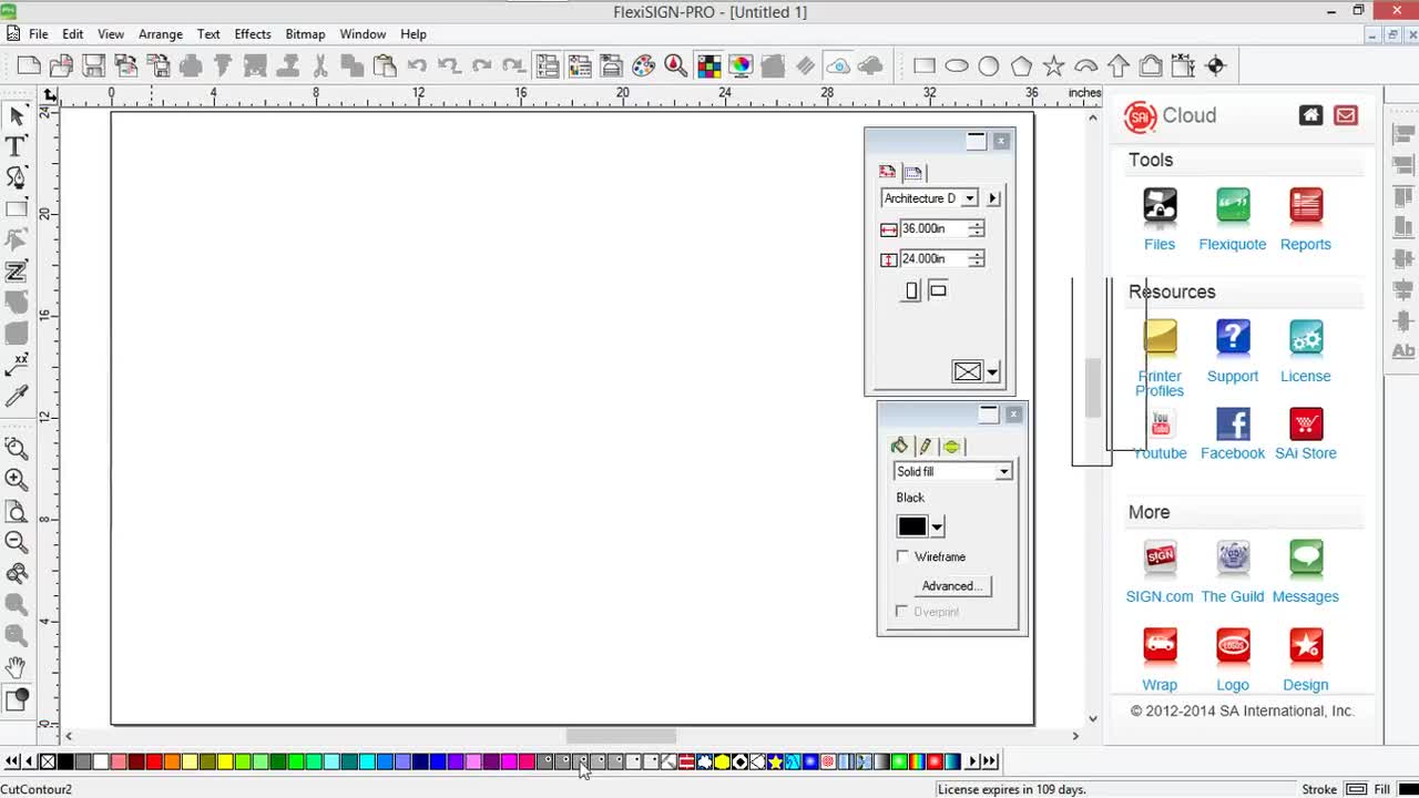
- Step 3: Create Your Design
Use design software to prepare your artwork:
- Choose shapes, text, or custom graphics.
- Ensure the design is in vector format for precise cutting.
- Adjust the size of the design to fit your vinyl sheet.
- Step 4: Load the Vinyl
Prepare the vinyl cutter for operation:
- Place the vinyl sheet or roll onto the cutting mat with the shiny side up (for adhesive vinyl) or matte side up (for HTV).
- Align the vinyl with the guide rollers on the cutter.
- Secure the vinyl to prevent shifting during cutting.
- Step 5: Adjust Cutting Settings
Configure the cutter for the material you are using:
- Set the blade depth according to the thickness of the vinyl.
- Adjust the speed and pressure settings in the software or cutter interface.
- Perform a test cut to ensure the settings are correct.
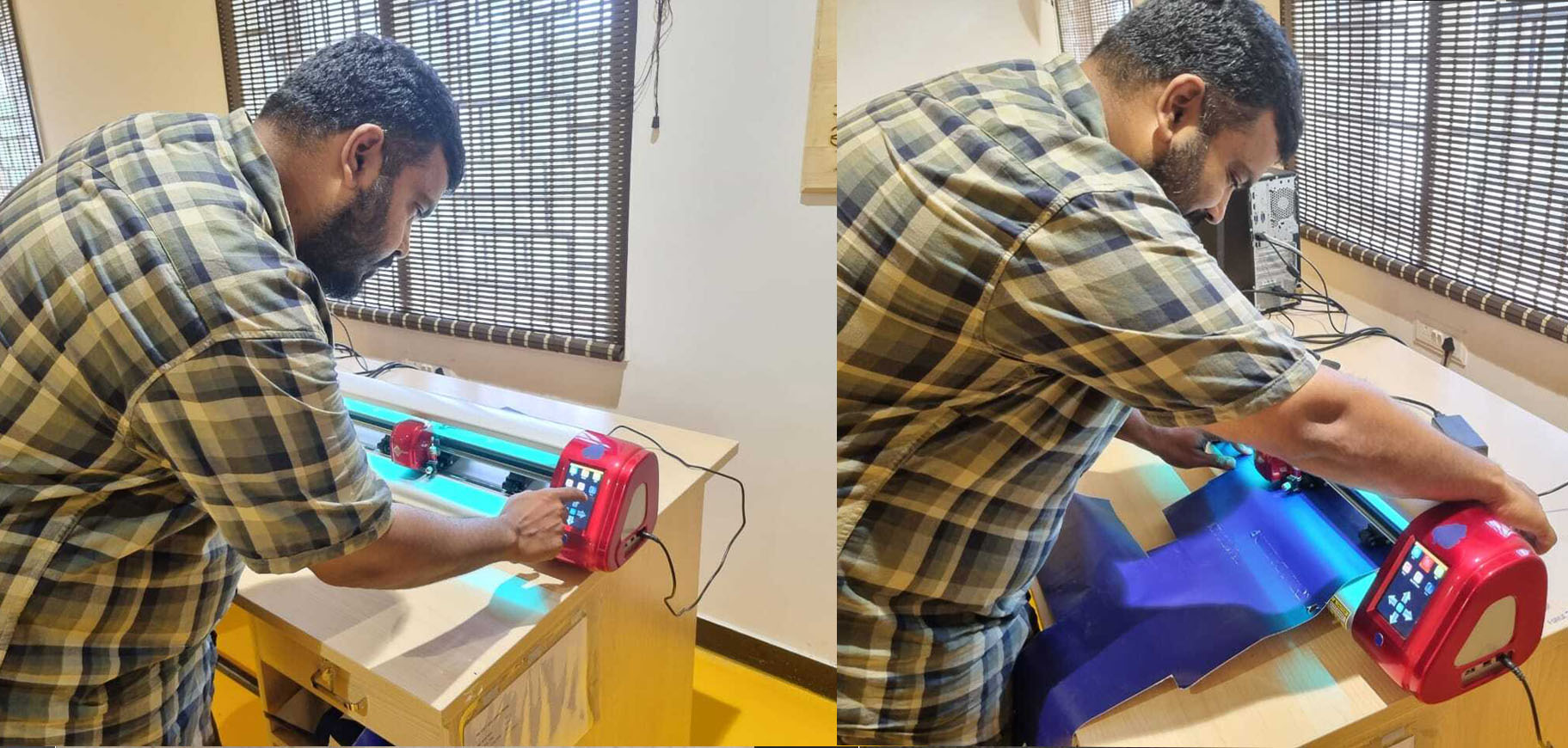
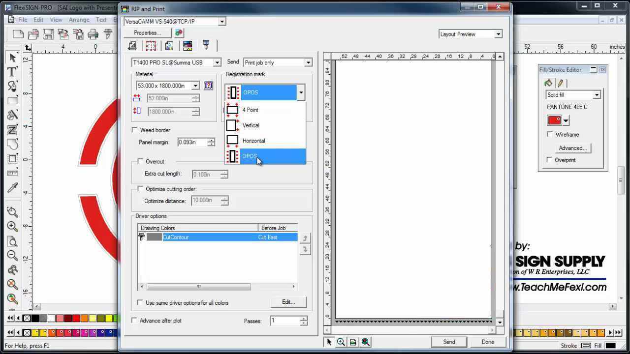
- Step 6: Send the Design to the Cutter
Upload your design file to the vinyl cutter:
- Use USB, Bluetooth, or a direct connection to communicate with the cutter.
- Preview the design placement on the vinyl to avoid wastage.
- Start the cutting process and monitor the cutter as it works.
- Step 7: Weed the Excess Vinyl
Remove the unwanted parts of the vinyl:
- Use a weeding tool to peel away the excess material around the design.
- Be careful not to lift the intended design elements.
- Step 8: Transfer the Design
Apply the cut vinyl to your desired surface:
- Use transfer tape to lift the design from the backing sheet.
- Position the design on the target surface and press firmly.
- Remove the transfer tape carefully, leaving the vinyl in place.
Following these steps ensures a smooth and efficient cutting process with a vinyl cutter. Whether for personal projects or professional applications, vinyl cutters enable precise and customizable creations.
4. Included Your Original Design Files
All original design files used in this assignment are included for reference:
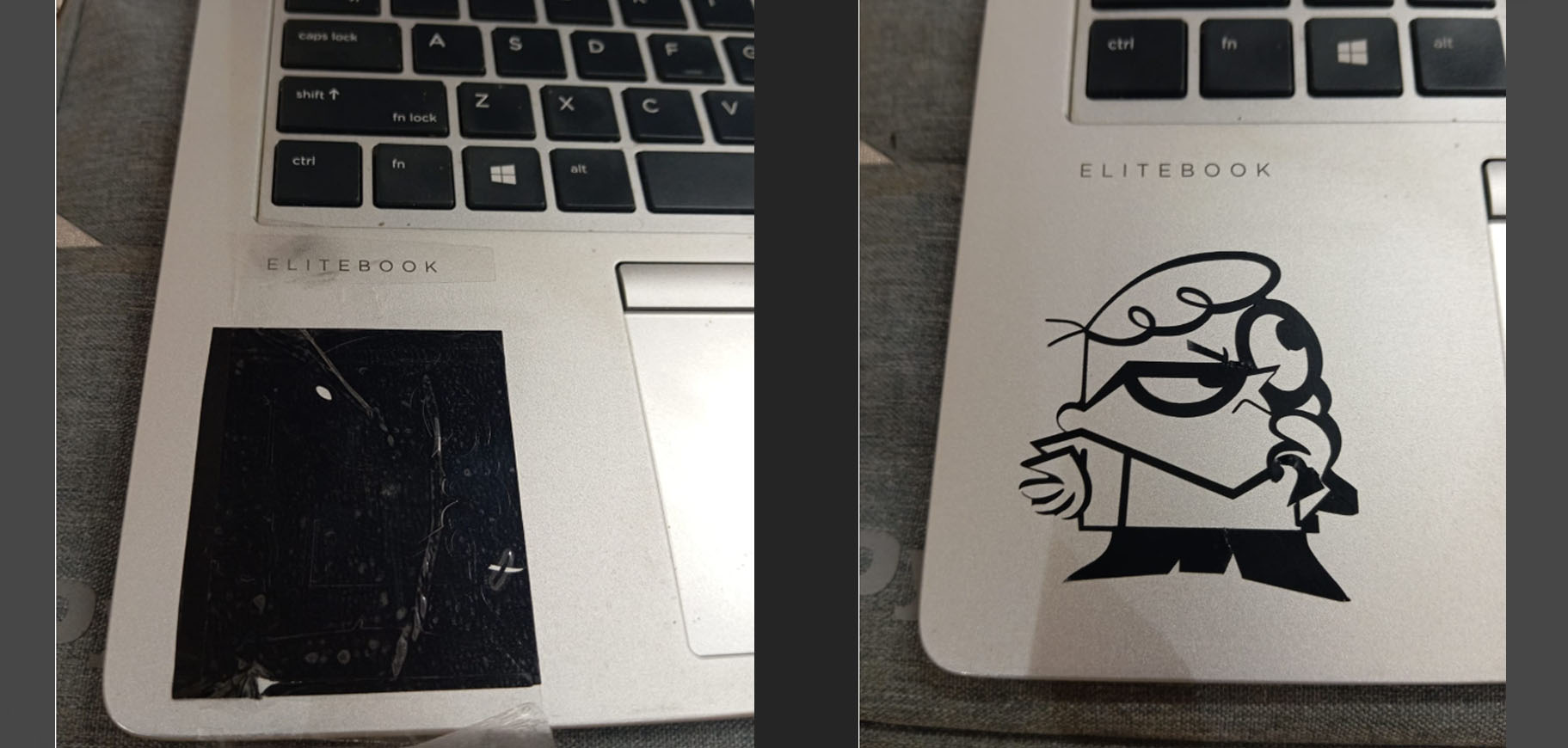
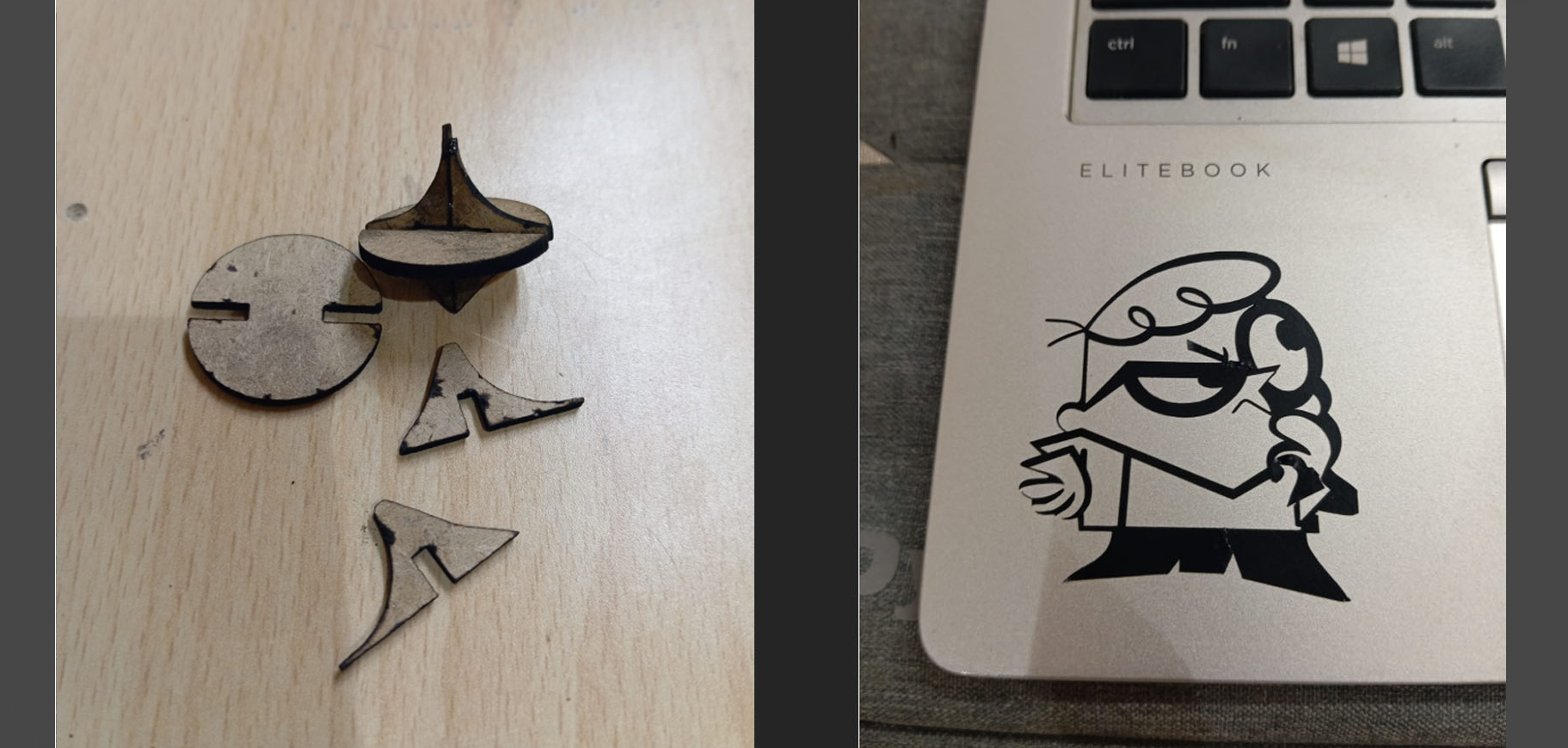
5. Included Hero Shots of Your Results
Here are the hero shots showcasing the final results of each task:
Conclusion
This assignment covered parametric design, press-fit construction, and vinyl cutting. By following systematic processes, I was able to create precise designs, fabricate components, and document the workflow effectively.