Week12: Mechanical Design, Machine Design
This project encompasses two phases: Mechanical Design and Machine Design. The Mechanical Design phase focuses on conceptualizing and building the mechanical parts of a machine with manual operation, while the Machine Design phase involves actuating, automating, and refining the design for practical applications. The tasks are divided into group and individual assignments, promoting teamwork and individual accountability.
My Contribution: Coding and Development
Link to Group Assignment (Group Assignment)
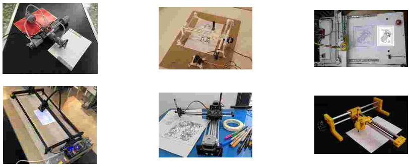
In this assignment, my primary focus was on the coding and development aspects. I utilized my skills to translate theoretical concepts and project requirements into functional, efficient, and well-structured code. A key highlight of my contribution was the creation of a 2D Plotter, which was developed from scratch and incorporated essential features for plotting and visualizing data effectively.

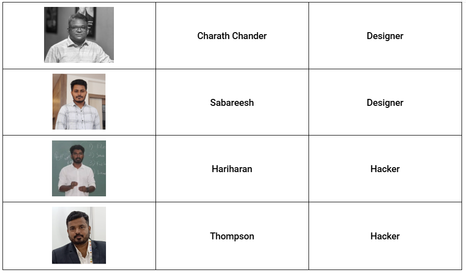
My Team
Understanding Requirements
Before beginning the development, I conducted a thorough analysis of the assignment’s objectives. The goal was to create a 2D plotter capable of graphically representing data in a user-friendly manner. I identified key functionalities such as support for multiple data input formats, the ability to customize plot styles, and ensuring smooth rendering of graphical elements.
Installing GRBL Firmware on the Arduino
The first step in setting up the 2D Plotter was to install the GRBL firmware on an Arduino Uno. This process enabled the Arduino to interpret G-code commands for controlling stepper motors and other hardware components. I used the Arduino IDE to accomplish this, and the steps were straightforward and efficient.
Flashing the GRBL Firmware
To flash the GRBL firmware onto the Arduino Uno, I followed these steps:
- Located the ‘grbl’ folder in the Arduino library folder.
- Loaded the GRBL library into the Arduino IDE by navigating to Sketch > Include Library > Add .ZIP Library and selecting the GRBL library.
- Once the GRBL library was successfully added, I opened the grblUpload sketch provided in the GRBL examples. This ensured the correct firmware was prepared for upload.
- Uploaded the firmware onto the Arduino Uno by selecting the appropriate board and port, then clicking on Upload in the Arduino IDE.
Using the Arduino IDE
The Arduino IDE played a critical role in this setup. It provided a user-friendly environment for adding the GRBL library and uploading the firmware. By opening the IDE, I ensured all necessary drivers and tools were pre-installed, allowing for seamless communication with the Arduino Uno. The GRBL firmware upload process was quick and efficient, enabling the hardware to be ready for G-code interpretation.
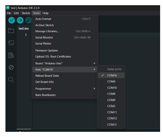
Setting Up the Communication Port and Hardware Connection
After completing the hardware assembly, the next crucial step is identifying the correct communication port (COM port) to which your microcontroller or board is connected. Ensuring this step is performed accurately is vital for successful interaction between your computer and the hardware.
Identifying and Connecting the Device
Begin by identifying the COM port associated with your microcontroller. Once located, securely connect your device to that port using the appropriate cable to establish a reliable connection. Proper connections are essential to avoid interruptions during data transfer.
Selecting the Board and Environment Setup
After confirming the connection, open your simulation or coding environment, such as Arduino IDE, TinkerCAD, or Wokwi. Navigate to the settings or tools menu, and select the correct board model that matches your hardware. Choosing the appropriate board ensures that the environment compiles the code correctly and allows for a seamless upload to the microcontroller.
Ensuring Smooth Communication
This step is critical for ensuring smooth communication and operation. By correctly configuring the communication port and selecting the appropriate board, you can minimize errors and achieve efficient interaction between your computer and the hardware. These precautions lay the foundation for a successful and error-free coding experience.
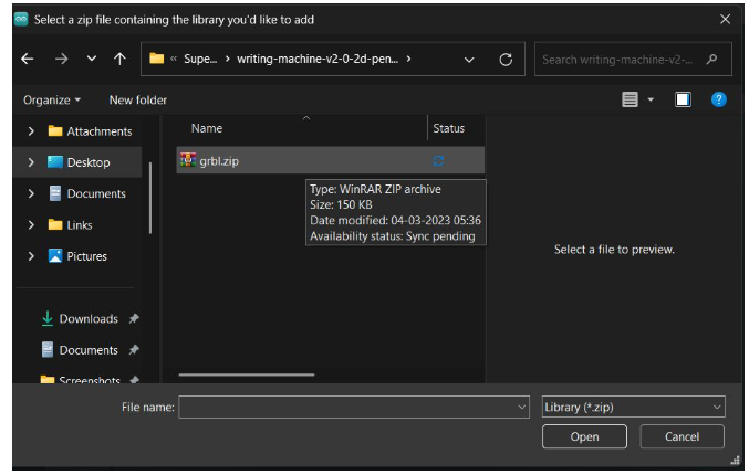
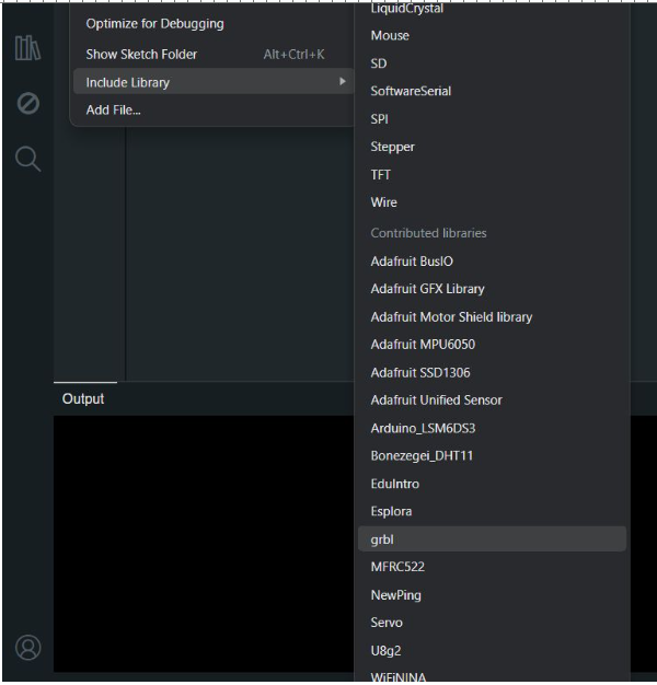
Adding a Custom Library in Arduino IDE
To incorporate a custom library into your project, navigate to Sketch → Include Library → Add .ZIP Library in the Arduino IDE. Select the ZIP file of the library you have downloaded. This action installs the library, making its functions readily available for use in your code.
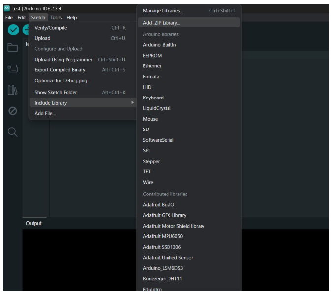
Selecting and Installing the Library
Locate the ZIP file on your system and click Open. The Arduino IDE will handle the installation automatically and add the library to the Contributed Libraries section for easy access.
Adding and Uploading the GRBL Library
To add the GRBL library, navigate to Sketch → Include Library → GRBL in the Arduino IDE. Once added, open the GRBL sketch and upload it to your board by clicking the Upload button in the IDE. This process ensures the GRBL firmware is correctly installed on your microcontroller.
Opening and Flashing the GRBL Firmware
Navigate to File → Examples → grbl → grblUpload in the Arduino IDE to open the GRBL uploader sketch. Once the sketch is loaded, click the Upload button to flash the GRBL firmware onto your board. This step prepares your microcontroller for G-code execution.
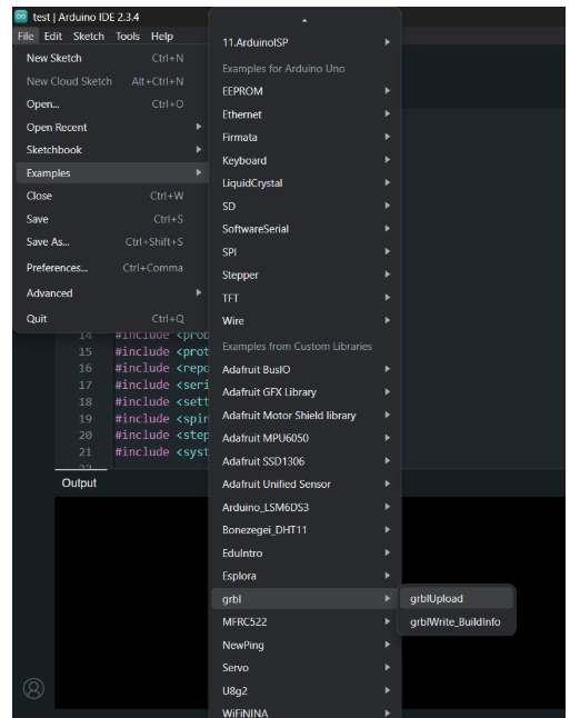
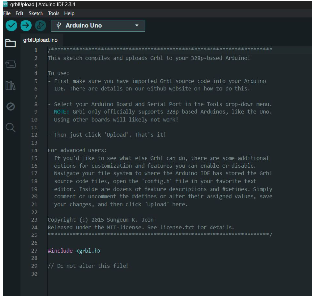
GRBL Firmware Loader
Upon selecting the GRBL uploader sketch, a new window will open containing the GRBL firmware loader. You can then use this sketch to upload the GRBL firmware to your board, completing the installation process.
Verifying the GRBL Upload Sketch
After opening the grblUpload sketch, click the Verify button in the Arduino IDE to ensure there are no errors in the code. This step helps identify potential issues before proceeding with the upload to your board.
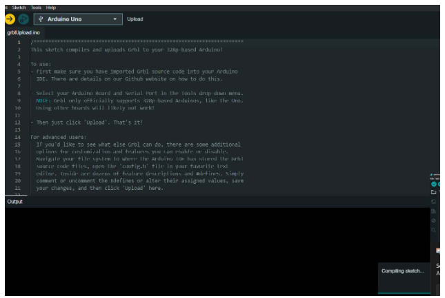
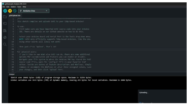
Uploading the GRBL Firmware
Once the grblUpload sketch has been successfully verified, click the Upload button in the Arduino IDE. This will upload the GRBL firmware to your board, completing the setup process.
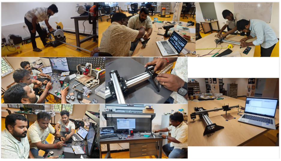
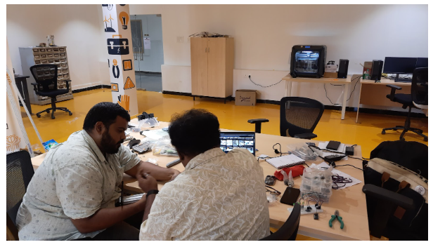
Wiring Up the Electronics
After successfully installing the firmware, the next critical task was setting up the wiring for the 2D plotters. This step involved integrating the stepper motors, driver modules, and additional components with the Arduino to ensure smooth and accurate operations.
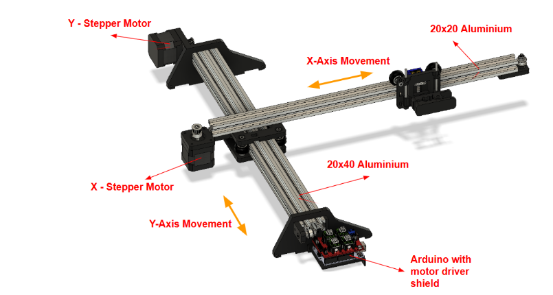
Stepper Motors and Driver Modules
The stepper motors were connected using A4988 driver modules. These drivers facilitated precise control over motor movements, which is crucial for both plotting and engraving tasks. Each driver was configured with the correct wiring to the Arduino, ensuring compatibility and efficient performance.
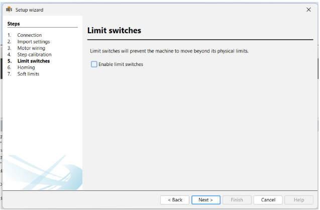
Limit Switches
Limit switches were installed to define movement boundaries, preventing the motors from overextending. These switches were connected to designated pins on the Arduino and calibrated to accurately restrict the axes' motion within the defined workspace.
Power Supply
A 12V power supply was used to power the setup. This power source provided sufficient energy for both plotters to operate reliably. Care was taken to ensure proper voltage regulation to protect the electronic components.
Custom Wiring for Plotter Types
The wiring was tailored to suit the specific requirements of each plotter:
- Pen Plotter: The wiring was optimized for precise movements to enable accurate drawing and writing tasks. Special attention was given to the pen-lifting mechanism to ensure seamless operations.
- Light Engraving Plotter: Connections were adjusted to accommodate the additional power requirements and controls for the engraving tool. This setup enabled smooth and consistent light engraving on various materials.
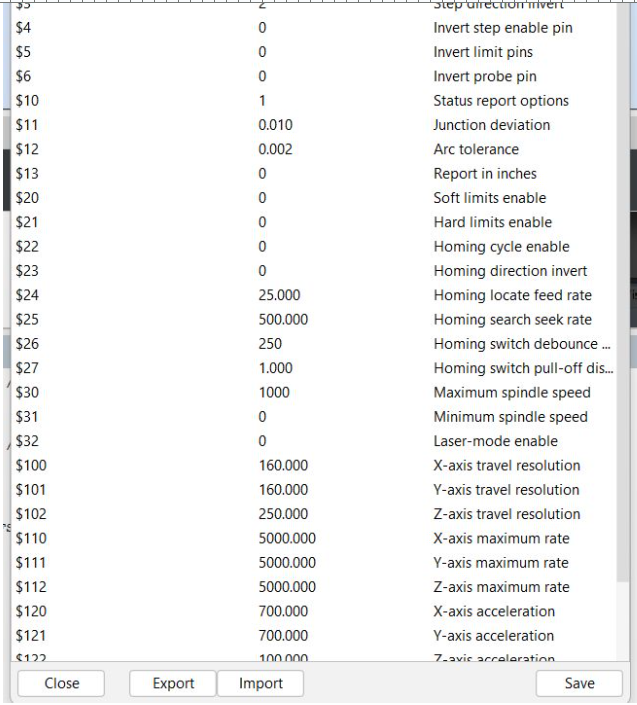
Configuring the UGS Settings
After completing the wiring, the next step was to configure the GRBL settings for optimal performance. By typing $ in the command interface, we accessed the default GRBL parameters to review and adjust them as needed.
Key GRBL Parameters Updated
$100, $101, $102– Set the steps per millimeter for the X, Y, and Z axes to ensure precise movement.$3– Adjusted the axis direction in case any axis was moving incorrectly.$120, $121, $122– Configured acceleration values for smooth and controlled motor operation.$30– Set the maximum spindle speed, particularly important for the engraving setup.
These values were carefully tuned for each plotter according to their specific motion and speed requirements to achieve accurate and efficient performance.
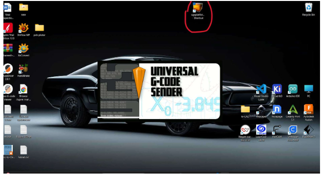
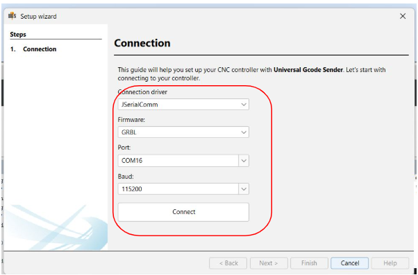
Launching Universal Gcode Sender (UGS)
To control and communicate with the CNC machine or GRBL-based hardware, we launched the Universal Gcode Sender (UGS) software on the laptop. UGS served as the interface for sending commands, monitoring machine status, and managing the plotting or engraving tasks seamlessly.
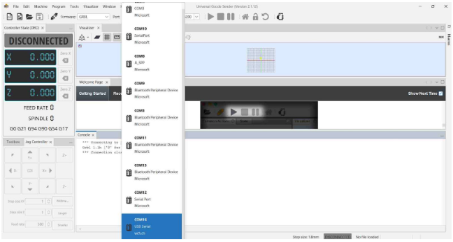
Selecting the Correct Port
Within the Universal Gcode Sender (UGS) software, select the correct communication port that corresponds to your CNC controller (for example, an Arduino running GRBL firmware). Choosing the proper port is essential for establishing a reliable connection between your computer and the hardware.
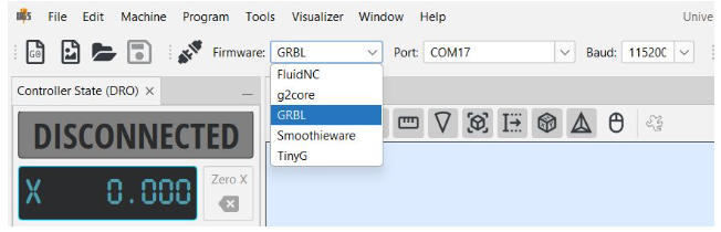
Identifying the Correct COM Port in UGS
At the top of the Universal Gcode Sender (UGS) interface, locate the connection panel and find the dropdown menu labeled "Port" or "COM Port".
Click the dropdown to view all available serial ports. If you are unsure which port corresponds to your CNC device, follow these steps:
- Unplug the USB cable from your device and observe the list of ports.
- Plug the USB cable back in and check which new port appears in the dropdown menu.
The newly listed port (such as COM3, COM4, or /dev/ttyUSB0) is your device’s communication port.
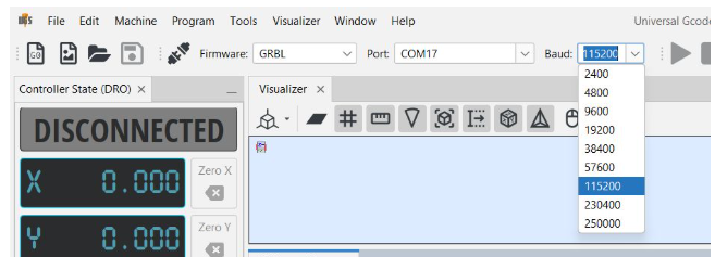
Selecting the Baud Rate
After selecting the correct communication port in the Universal Gcode Sender (UGS), choose the appropriate baud rate for the connection. For GRBL firmware, the typical baud rate is 115200. Setting this correctly ensures smooth and reliable communication between your computer and the CNC controller.
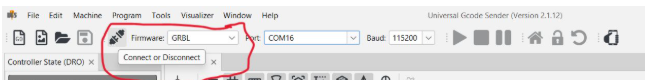
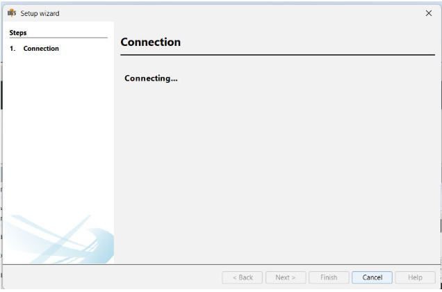
Establishing Connection
Once you have selected the correct port and set the baud rate to 115200, click on the "Connect" button in the Universal Gcode Sender (UGS) interface. This will establish communication between your computer and the CNC device, allowing you to control and monitor the machine.
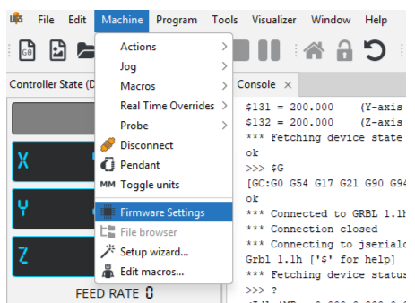
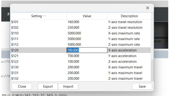
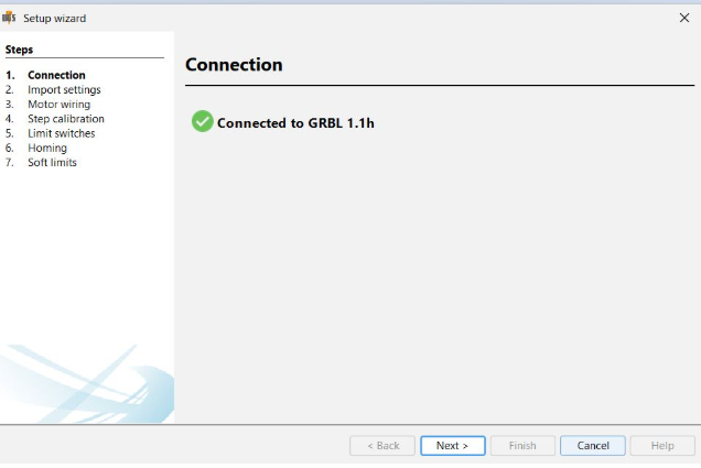
Accessing and Configuring Firmware Settings
After successfully connecting to your CNC device, you will be able to view the machine’s current status and start sending commands or G-code for execution.
The next step is to configure your machine using the Firmware Settings in UGS:
- Go to the top menu bar and click on "Machine".
- From the dropdown menu, select "Firmware Settings".
- The Firmware Settings wizard will launch, guiding you through several important configuration steps to optimize your machine’s performance.
Optimizing Firmware Settings
We carefully reviewed the firmware description and, using that information, adjusted the configuration values accordingly. The optimization process took some time, as it involved fine-tuning to achieve the best possible performance. Through iterative adjustments, we managed to set values that were as close as possible to the ideal settings for our specific machine setup.
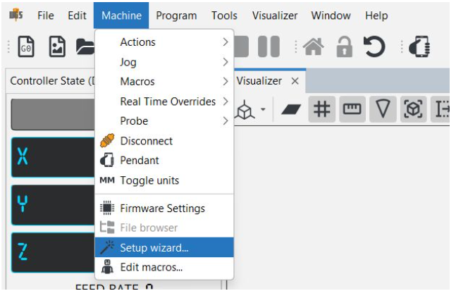
Using the UGS Setup Wizard
To begin configuring your machine, open the Setup Wizard in Universal Gcode Sender (UGS):
- Click on "Machine" in the top menu bar.
- Select "Setup Wizard" from the dropdown menu.
- The wizard will launch and guide you step-by-step through the necessary configuration processes to prepare your machine for operation.
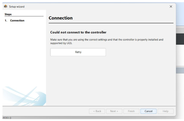
Setup Wizard Interruption and Recovery
During the setup wizard process, we accidentally unplugged the USB cable, which caused the connection to be lost and interrupted the configuration. We then reconnected the device and resumed the setup from where it left off, ensuring the process was completed successfully despite the temporary disruption.
Successful Connection After Configuration
After completing the setup and configuration steps, the device connected properly without any issues. This confirmed that the settings were correctly applied and the machine was ready for reliable operation.
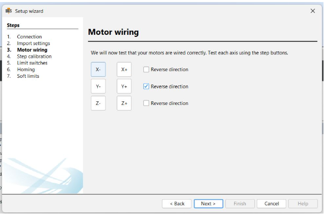
Motor Connection and Direction Configuration in Setup Wizard
In the setup wizard, begin by ensuring that the X and Y motors are correctly connected to their designated ports on the control board. Verify that all cables are securely plugged in with no loose connections.
If the motors were previously unplugged, make sure the machine is powered off before reconnecting them. After securely reconnecting, power the machine back on and continue to the motor configuration section within the setup wizard.
During this configuration step, observe the direction of motor movements. If the Y-axis motor moves in the opposite direction, the wizard provides an option to reverse the motor direction. Simply select the option to invert the Y-axis motor.
After adjusting the direction, perform a quick test from the wizard to confirm the motors are moving correctly. Reversing the Y-axis motor direction when necessary is essential for proper movement, alignment, and smooth operation of the plotter.
Step Calibration in Setup Wizard
After completing the motor wiring and direction configuration, proceed to the step calibration section in the setup wizard. This step is crucial to ensure that your machine moves the precise distance corresponding to the commands it receives, enabling accurate plotting or engraving operations.
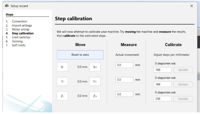
Calibrating Movement for an Axis
Start the calibration by selecting one axis, usually the X or Y axis. Use a precise measuring tool, such as a ruler or caliper, to mark a clear reference point on your machine’s gantry or base.
Next, command the machine to move a specific distance—for example, 1mm. Once the movement is complete, measure the actual distance traveled from your original reference point.
If the actual distance differs from the commanded distance, you will need to adjust the steps-per-millimeter value for that axis to correct the discrepancy and improve movement accuracy.
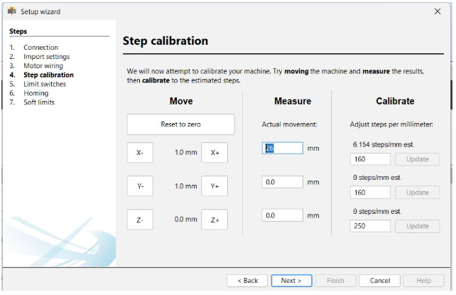
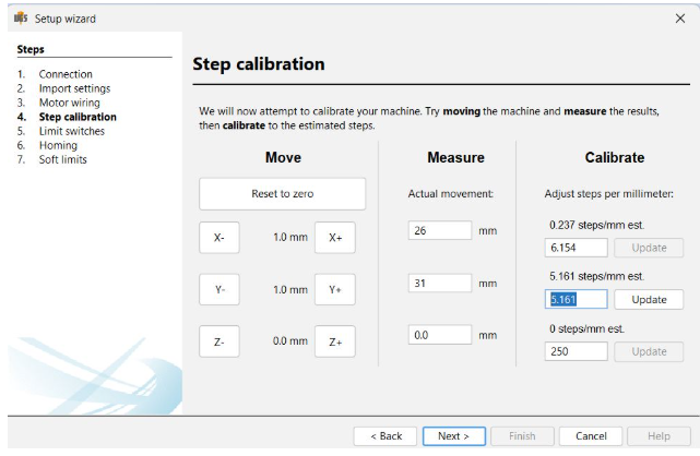
Automatic Steps-Per-MM Adjustment
Within the setup wizard, you will find an option to enter the actual distance the machine traveled during the test move. After entering this value, the software will automatically calculate and update the correct steps-per-millimeter setting for the selected axis, ensuring precise and accurate movement.
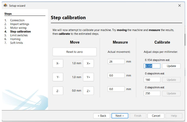
Repeating Calibration for Both Axes
Repeat the calibration process for both the X and Y axes to guarantee precise and accurate movement in all directions. This step is critical because even minor errors in steps-per-millimeter can significantly impact the final output or print quality, especially in CNC applications where precision is paramount.
Challenges Faced During Configuration
During the setup of the plotters, we encountered several challenges, particularly in the early testing phases using Universal G-code Sender (UGCS). One significant issue was unexpected and excessive movement. For instance, when we commanded the X-axis to move a small distance such as 1 mm, the plotter often moved much further, sometimes jumping several millimeters beyond the intended position. This behavior indicated a problem in our configuration settings.
After investigating, we discovered that the root cause was the high acceleration and feed rate values set in the GRBL firmware. These settings were too aggressive for our mechanical setup. The stepper motors were unable to keep pace with the rapid commands, leading to overshooting and unstable, jittery motion.
During initial testing, we also observed significant vibration, especially when the motors attempted to accelerate quickly. Following our instructor’s advice, we reduced the acceleration parameters, which resulted in a noticeable improvement— the machine began operating much more smoothly.
To resolve the remaining issues, we adopted a systematic tuning approach:
- Gradually decreased the acceleration values ($120, $121, $122) to more manageable levels.
- Lowered the feed rate to match the machine’s mechanical capabilities.
- Performed repeated testing after each adjustment, using UGCS to monitor machine response closely.
We also faced a power supply challenge early in the project. Initially, we used a 12V 2A power supply, assuming it would suffice. However, the motors were weak and sluggish, especially when multiple axes moved simultaneously. We later realized that the stepper motors were wired in series, which increased the electrical load. To fix this, we upgraded to an 18V 3–4A power supply, significantly stabilizing the system.
Even after addressing the power supply, minor movement glitches persisted. These were resolved through careful and incremental parameter tuning. Although the process required patience and multiple iterations, it ultimately resulted in both plotters achieving accurate, smooth, and consistent performance.
Conclusion: Coding Aspect of the 2D Plotter
The coding phase of the 2D plotter project was a crucial step that transformed conceptual ideas into a functional and efficient machine. By carefully writing and configuring the GRBL firmware, integrating it with the Arduino, and tuning the movement parameters, we ensured precise control over the stepper motors and accurate plotting operations. The development process involved iterative testing, debugging, and optimization to handle challenges such as motor direction, acceleration, and power management. Overall, the coding efforts provided a reliable foundation for the hardware to perform smoothly, enabling the 2D plotter to achieve consistent and accurate results.