Week 12: Mechanical & Machine Design
The Group assignment for this week is to build a machine and document the project and individual contribution
Our Group
Charath Chander | Designer | |
Sabareesh | Designer | |
Hariharan | Hacker | |
Thompson | Hacker |
Individual Contribution:
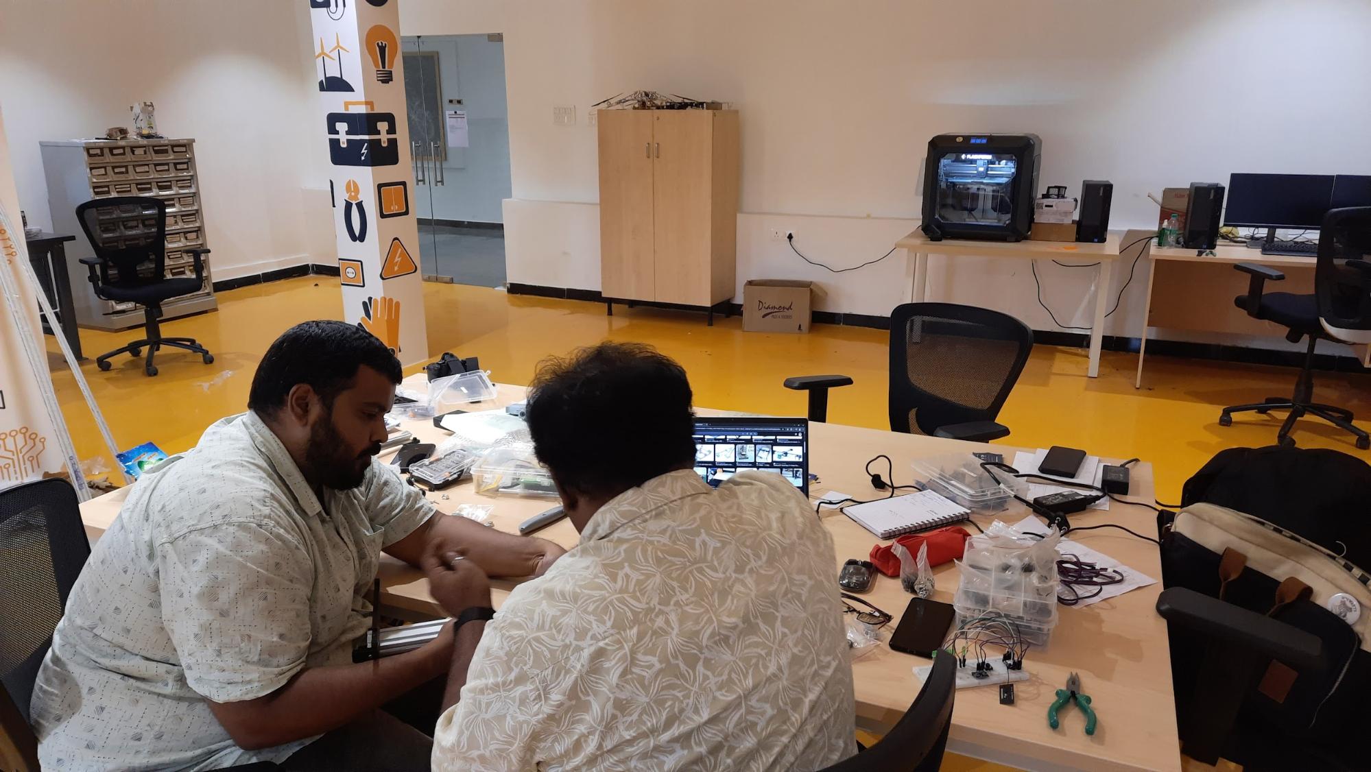
I have contributed to fabrication, assembly, and documentation. This week was interesting because people came together as a team to build a machine. Since I am skilled in mechanical tools and fabrication, I contributed to the fabrication of parts and assembling them together.
Concept Generation: PCB Prototyping
When moving from PCB milling to traditional etching, you'll find different challenges and trade-offs. While milling can be complex due to G-code generation, accuracy, bed flatness, tool selection, and depth control, etching introduces its own considerations. Instead of directly generating G-code, you'll be focusing on creating a robust resist pattern using an XY plotter and a permanent marker. Factors like the marker's ink consistency, the plotter's precision in tracing, and the cleanliness of the copper board will become critical for achieving well-defined tracks and footprints. Additionally, the etching process itself, involving chemical solutions and timing, will require careful control to avoid over- or under-etching.
Choice of mechanism:
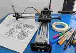
At its core, a DIY pen plotter is a homemade machine designed to move a pen or other drawing tool across a surface (usually paper) to recreate digital artwork or text. Unlike inkjet or laser printers that deposit ink or toner, pen plotters physically draw lines using a variety of writing and drawing implements.
Key Components of a Typical DIY Pen Plotter:
DIY Pen plotters are available on Instructables
Instructables is a fantastic resource for DIY projects, and there are many pen plotter designs and tutorials available. Here are a few examples of DIY pen plotter projects you can find on Instructables:
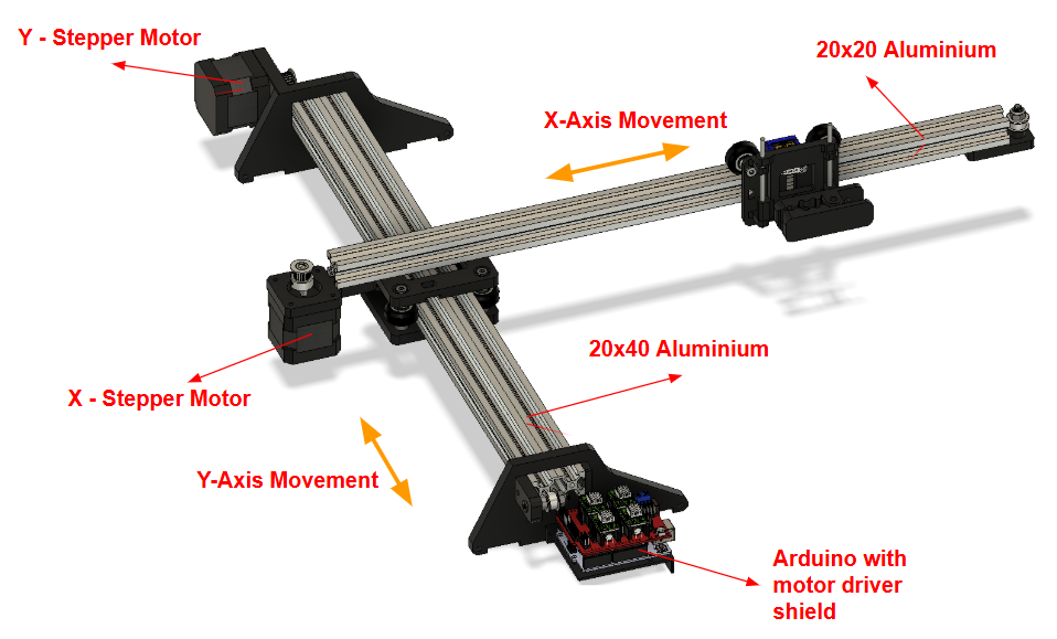
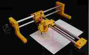
Our concept inspiration:
We have been inspired by the concept of using the aluminium extrusion model developed by Superb Tech. The design is clean and a very simple mechanism that will be very much suitable for the purpose.
Basic Parts of the Plotter from Superb Tech:
YouTube: video link
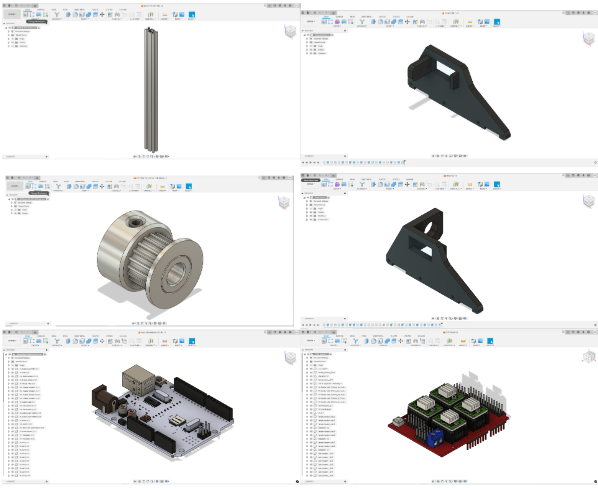
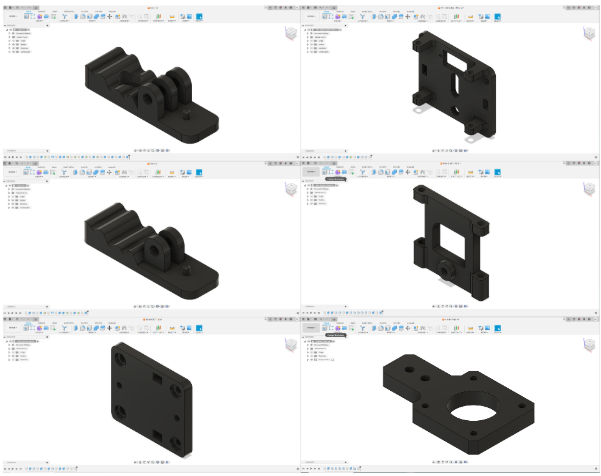
CAD design
For CAD design, we are using Fusion 360 to recreate the parts for the machine
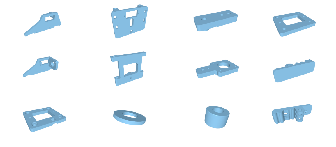
3D printing of Parts
A total of 12 parts 3D printed using an FDM printer. Details of the files, print duration, weight, and cost are listed in this table given below.
3D PRINTED PARTS LIST | ||||||||
# | FILE LINK | FILE NAME | QUANTITY | DENSITY | TIME TAKEN PER UNIT | WEIGHT(GRAMS) PER UNIT | COST (RS) PER UNIT | TOTAL COST (RS) |
1 | X pulley plate | 1 | 50% | 54 mins | ₹8.52 | ₹102.24 | ₹102.24 | |
2 | X motor plate | 1 | 50% | 1 hour 45 mins | ₹16.76 | ₹201.12 | ₹201.12 | |
3 | Pen Holder Z Plate | 1 | 50% | 1 hour 43 mins | ₹15.37 | ₹184.44 | ₹184.44 | |
4 | Pen Holder Base Plate | 1 | 50% | 2 hours 17 mins | ₹20.08 | ₹240.96 | ₹240.96 | |
5 | Intersection Bottom | 1 | 50% | 3 hours 9 mins | ₹32.41 | ₹388.92 | ₹388.92 | |
6 | Intersection Top | 1 | 50% | 3 hours 15 mins | ₹31.99 | ₹383.88 | ₹383.88 | |
7 | Clip 2 | 1 | 50% | 1 hour 18 mins | ₹10.90 | ₹130.80 | ₹130.80 | |
8 | Clip 1 | 1 | 50% | 1 hours 28 mins | ₹11.30 | ₹135.60 | ₹135.60 | |
9 | Base Plate Top | 1 | 50% | 7 hours 24 mins | ₹69.64 | ₹835.68 | ₹835.68 | |
10 | Base Plate Bottom | 1 | 50% | 5 hours 57 mins | ₹58.19 | ₹698.28 | ₹698.28 | |
11 | Arduino Plate | 1 | 50% | 1 hour 46 mins | ₹20.61 | ₹247.32 | ₹247.32 | |
12 | Shim Washer | 13 | 100% | 2 mins | ₹0.44 | ₹5.28 | ₹68.64 | |
13 | Spacer ( 6mm) | 12 | 100% | 6 mins | ₹0.81 | ₹9.72 | ₹116.64 | |
Total | 12 | ₹297.02 | ₹3,564.24 | ₹3,734.52 | ||||
List of inventory required for building the plotter
2D PLOTTER Inventory | |||||||
# | NAME | DESCRIPTION | RATE PER UNIT | QTY | COST | LINK(AMAZON) | LINK(ROBU) |
1 | 2020 V SLOT ALUMINIUM EXTRUSION PROFILE | 400MM (upto 500MM OPTIONAL) | ₹440 | 1 | ₹440 | ||
2 | 2040 V SLOT ALUMINIUM EXTRUSION PROFILE | 400MM (upto 500MM OPTIONAL) | ₹495 | 1 | ₹495 | ||
3 | RUBBER FEET SET 4PCS | 4 | ₹0 | ||||
4 | DELRIN V WHEEL KIT | 5MM BORE | ₹150 | 7 | ₹1,050 | ||
5 | ECCENTRIC SPACERS | 10 HEX 6MM WIDTH | ₹80 | 12 | ₹960 | ||
6 | GT2 BELT | 2 METERS (3M FOR LARGER FRAME) | ₹194 | 1 | ₹194 | ||
7 | GT2 PULLEY | 20 TEETH 5MM BORE | ₹25 | 2 | ₹50 | ||
8 | IDLER PULLEY | 5MM BORE | ₹380 | 2 | ₹760 | ||
9 | 3MM SHAFT STAINLESS STEEL | 80MM LENGTH EACH | - | - | ₹1,369 | ||
10 | 3MM SPRINGS | BALL PEN SPRING CAN BE USED | - | - | ₹0 | ||
11 | 3D PRINTER SPRING | FOR PEN HOLDER CLIP | - | - | ₹199 | ||
TOTAL COST | ₹5,517 | ||||||
Links from Indian purchase link attached
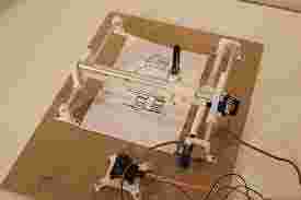
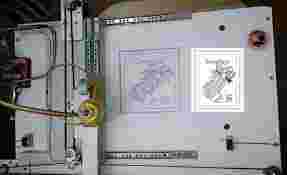
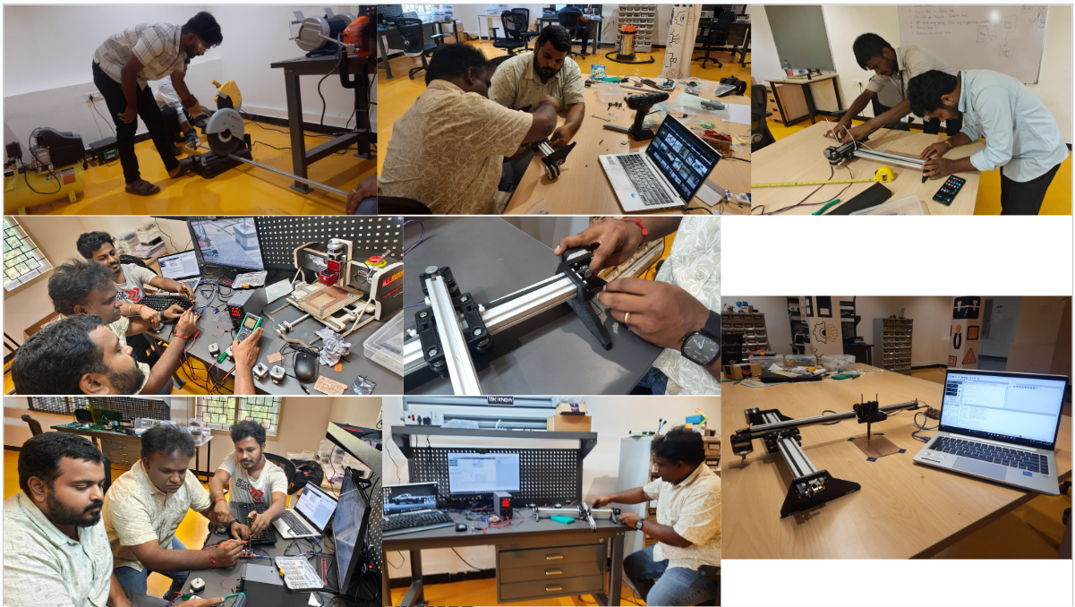
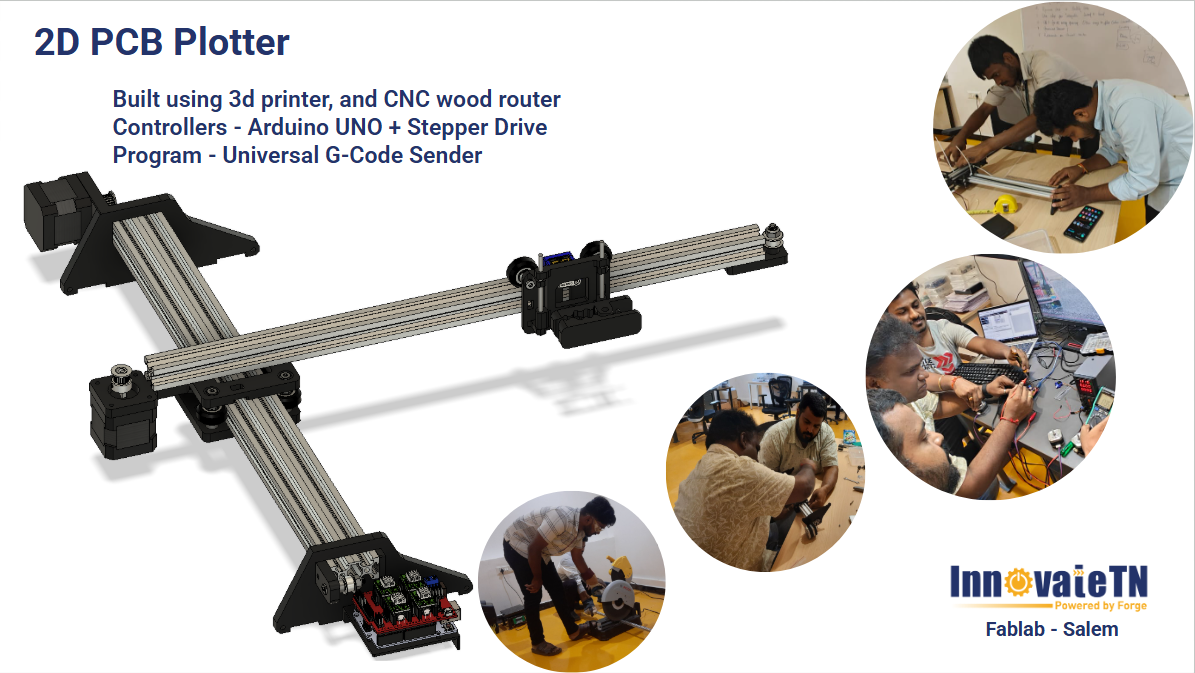
Machine Build:
Interface Software:
Download link for Grbl: Link
Download link for GCode sender: Link
Youtube learning links: Link
To install GRBL | |
Universal G-Code Sender |
What is GBRL ?
GRBL and Arduino boards, specifically ATmega328-based systems, go hand in hand, providing seamless integration for your CNC projects. GRBL interprets G-codes and communicates the necessary signals to Arduino, which subsequently manages the stepper motors of the CNC machine.
This close relationship between GRBL and Arduino ensures precise and efficient control of your CNC machine, ultimately giving life to your creative designs.
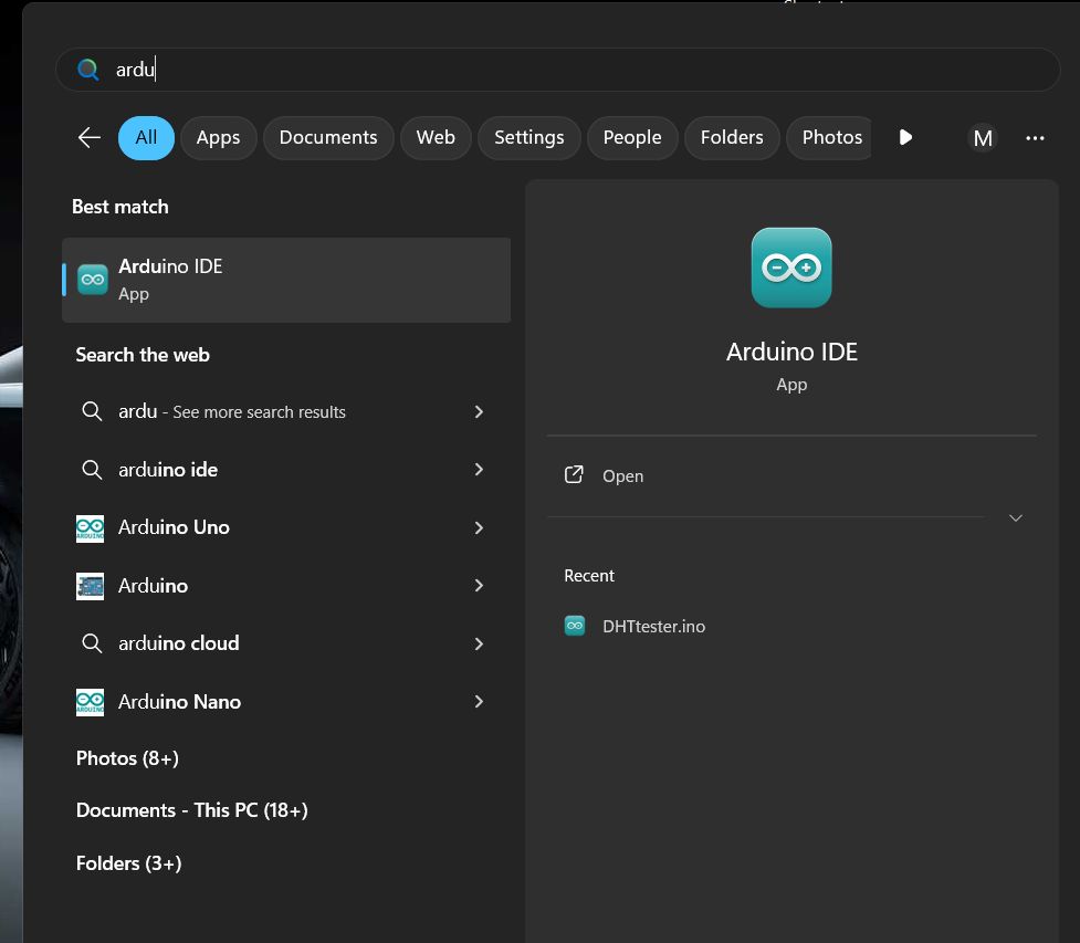
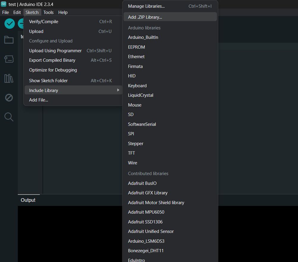
First things first, we flashed the GRBL firmware onto an Arduino Uno. I used the Arduino IDE for this. It was pretty straightforward—Locate the ‘grbl’ folder in the Arduino library folder and navigate to ‘Sketch > Include Library > Add.ZIP Library’ in the Arduino IDE to load the GRBL library.
In Arduino IDE we upload GRBL file
First open the Arduino IDE
Once your hardware setup is ready, the next important step is to identify the correct communication port (COM port) to which your microcontroller or board is connected.
After identifying it, ensure that you connect your device properly to that port using the appropriate cable.
Once the connection is established, open your simulation or coding environment (like Arduino IDE, TinkerCAD, or Wokwi), and select the correct board model from the tools or settings menu.
Choosing the right board ensures proper compilation and successful uploading of your code to the hardware.This step is critical for smooth operation and communication between your laptop and the microcontroller.
To add a custom library, go to Sketch → Include Library → Add .ZIP Library in the Arduino IDE and select your downloaded ZIP file.
This installs the library, allowing you to use its functions in your code.
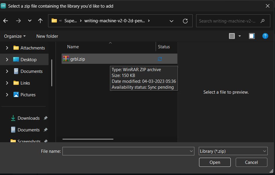
Choose the ZIP file from your system and click Open; the Arduino IDE will automatically install it and list it under Contributed Libraries.
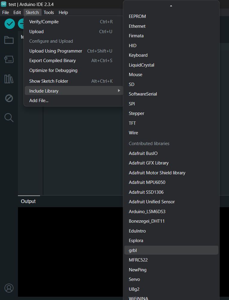
Go to Sketch → Include Library → GRBL to add it, then upload the GRBL sketch to your board using the Upload button in the Arduino IDE.
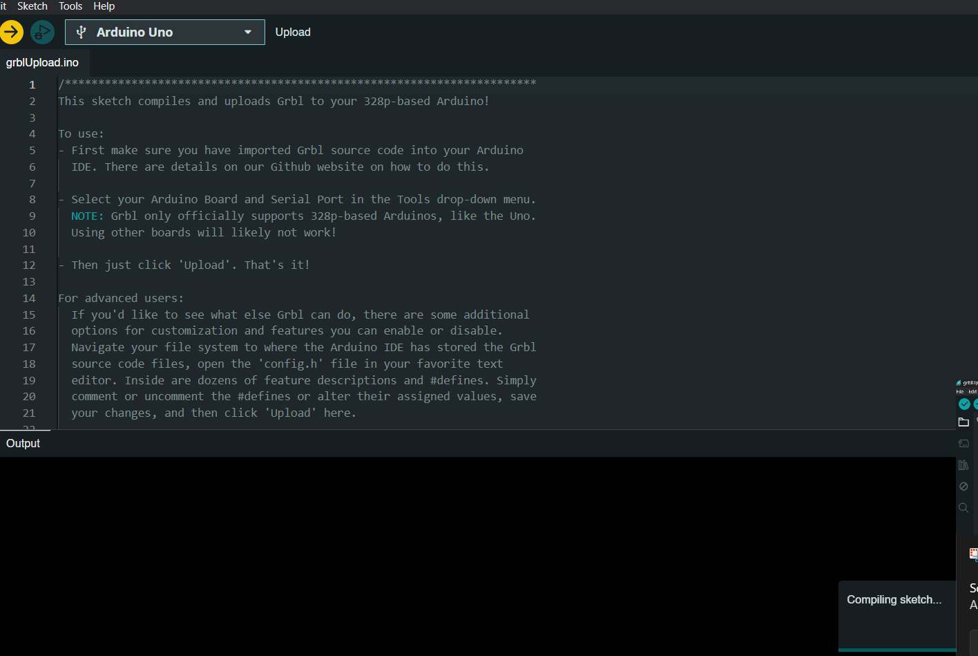
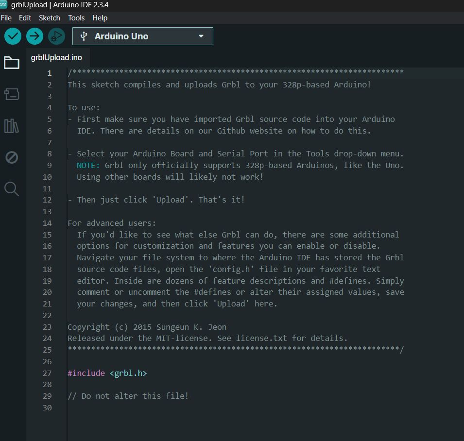
Go to File → Examples → grbl → grblUpload to open the GRBL uploader sketch. Then, click Upload to flash GRBL firmware to your board.
a sketch will open containing the GRBL firmware loader, which you can then upload to your board.
After opening the grblUpload sketch, click the Verify button in the Arduino IDE to check for any errors before uploading the code to your board.
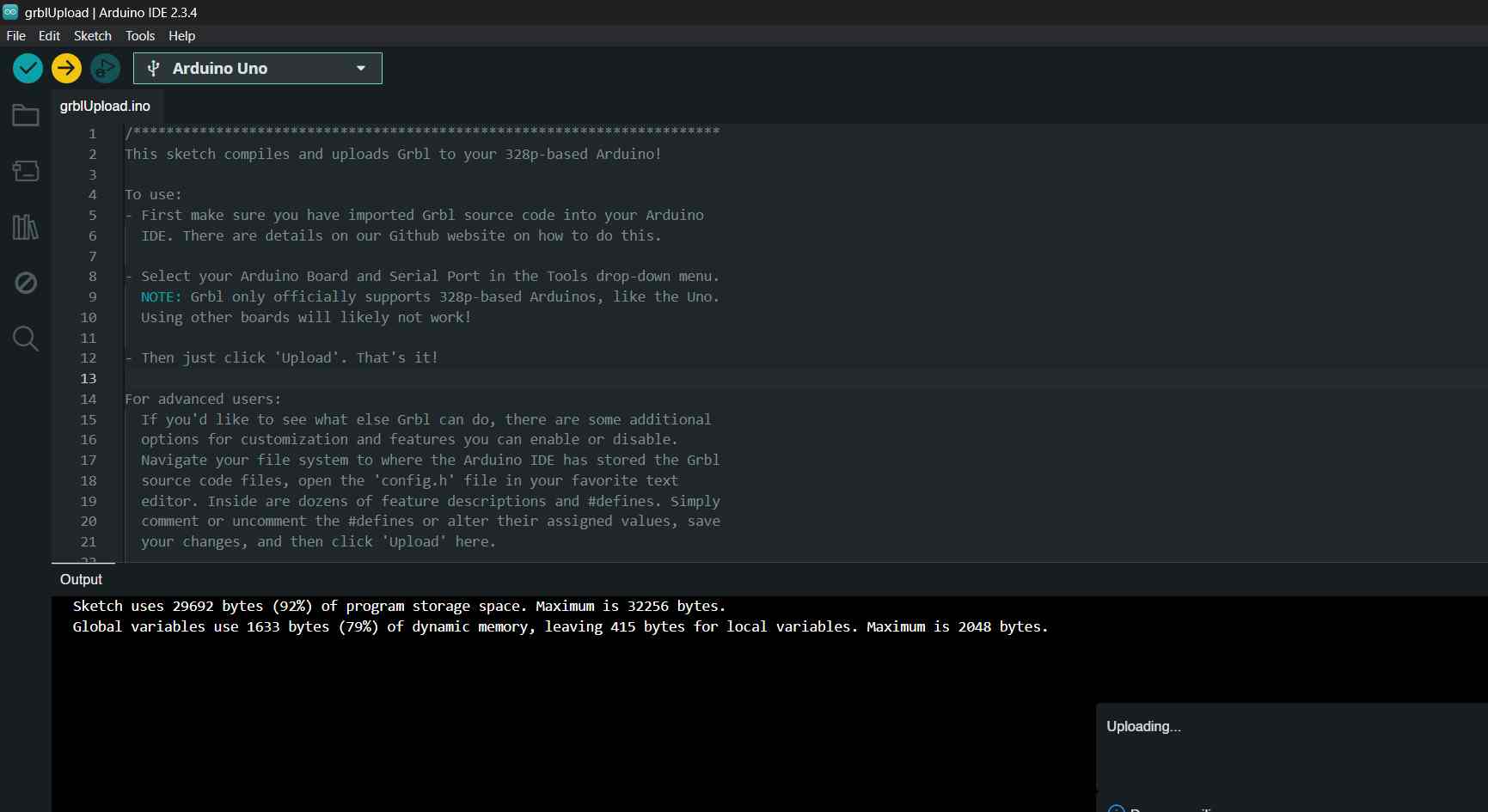
After verifying the grblUpload sketch, click the Upload button in the Arduino IDE to upload the GRBL firmware to your board.
Wiring Up the Electronics
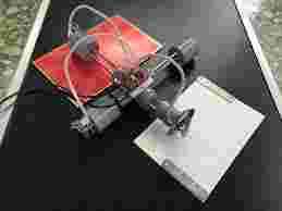
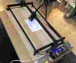
Once the firmware was installed, we moved on to wiring. We connected the stepper motors using A4988 driver modules and linked them to the Arduino. We also added limit switches to define the movement boundaries. For both plotters, we used a 12V power supply. One plotter is designed for pen plotting (drawing and writing), while the other is equipped for light engraving, so we tailored the wiring and connections accordingly.
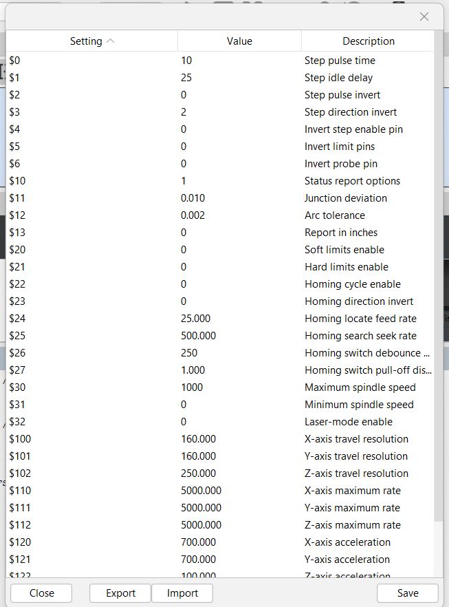
With everything wired up, to configure the GRBL settings. By typing $, we could view the default parameters. Then, we updated key settings like:
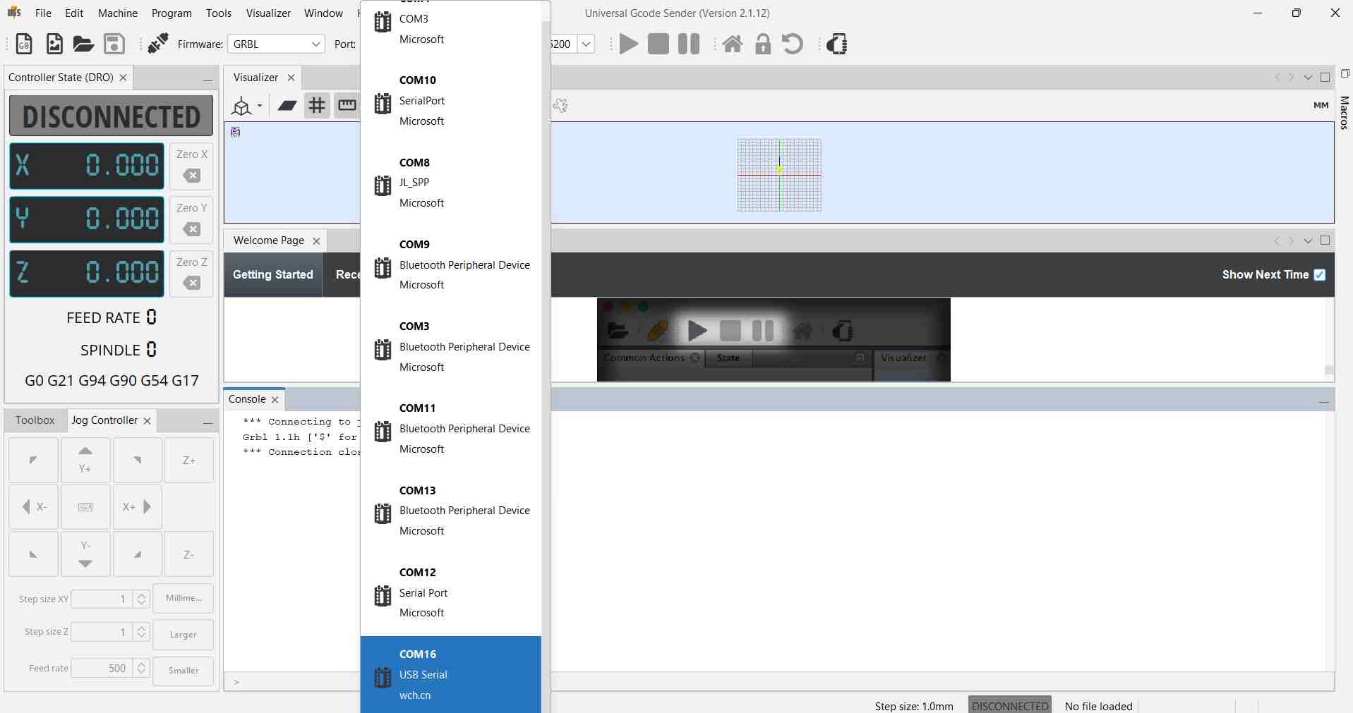
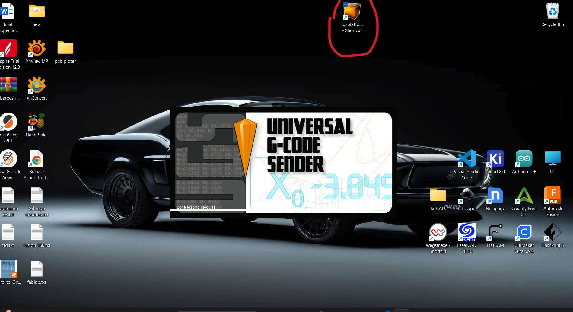
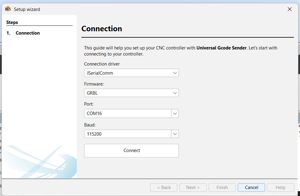
Open the UGS (Universal Gcode Sender) Software:
To begin controlling and communicating with your CNC machine or GRBL-based hardware, launch the Universal Gcode Sender (UGS) software on your laptop.
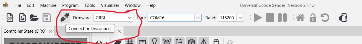
Select the correct port to which your CNC controller (such as Arduino with GRBL firmware) is connected.
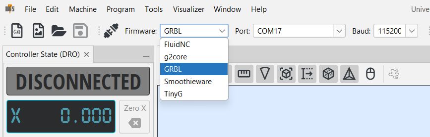
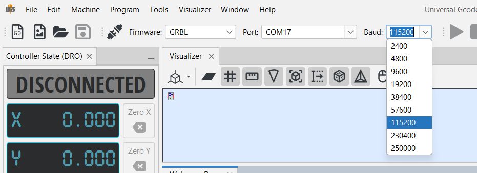
In the connection panel at the top of the UGS interface. Look for a dropdown menu labeled "Port" or "COM Port".
Click the dropdown — it will list all available serial ports. If you’re not sure which one is your device:
Unplug the USB cable and check the list. Plug it back in and see which new port appears. That’s your device's port (e.g., COM3, COM4, /dev/ttyUSB0, etc.).
Choose the appropriate baud rate — typically 115200 for GRBL.
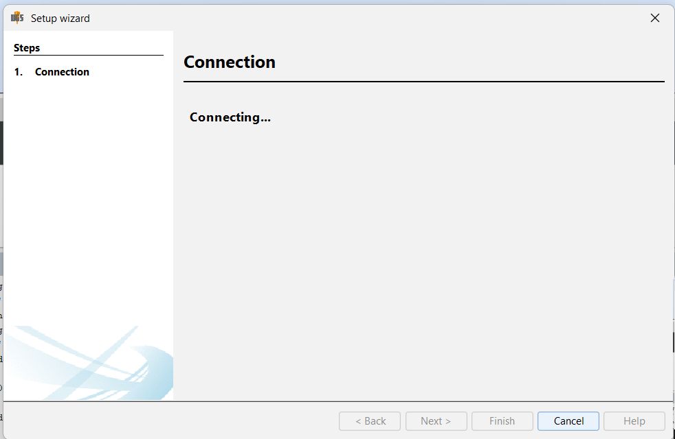
After verifying the port and baud rate, click on "Connect" to establish communication with the device.
Once connected, you will be able to see the machine's status and begin sending commands or G-code for execution.
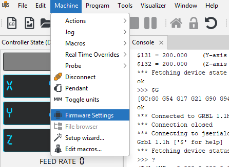
Now it’s time to configure your machine using UGS's Firmware Settings.
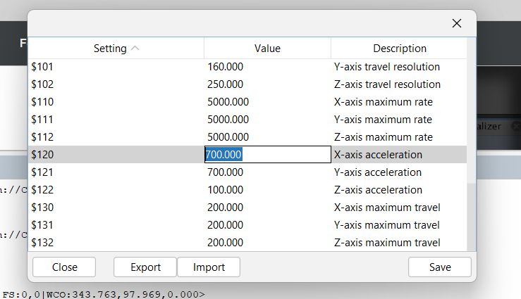
We reviewed the description and, based on that information, adjusted the values accordingly. It took some time to optimize and find the exact values, so we made adjustments that were as close as possible to the ideal settings.
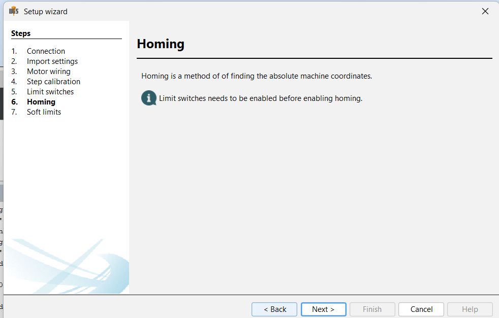
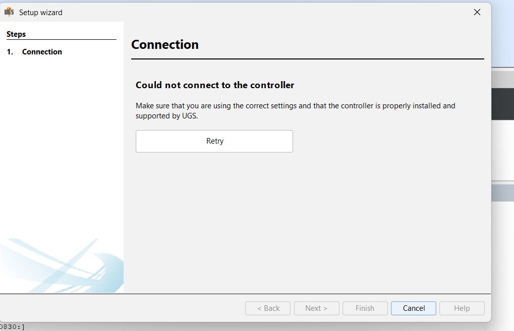
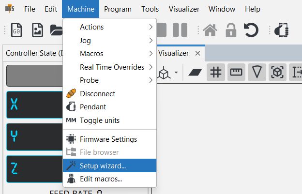
Now it’s time to configure your machine using UGS's Setup Wizard.
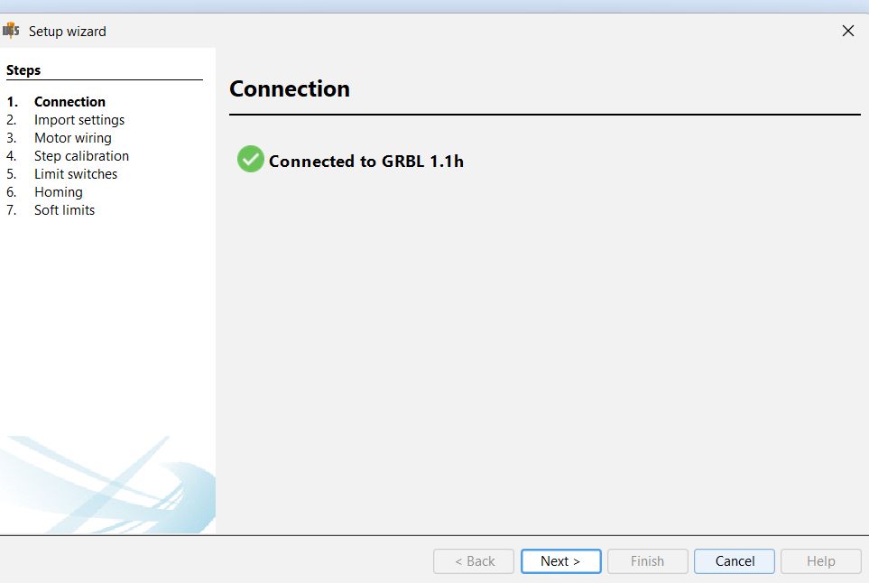
During the setup wizard process, we made a mistake by unintentionally unplugging the cable, which caused the connection to be lost. This interrupted the setup process, and we had to reconnect and continue from there.
After the settings, it connecting properly
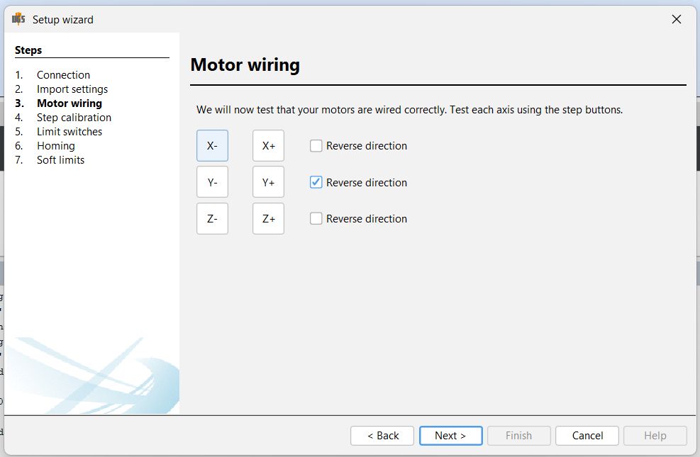
In the setup wizard, first ensure that the X and Y motors are properly connected to their respective ports on the control board. Check that the cables are securely plugged in and there are no loose connections.
If the motors were unplugged earlier, make sure the machine is powered off before reconnecting them. Once reconnected, power it back on and proceed to the motor configuration section in the setup wizard.
During this step, observe the direction in which the motors move. If you notice that the Y-axis motor is running in the opposite direction, there’s an option in the wizard to reverse the motor direction. Simply tick that option for the Y-axis.
After making this change, run a quick test from the wizard to confirm that the motors are moving correctly. Reversing the Y-axis direction when needed ensures proper movement and alignment, allowing everything to operate smoothly.
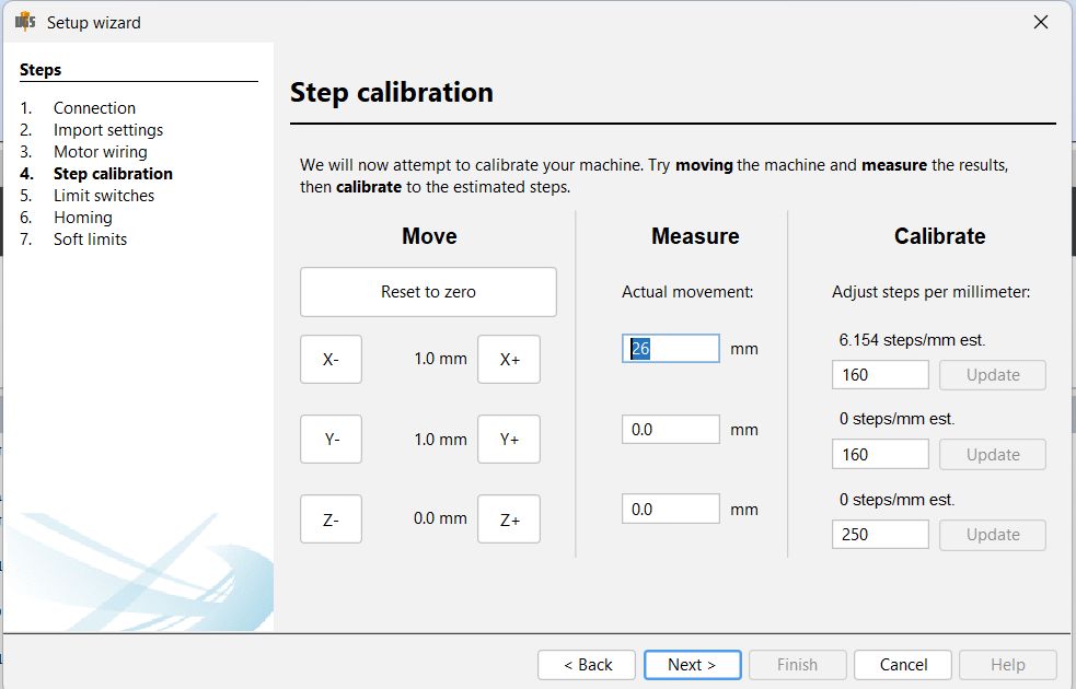
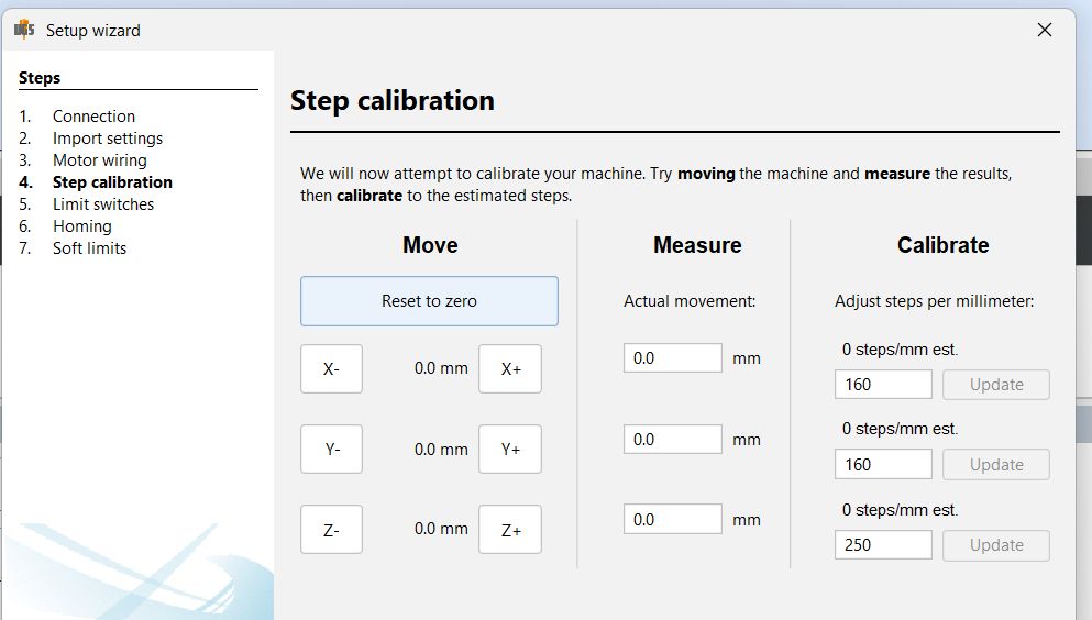
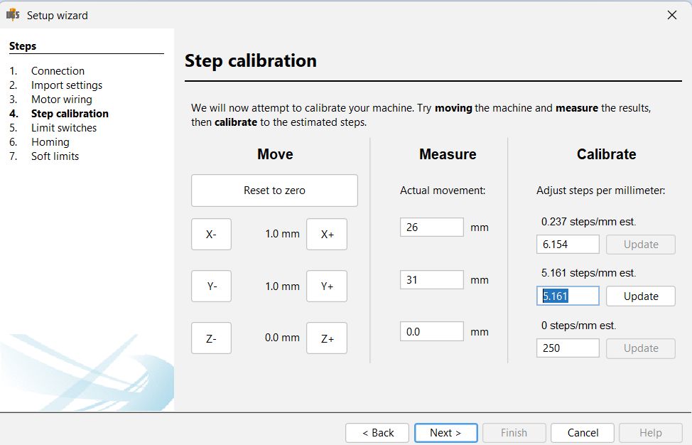
In the setup wizard, move to the step calibration section after motor wiring is complete. This step ensures that your machine moves the correct distance when given a command.
Begin by selecting one axis—typically the X or Y axis. Use a precise measuring tool like a ruler or caliper to mark a reference point on your machine’s gantry or base. Then, command the machine to move a specific distance, for example, 1mm.
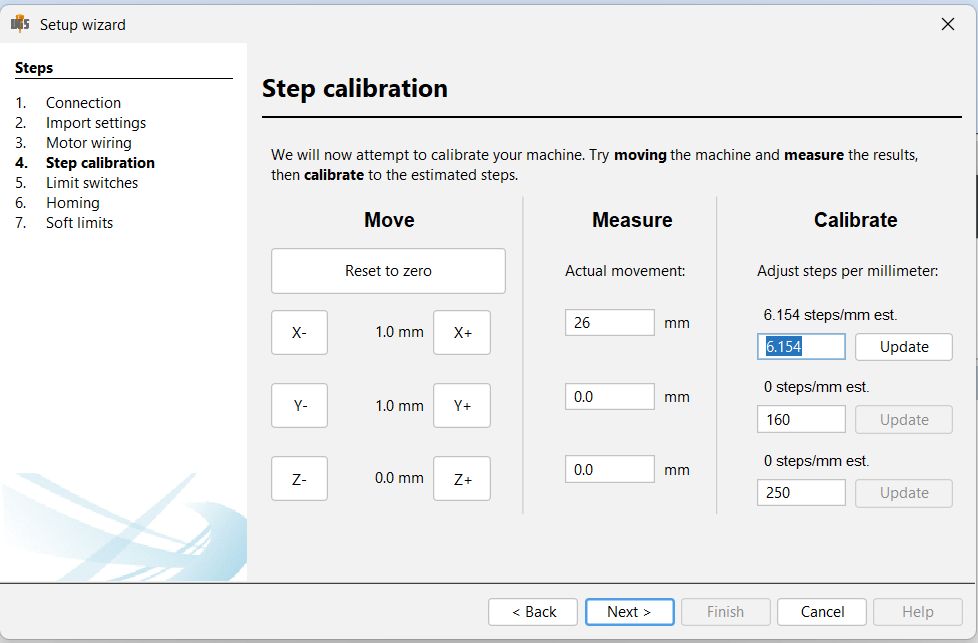
After the machine moves, measure the actual distance it traveled from your original reference point. If the actual distance is more or less than the commanded distance, you’ll need to adjust the steps-per-mm value.
There will be an option in the wizard to enter the actual distance traveled. Based on that, the software will automatically calculate and update the correct steps-per-mm value for that axis.
Repeat this process for both X and Y axes to ensure accurate movement. This calibration is important because even a small error in steps can affect the final output or print quality, especially in CNC
While setting up the plotters, we faced several issues—especially during the early testing stages with UGCS (Universal G-code Sender). One of the main problems was unexpected movement. For example, when we clicked to move the X-axis by a small amount (like 1 mm), the plotter moved a lot more than expected, sometimes jumping several millimeters in a single command.
This behavior made it clear that something was off in our configuration.
After investigating, we realized the issue was due to high acceleration and feed rate values in the GRBL settings. These values were too aggressive for the mechanical setup of our plotters. The stepper motors couldn’t keep up with the rapid commands, which led to overshooting and unstable movement.
During initial testing, we also noticed that the vibration was extremely high, especially when the motors tried to accelerate quickly. Based on our instructor’s suggestion, we reduced the acceleration values, and that made a big difference—the machine started running much more smoothly.
To fix the rest of the issues, we took a step-by-step approach:
Apart from tuning, we also ran into a power supply issue early on. Initially, we used a 12V 2A power supply, assuming it was enough. But the motors were weak and unresponsive, especially when multiple axes moved together. Later, we found that the stepper motors were wired in series, which increased the load. To fix it, we upgraded to an 18V 3–4A power supply, which stabilized the system.
Even after resolving the power problem, we still experienced movement glitches, which we were able to solve with careful parameter tuning. It took time and repeated testing, but eventually, both plotters achieved accurate and consistent performance.
Link to Part Files: Link
Link to worksheet: Link