Week 10: Output Devices : Relay Module
We have measured the power consumption of an output device, documented the process on the group work page, and reflected on our learning on individual pages.
Visit our Group Assignment Page to explore our findings and methodologies.
This page documents the individual assignment to add an output device to a microcontroller board, measure its power consumption, and program it to perform a task. The output device selected for this task was a 5V single-channel relay module. The relay, a widely used electronic component, functions as a switch controlled by electrical signals. By integrating this device into a microcontroller board, I explored its functionality, interfacing requirements, and programming techniques.
Understanding the Relay Module
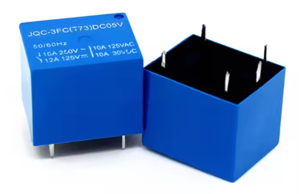
The 5V single-channel relay module is an essential component widely used in electronics and embedded systems for switching high-power circuits using low-power control signals. Its compact design, reliability, and versatility make it a popular choice for both hobbyists and professionals. This module plays a crucial role in interfacing microcontrollers with devices or circuits that require more current or voltage than the microcontroller can handle directly.
Core Features and Components
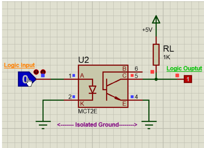
The relay module is built around an electromechanical relay, which is the heart of the device. This relay is responsible for the physical switching of circuits. The module also integrates several other components to ensure seamless operation. One key feature is the inclusion of an optocoupler, which provides electrical isolation between the control circuit (low voltage) and the load circuit (potentially high voltage). This isolation is crucial for protecting sensitive components and ensuring the safety of the system and the operator.
Relay Overview
A relay is an electrically operated switch used to control high-power or high-voltage circuits with low-power signals. It consists of an electromagnet, armature, and a set of contacts, enabling efficient isolation between control and output circuits.
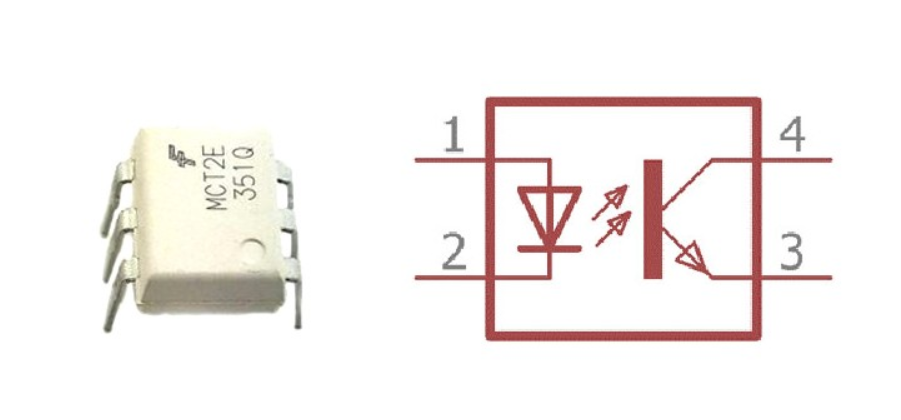
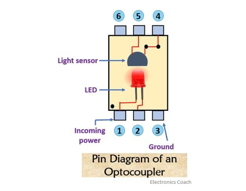
Optocoupler Overview
An optocoupler, also known as an optoisolator, is a component that transfers electrical signals using light to provide isolation between input and output circuits. It typically consists of an LED and a photodetector housed in a single package, ensuring safe signal transmission while preventing electrical interference.
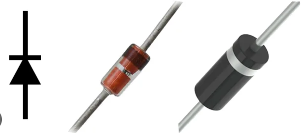
Flyback Diode Overview
A flyback diode, also known as a freewheeling diode, is used to protect circuits from voltage spikes caused by inductive loads, such as relays, motors, or solenoids. It provides a path for the inductive current when the power is switched off, preventing damage to components and ensuring safe operation.

Other critical supporting components include diodes and transistors. The diode, often a flyback diode, prevents voltage spikes generated when the relay coil is de-energized from damaging other components. The transistor acts as a switch, enabling the low-power signal from the microcontroller to energize the relay coil effectively.
Power Requirements and Operation
Operating at a 5V DC supply, the relay module is compatible with most microcontroller systems, including Arduino, Raspberry Pi, and other development boards. The relay coil consumes a small amount of current (typically 70-80 mA), which is easily provided by the microcontroller’s GPIO pins, often with a transistor buffer for added efficiency. Once the coil is energized, it creates a magnetic field that moves an internal armature, changing the state of the relay contacts.
This module is capable of controlling AC or DC loads. For instance, it can be used to switch on a light bulb, control a motor, or activate a high-power device. The switching mechanism is robust and reliable, making it suitable for both simple and complex applications.
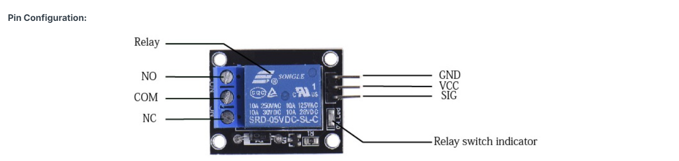
Terminals and Their Functions
The relay module has three main terminals for connecting the load circuit: Common (COM), Normally Open (NO), and Normally Closed (NC). These terminals play distinct roles:
- Common (COM): This terminal serves as the shared contact point for the load circuit. It is connected to either the NO or NC terminal depending on the relay’s state.
- Normally Open (NO): This terminal is disconnected from the COM terminal when the relay is in its default (de-energized) state. When the relay is activated, the NO terminal connects to COM, completing the circuit and allowing current to flow to the load.
- Normally Closed (NC): This terminal is connected to the COM terminal when the relay is in its default state. Activating the relay disconnects the NC terminal from COM, breaking the circuit.
Applications and Use Cases
The versatility of the 5V single-channel relay module allows it to be used in a wide range of applications. Common use cases include:
- Home Automation: Controlling lights, fans, and other appliances remotely using microcontrollers or smart systems.
- Industrial Automation: Managing machines or equipment that require higher voltage or current than a microcontroller can handle directly.
- Safety Systems: Activating alarms, emergency shut-off circuits, or other safety mechanisms.
- IoT Projects: Integrating with IoT devices to enable remote control of electrical appliances through the internet.
- Power Management: Switching between power sources or managing energy distribution in complex systems.
Advantages of the Relay Module
The module's compact design makes it ideal for projects where space is a constraint. Its low power consumption ensures that it can be operated directly from a microcontroller without additional power supplies in most cases. The integration of an optocoupler enhances safety by isolating the control and load circuits, reducing the risk of damage due to voltage spikes or surges. Additionally, the relay module supports both AC and DC loads, offering great flexibility.
Practical Considerations and Limitations
While the relay module is a powerful tool, there are several factors to consider when using it:
- Power Ratings: Ensure that the relay's voltage and current ratings are sufficient for the load. Exceeding these ratings can damage the relay or cause it to fail prematurely.
- Switching Speed: Relays are electromechanical devices and are not as fast as solid-state switches. For high-speed switching applications, alternative solutions like MOSFETs or SSRs may be more suitable.
- Noise and Interference: When switching inductive loads like motors or solenoids, the relay can generate electrical noise that may interfere with nearby circuits. Proper filtering and shielding techniques can mitigate this issue.
- Mechanical Wear: Over time, the mechanical components of the relay can wear out, especially if the relay is used in high-frequency applications. It’s important to consider the relay’s rated lifespan.
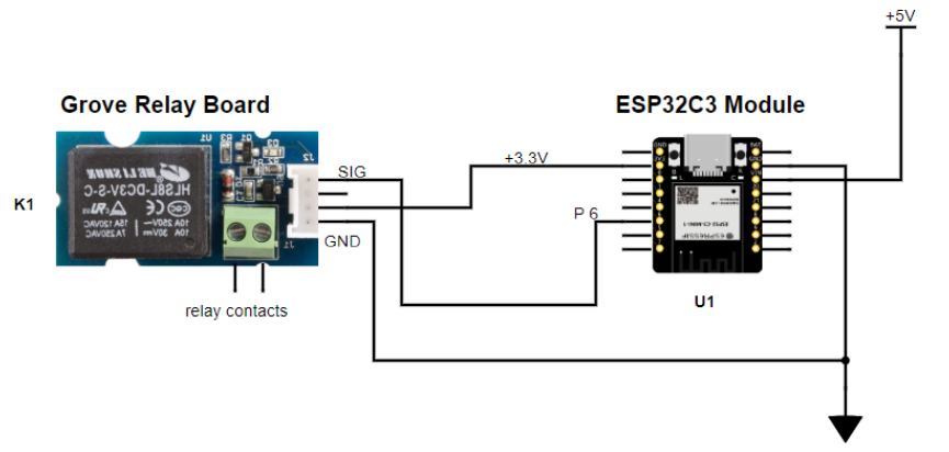
Interfacing the Relay with a Microcontroller
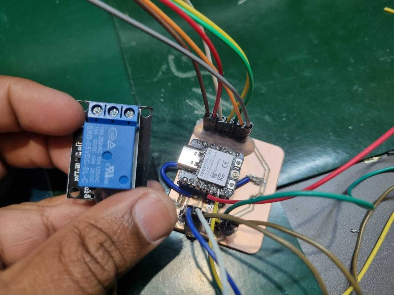
To interface the relay module with my custom-designed microcontroller board, I established the following connections:
- Signal (IN): Connected to a GPIO pin on the microcontroller for controlling the relay state.
- VCC: Connected to the 5V power output of the microcontroller board.
- GND: Connected to the ground pin of the microcontroller board.
A flyback diode was added across the relay's coil to protect the circuit from voltage spikes generated during switching operations. Additionally, a pull-down resistor was used on the control pin to prevent noise interference and ensure the relay remained in a defined state when the microcontroller pin was floating.
Programming the Relay
The relay was programmed using the Arduino IDE and controlled via a GPIO pin. Below is a snippet of the code used to toggle the relay ON and OFF:
#define RELAY_PIN 7

void setup() {
    pinMode(RELAY_PIN, OUTPUT); // Set relay pin as output
    digitalWrite(RELAY_PIN, LOW); // Ensure the relay is OFF initially
}

void loop() {
    // Turn the relay ON
    digitalWrite(RELAY_PIN, HIGH);
    delay(1000); // Keep it ON for 1 second

    // Turn the relay OFF
    digitalWrite(RELAY_PIN, LOW);
    delay(1000); // Keep it OFF for 1 second
}
The relay's state is toggled by sending HIGH or LOW signals to the control pin. This simple program demonstrated the functionality of the relay and provided a foundation for more complex applications.
Results
The 5V single-channel relay module successfully controlled an external load based on the microcontroller’s output signals. The power measurements confirmed its efficiency, and the implemented safety measures ensured reliable operation. This project demonstrated the workflow involved in interfacing an output device with a microcontroller, measuring its performance, and programming it for practical applications.
5 Volt Relay Module (5V Relay Module)