Week 17
Assignment: wildcard week
Individual assignment
- Design, lasercut, and document a parametric construction kit, accounting for the lasercutter kerf, which can be assembled in multiple ways.
- Cut something on the vinyl cutter.
Introduction to CAM (Computer-Aided Manufacturing)
Computer-Aided Manufacturing (CAM) is a digital fabrication method that uses specialized software and automated machinery to produce parts with high accuracy and precision. CAM plays a critical role in modern manufacturing, enabling faster production, consistent quality, and optimized resource usage.
What is CAM?
CAM software takes a 3D design created in CAD (Computer-Aided Design) and translates it into machine-readable instructions, typically G-code, which drives CNC machines, laser cutters, and other automated tools.
CAM Capabilities
Beyond just toolpath generation, CAM also assists in production planning, process management, inventory tracking, and logistics—making it an integral part of end-to-end digital manufacturing.
Primary Goals of CAM
The primary goals of CAM are:
- To enhance manufacturing efficiency
- Reduce material and energy waste
- Improve consistency and quality of the final product
- Enable complex geometries that are difficult to achieve through manual methods
Learn More About CAM
Detailed CAM Guide: What is Computer-Aided Manufacturing (CAM)?
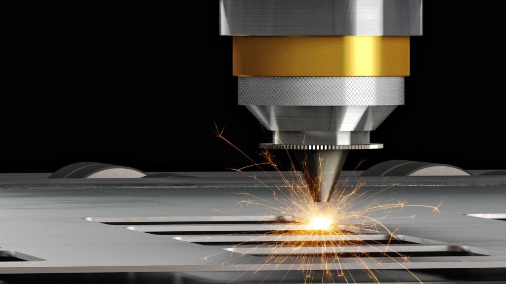
About the Metal Laser Cutting Process
Metal laser cutting is a precise method that uses a high-powered laser beam to melt or vaporize metal, producing clean cuts with minimal distortion. It is commonly used in manufacturing, prototyping, and metal fabrication.
Key Steps
- Design Preparation: Cutting patterns are created using CAD or 2D design software and exported as DXF or similar formats.
- Machine Setup: Laser power, speed, focus, and assist gas (like nitrogen or oxygen) are configured based on material type and thickness.
- Cutting: The laser follows the design path, cutting the metal accurately with no physical contact.
- Post-Processing: Cut parts are cooled, cleaned, and deburred as needed for final use.
Learn More About Metal Laser Cutting
Comprehensive Guide: How Does Metal Laser Cutting Work?
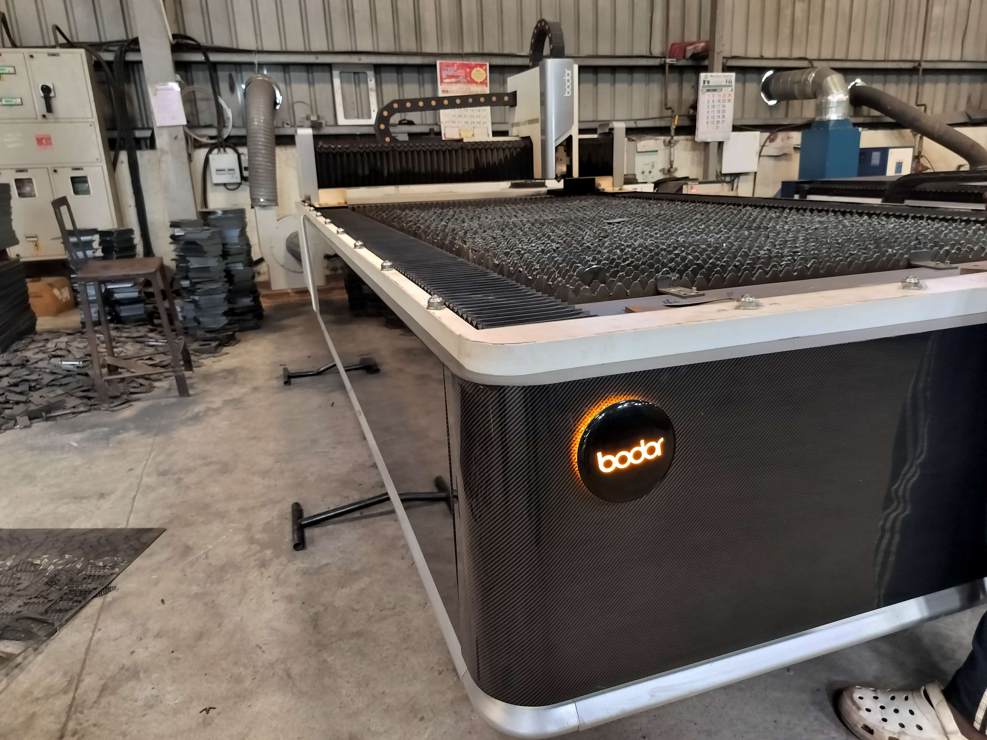
Machine Introduction & Specifications
Bodor is a well-known brand in industrial laser cutting, offering high-speed and high-precision metal cutting systems. The model used in this project supports automated control and is suitable for various metal types.
🔧 Key Technical Specifications
| Feature | Details |
|---|---|
| Laser Type | Fiber Laser (common in Bodor models) |
| Laser Power | 1000W to 6000W (varies by model; ours: ~1500W) |
| Supported Formats | DXF, DWG, AI, PLT, SVG, G-code, NC |
| Cutting Materials | Stainless steel, mild steel, aluminum, brass |
| Max Cutting Thickness | - Mild Steel: up to 12 mm - Stainless Steel: up to 6 mm - Aluminum: up to 4 mm |
| Positioning Accuracy | ±0.03 mm |
| Repositioning Accuracy | ±0.02 mm |
| Max Moving Speed | ~140 m/min (depends on model) |
| Control Software | BodorPro or CypCut (commonly used) |
| Cooling System | Water-cooled |
| Assist Gases | Nitrogen, Oxygen, Air |
| Machine Bed Size | Varies; commonly 1500 mm × 3000 mm (5 ft × 10 ft) |
Workflows Used in the Chosen Process
1. Design & CAD Workflow
Initiated with a conceptual sketch of the final object. Developed precise 2D CAD geometry in Fusion 360/AutoCAD. Checked design for cut-tab joints, correct orientation, and sequence of cuts.
2. File Preparation Workflow
Exported CAD drawing as .DXF to preserve vectors and scaling. Imported the .DXF into the laser control software (like LightBurn or RDWorks).
Sorted cut paths by material thickness and cut order: Tabs and etching first with lower power/high speed. Perimeter cuts last with higher power/lower speed for clean edges.
3. Machine Setup Workflow
Loaded material: clean-off, flattened 3 mm mild steel sheet. Calibrated machine settings based on manufacturer specs and previous tests (e.g., 90% power, 25 mm/s for etching; 100% power, 12 mm/s for cuts). Focus adjusted automatically via Z-probe.
4. Dry Run Validation
Conducted an air-run to confirm path alignment and part nesting. Adjusted spacing and path orientation to minimize kerf effects and material waste.
5. Cutting Execution
Engaged laser cuts in sequence. Monitored gas flow and dust extraction to ensure optimal clarity and safety. Removed and inspected parts for any undercuts or sharp burrs immediately after cutting.
6. Post-Processing
Lightly filed any burrs using a metal file. Cleaned pieces with isopropyl alcohol to remove residue. Checked fit of joints and re-filed as needed until snug.
7. Assembly Workflow
Assembled via tab-and-slot joints with emphasis on perfect alignment. Added temporary clamps where necessary to align parts during bonding. For structural stability, reinforced with spot welds or rivets where required. Final sanding ensured smooth edges and clean aesthetics.
Design & File Preparation
Sketching and Modeling in Fusion 360
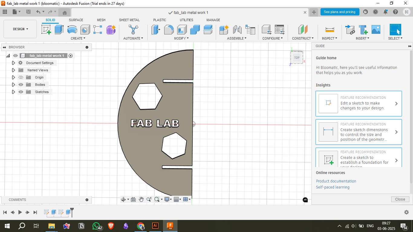
- I started by creating a 2D sketch on the XY plane using the Sketch tools (Line, Circle, Text, Polygon).
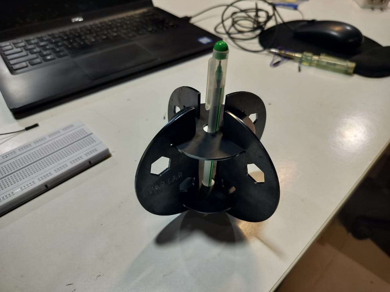
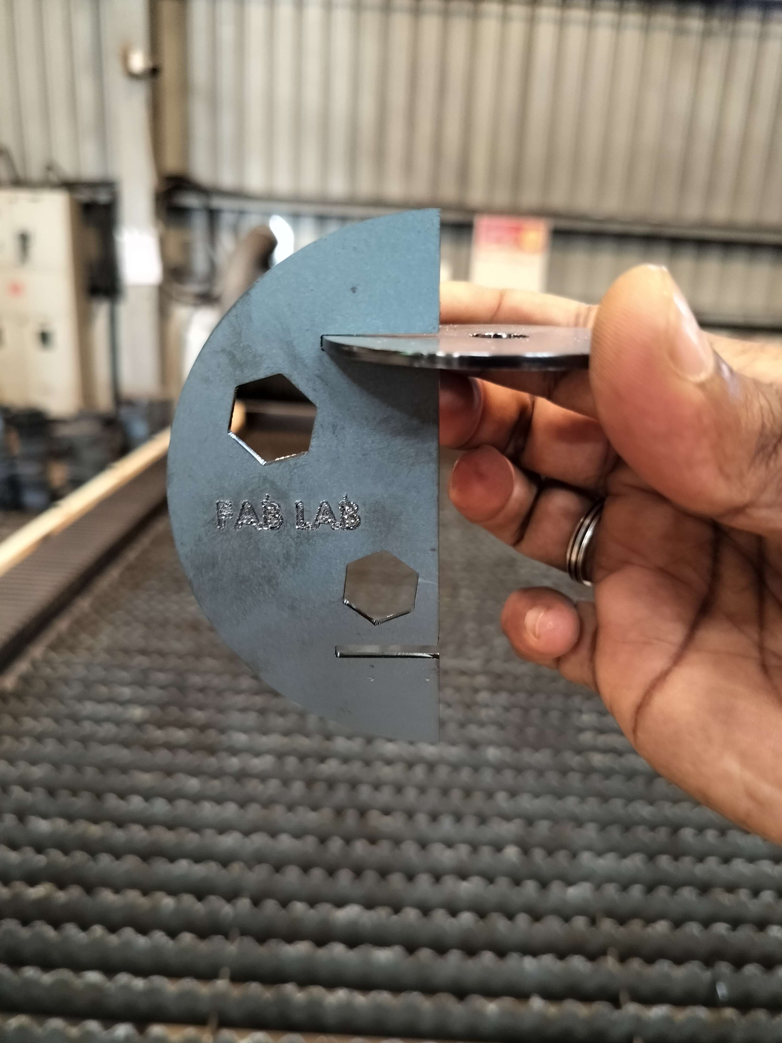
- The design includes circular plates with hexagonal cutouts and embedded text ("FAB LAB").
- I used extrude and mirror features to turn sketches into 3D bodies and prepare them for visual assembly.

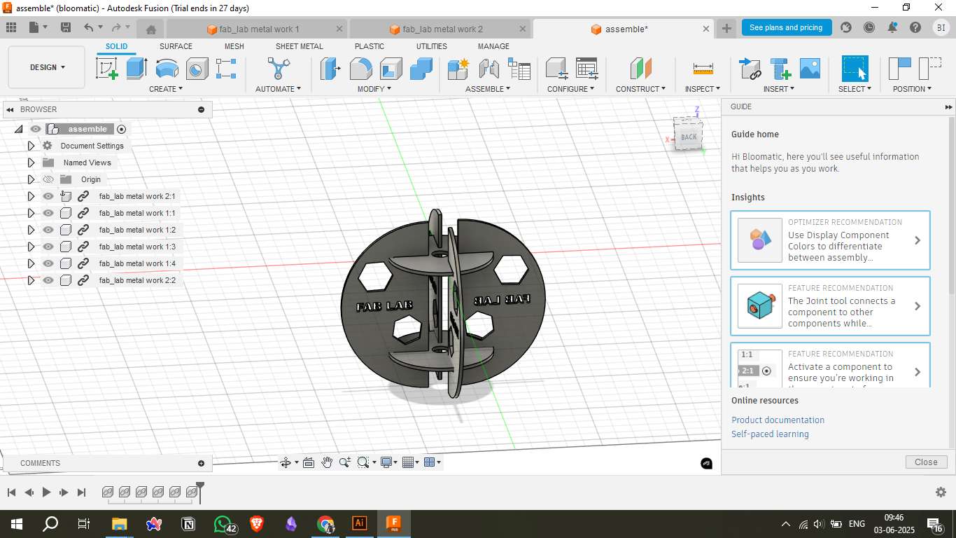
Assembly Visualization
- Multiple parts were assembled using the Joint tool in Fusion 360 to verify fit and alignment.
- This helped ensure that the final laser-cut parts would interlock and align properly during physical assembly.
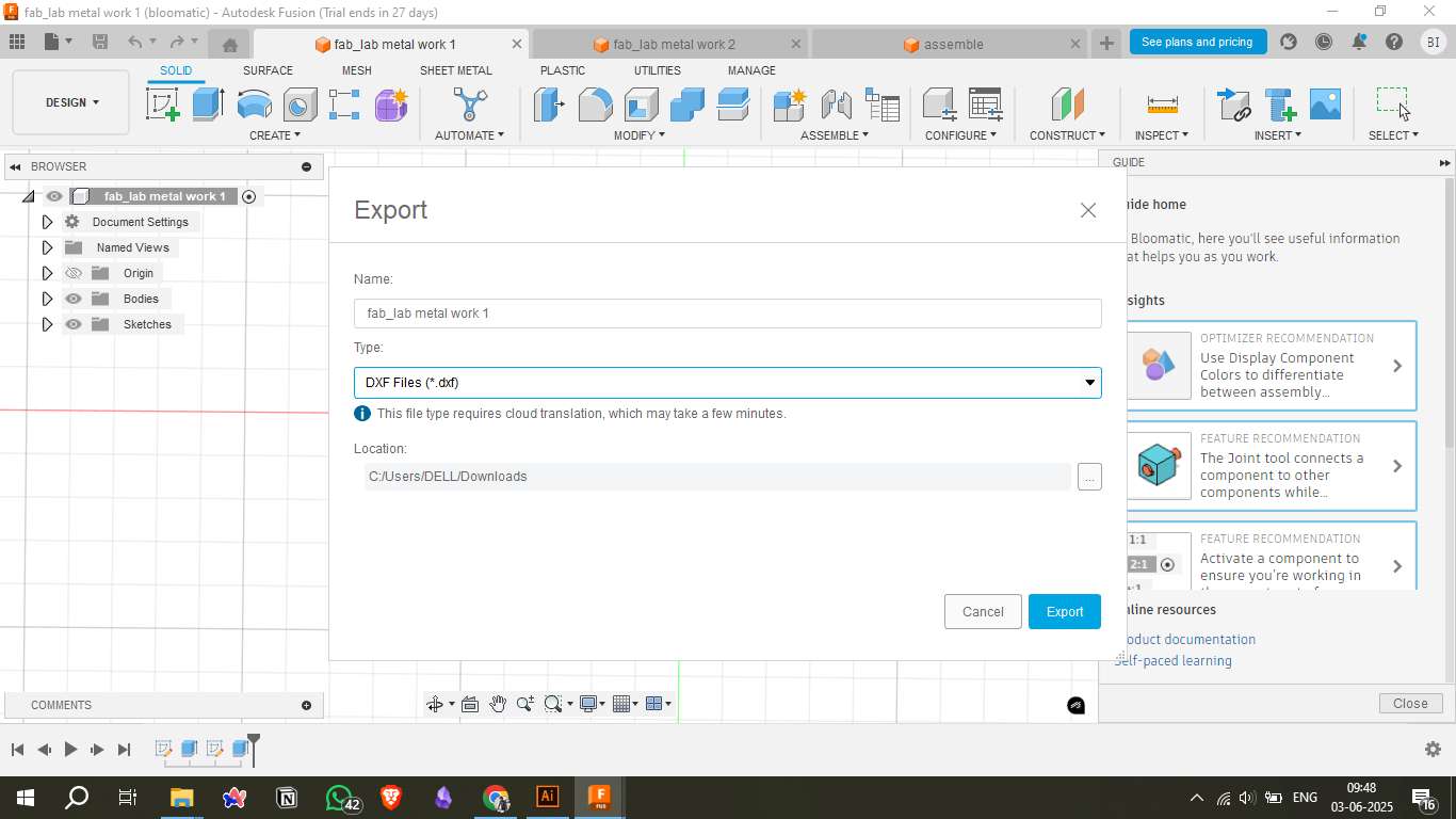
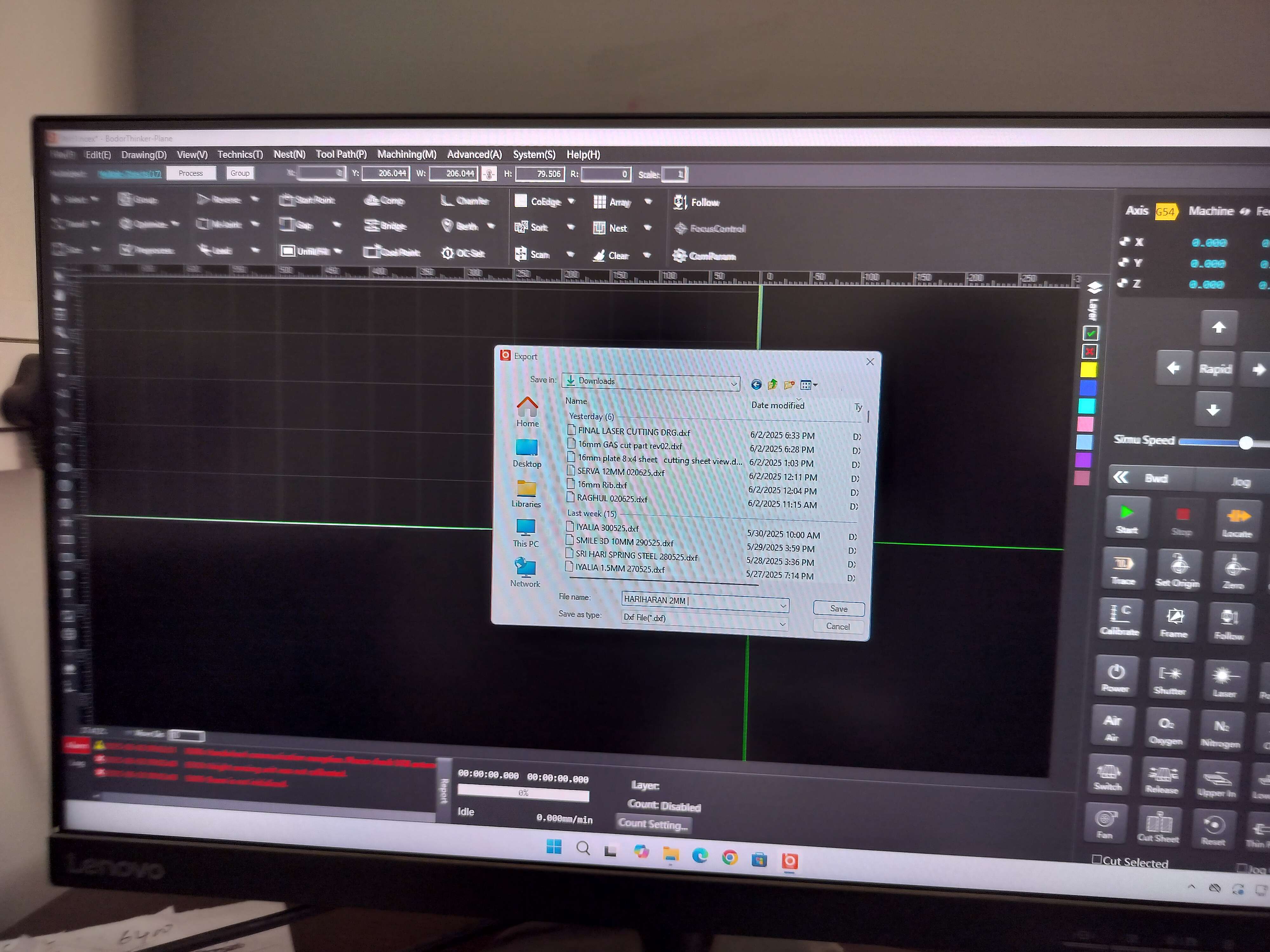
DXF Export for Laser Cutting
- After finalizing the sketches, I exported them as DXF files, which are compatible with laser cutting software.
- Fusion 360 provides direct DXF export from the sketch environment.
File Conversion and Import
- The exported DXF files were converted to DWG format (if required) to ensure compatibility with the Bodor Laser Software.
- Files were imported into the Bodor interface for toolpath planning and simulation.
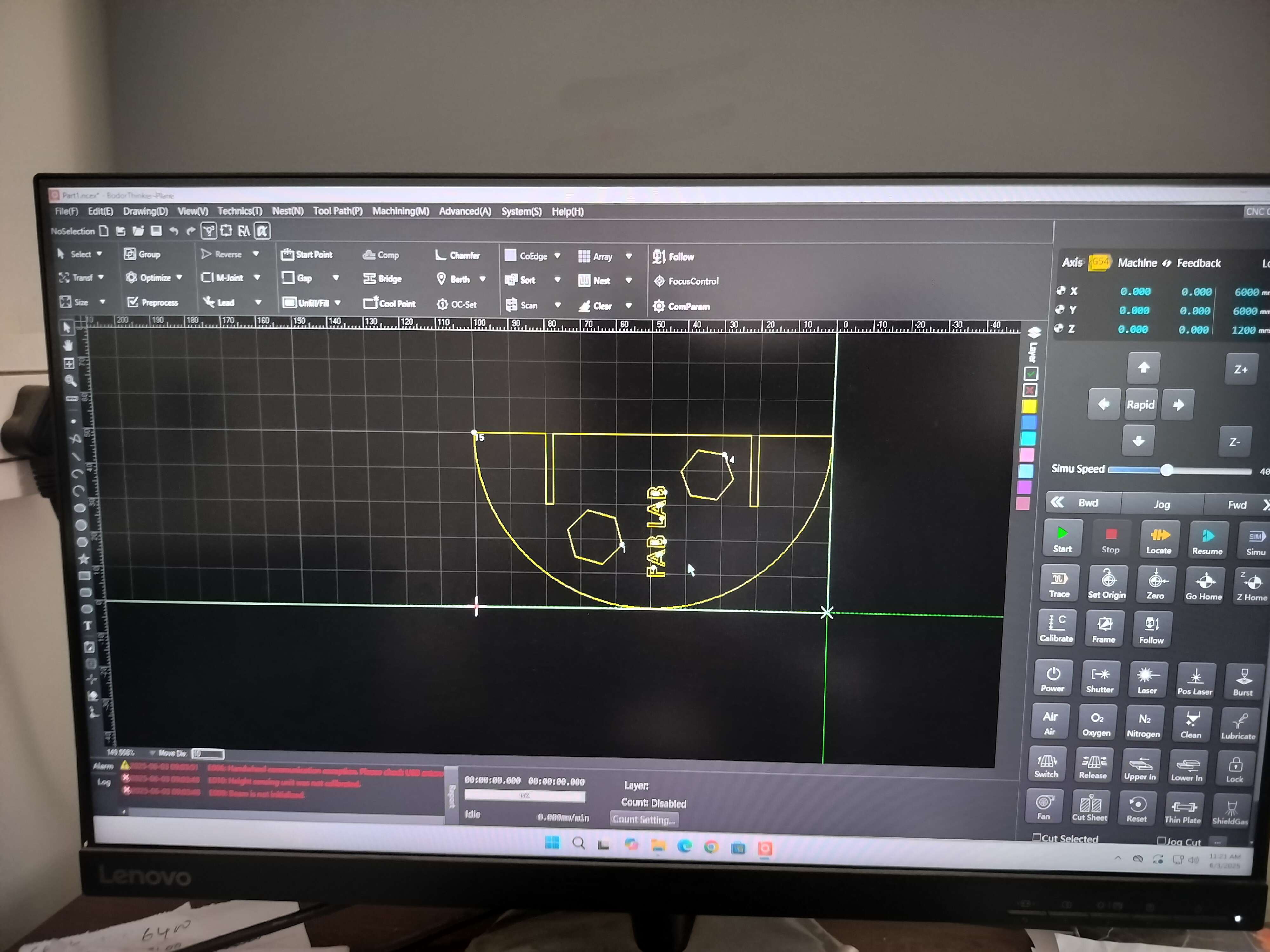
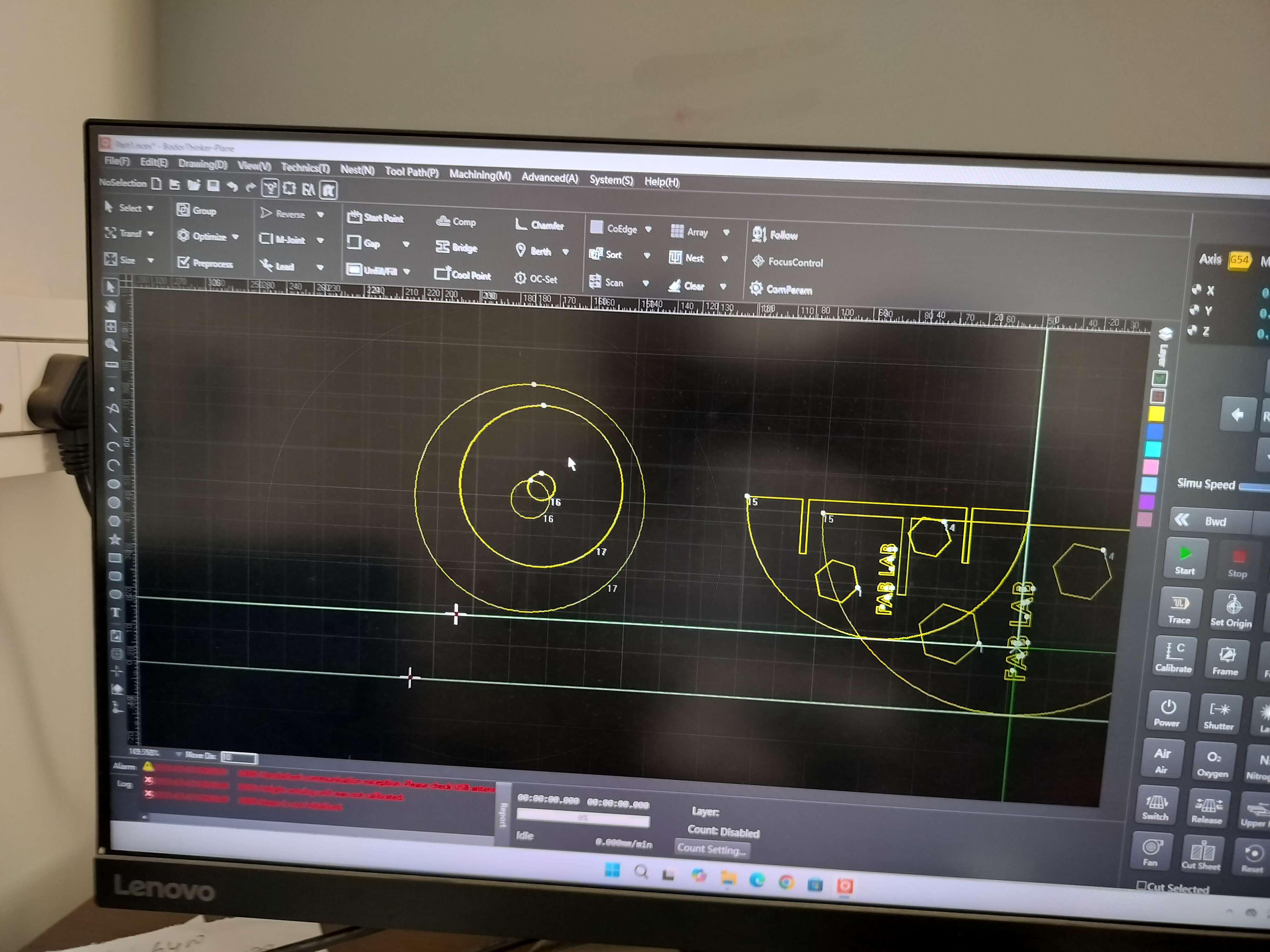
Bodor Software Setup
Inside the Bodor control software, I:
- Positioned the design
- Checked scale and orientation
- Set tool paths and starting points
- Adjusted simulation speed and previewed the motion path before cutting
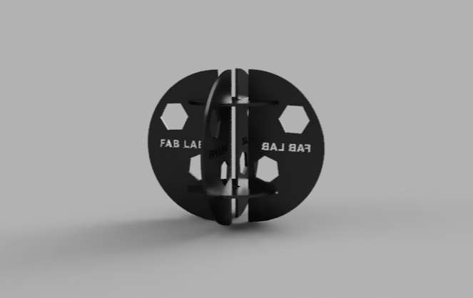
3D View / Exploded View
The 3D model was created in Fusion 360 to visualize the final assembly. It features two interlocking circular plates with hexagonal cutouts and engraved "FAB LAB" text.
Processes (and Materials)
1. Material Selection
Mild Steel (3 mm thick): Ideal for strength-to-weight and cost-effectiveness. Compatible with CNC laser cutting (fast cutting speed, clean finish).
Alternative Materials Considered: Aluminum (3 mm): Lighter but required slower speed and higher maintenance due to reflectivity. Stainless Steel (2 mm): Offered better corrosion resistance at higher cost and lower cutting speed.
2. Process Selection
Laser Cutting was selected due to: High precision and reproducibility. Clean, narrow kerf that enables snug interlocking joints without additional finishing. Suitability for prototyping and batch production.
Complementary Processes: Light grinding and filing for minor deburring. Spot-welding or riveting for enhancing structural integrity where glue-free assembly was required.
3. Process Justification
High Detail Accuracy: Laser cutting - 0.1 mm precision, perfect for tight joints
Structural Stability: Mild steel + spot welds - Provides strength and lasting durability
Assembly Fitment: Tight-tab design + cleaning - Enables snug joining without fasteners
Surface Finish: Filing + alcohol cleaning - Smooth edges, ready for any coating or paint
Safety & Efficiency: Protective gloves + goggles - Required for laser operation and grinding
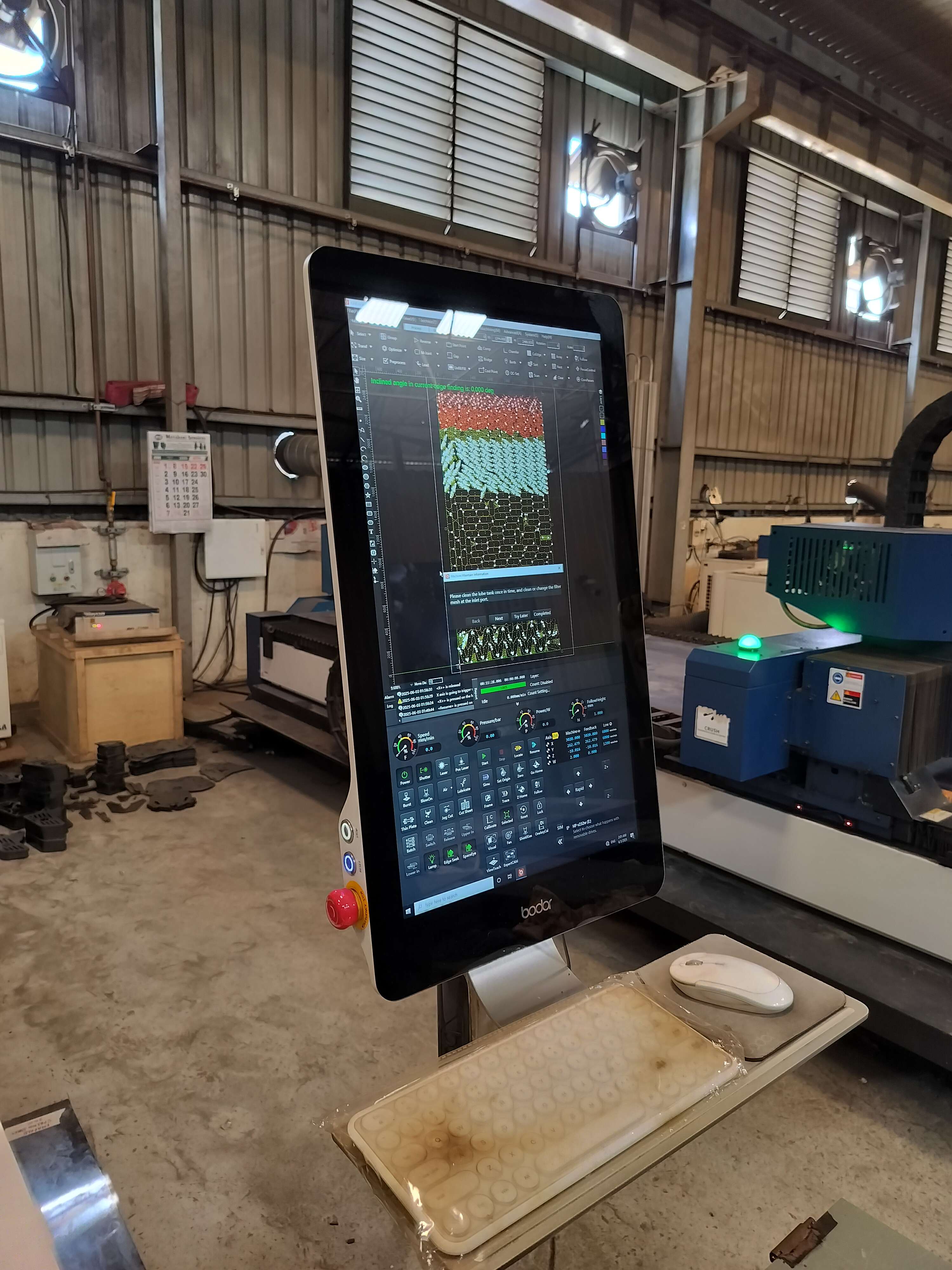
Feeding the File to Machine
Process Overview
- The DXF file was imported into the Bodor software.
- The design layout was adjusted for correct positioning on the sheet metal.
- Machine parameters such as cutting power, speed, focus height, assist gas type (N₂ or O₂), and piercing delay were configured based on the metal thickness.
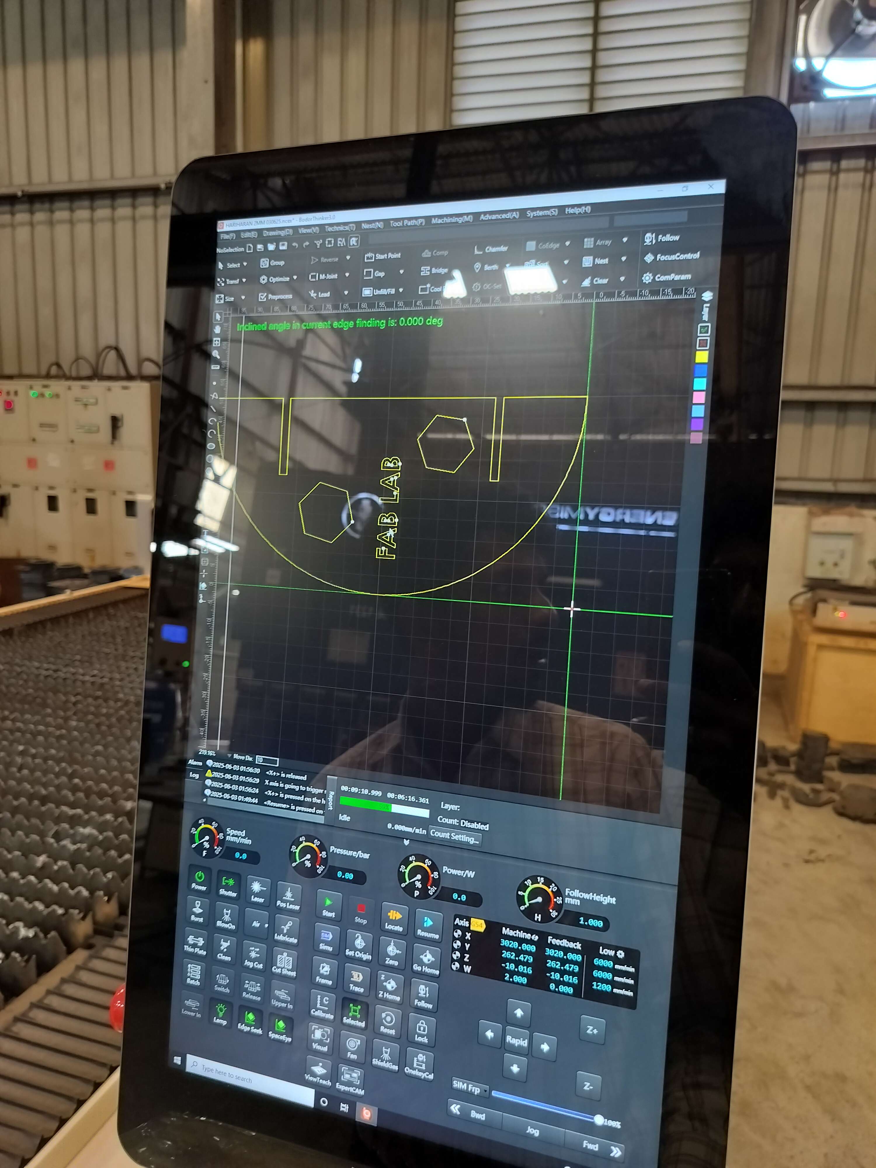
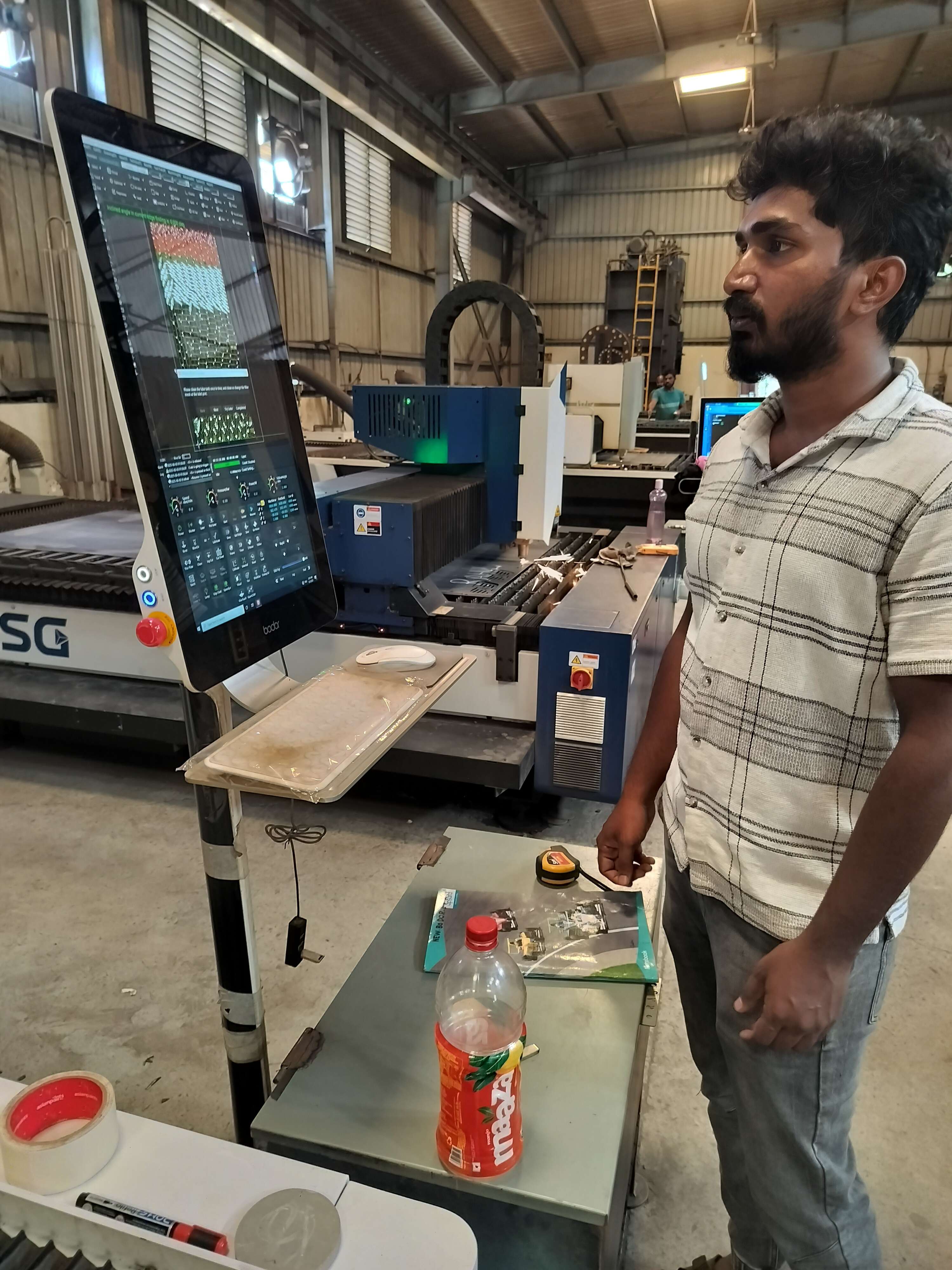
Operator Setup
- The operator used the touch interface to fine-tune settings like cut height, pulse frequency, and pressure values.
- The origin was set by jogging the laser head to the desired starting point on the sheet.
- A simulation preview was run to verify the toolpath before cutting began.
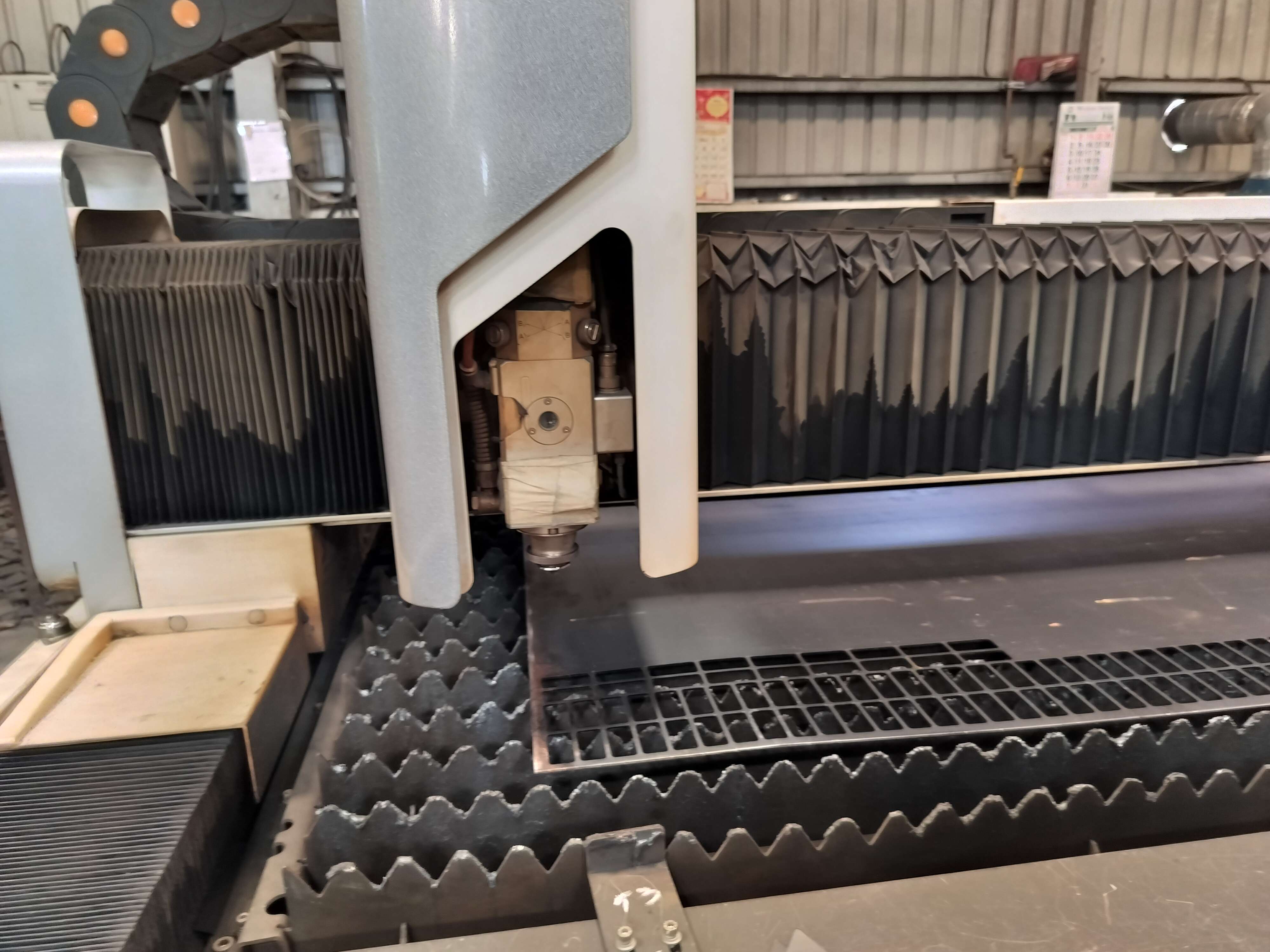
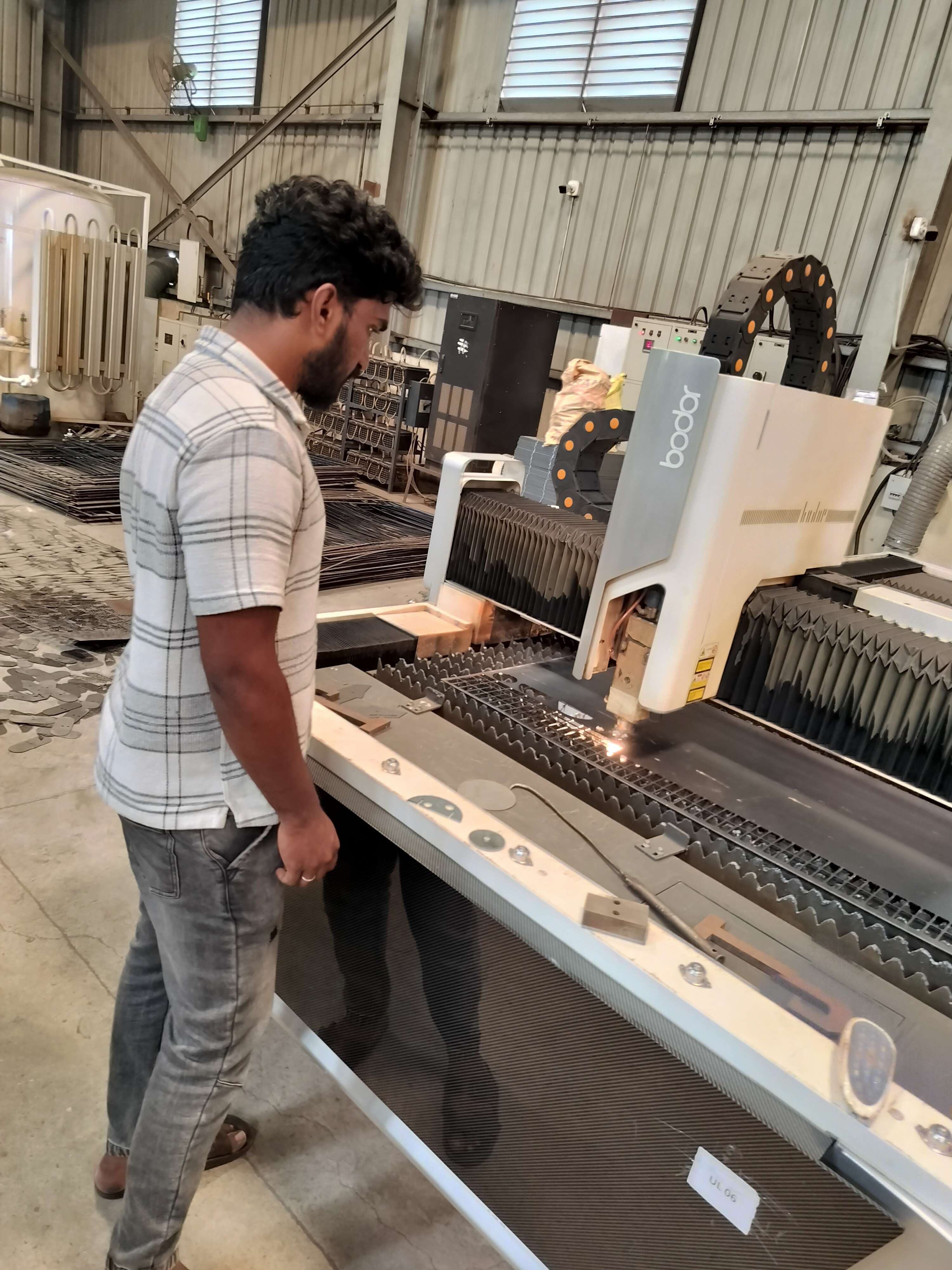
Cutting Process
Execution Steps
- The operator started the cutting job from the machine's control panel.
- The laser head automatically moved to the set origin and began tracing the imported DXF design.
- High-powered laser beams precisely cut through the metal sheet, guided by the configured speed, power, and assist gas settings.
Key Observations
- The laser maintained a consistent height and intensity throughout the process.
- Clean, burr-free edges were produced, and the hexagonal cutouts and text came out with sharp definition.
- Safety measures, including protective enclosures and operator distance, were maintained during cutting.
Post-Processing & Assembly
Post-Processing
After cutting, the metal parts were carefully removed from the laser bed. The edges were clean with minimal burrs, thanks to precise laser settings.
- Surface Cleaning: Minor oxidation was wiped off the surface.
- Fit Check: Each part was inspected for accuracy and slot dimensions.
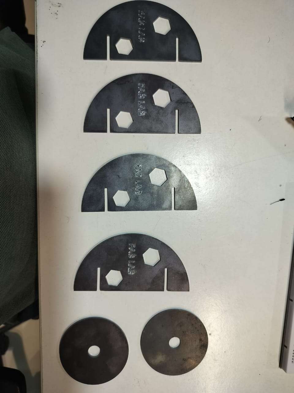
Assembly
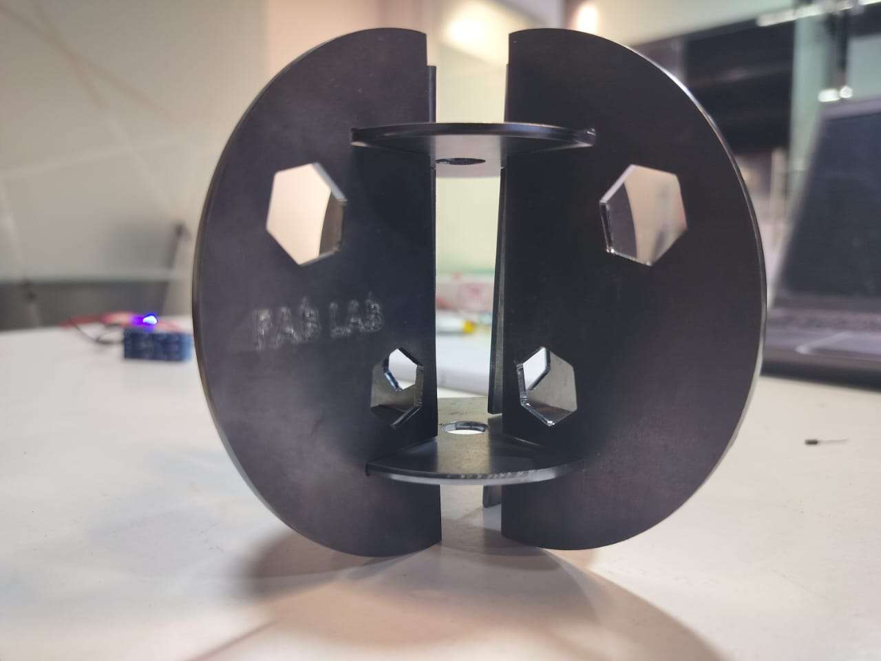
- The semicircular and circular parts were manually assembled using the interlocking tabs and slots.
- The joints were perfectly aligned, and the parts fit snugly without the need for glue or screws.
- The engraved "FAB LAB" text was clearly visible and added a neat branding touch to the final piece.
Hero Shot