
Week 16
Assignment: System Integration
Individual assignment
- Design and document the system integration for your final project
System Integration
System Integration is the process of bringing together various subsystems—mechanical, electronic, and software—into one unified functioning system. It ensures that all individual components of a project work together seamlessly to perform the intended operation.
Digital Fabrication Context
In the context of digital fabrication and projects like those in Fab Academy, system integration means combining:
- Mechanical systems (like enclosures, mounts, or frames)
- Electronic systems (like microcontrollers, sensors, actuators)
- Embedded programming (firmware controlling the electronics)
- User interfaces (displays, buttons, or web apps)
- Communication modules (like Wi-Fi, Bluetooth, or serial protocols)
Onion Storage Monitoring Device
The Onion Storage Monitoring Device is a smart system designed to monitor and regulate environmental conditions—specifically temperature and humidity—within onion storage units, commonly used in rural or semi-urban areas. This device aims to reduce post-harvest losses due to spoilage caused by improper storage conditions, especially in developing countries.
Purpose
The primary goal of the device is to:
- Monitor real-time temperature and humidity levels
- Alert farmers or warehouse managers when the conditions exceed safe thresholds
- Help extend the shelf life of stored onions
- Enable data-driven decisions for ventilation and climate control
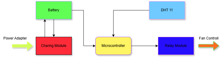
Block Diagram
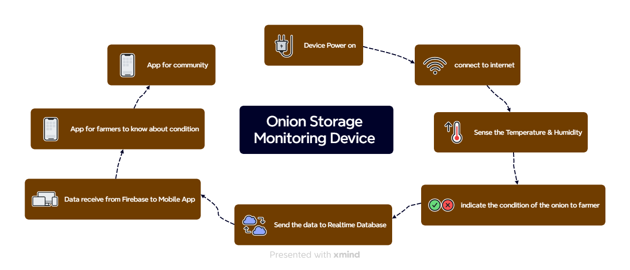
User Flow – Onion Storage Monitoring Device
- Device Power On
The system is turned on using a power adapter or battery. - Connect to Internet
The device connects to Wi-Fi to enable real-time data transfer. - Sense Temperature & Humidity
A sensor (like DHT11) checks the current temperature and humidity in the onion storage area. - Indicate the Condition
If the conditions are not suitable, the system alerts the farmer (e.g., using a buzzer, LED, or mobile notification). - Send Data to Realtime Database
The sensor data is sent to an online database (such as Firebase). - Data Received by Mobile App
The mobile app reads the latest data from the database. - App for Farmers
Farmers can use the app to check current storage conditions and receive alerts. - App for Community
A community dashboard (optional) can give insights to others like co-ops or agricultural officers.
Design Inspiration
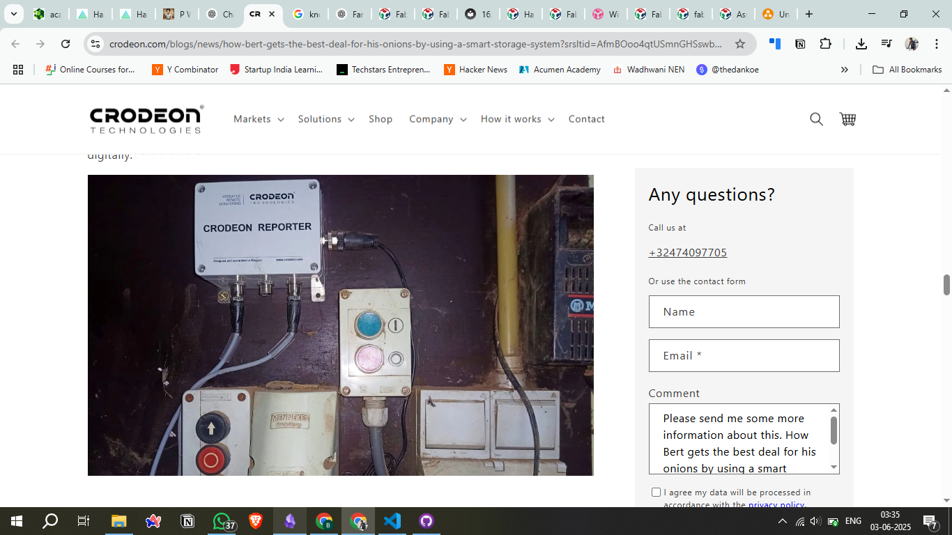
1) Crodeon's Reporter
Crodeon's Reporter is a plug-and-play sensor module designed for remote monitoring of agricultural storage conditions. It measures temperature and humidity inside onion piles and integrates with a cloud dashboard accessible via smartphones or computers.
Learn More: https://www.crodeon.com/
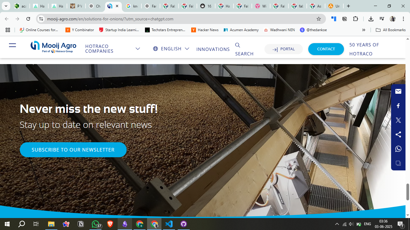
2) Mooij Agro
Mooij Agro offers the Croptimiz-r system, an all-in-one automation solution for onion storage. It continuously monitors and controls temperature, humidity, and ventilation processes.
Learn More: https://www.mooij-agro.com/en/
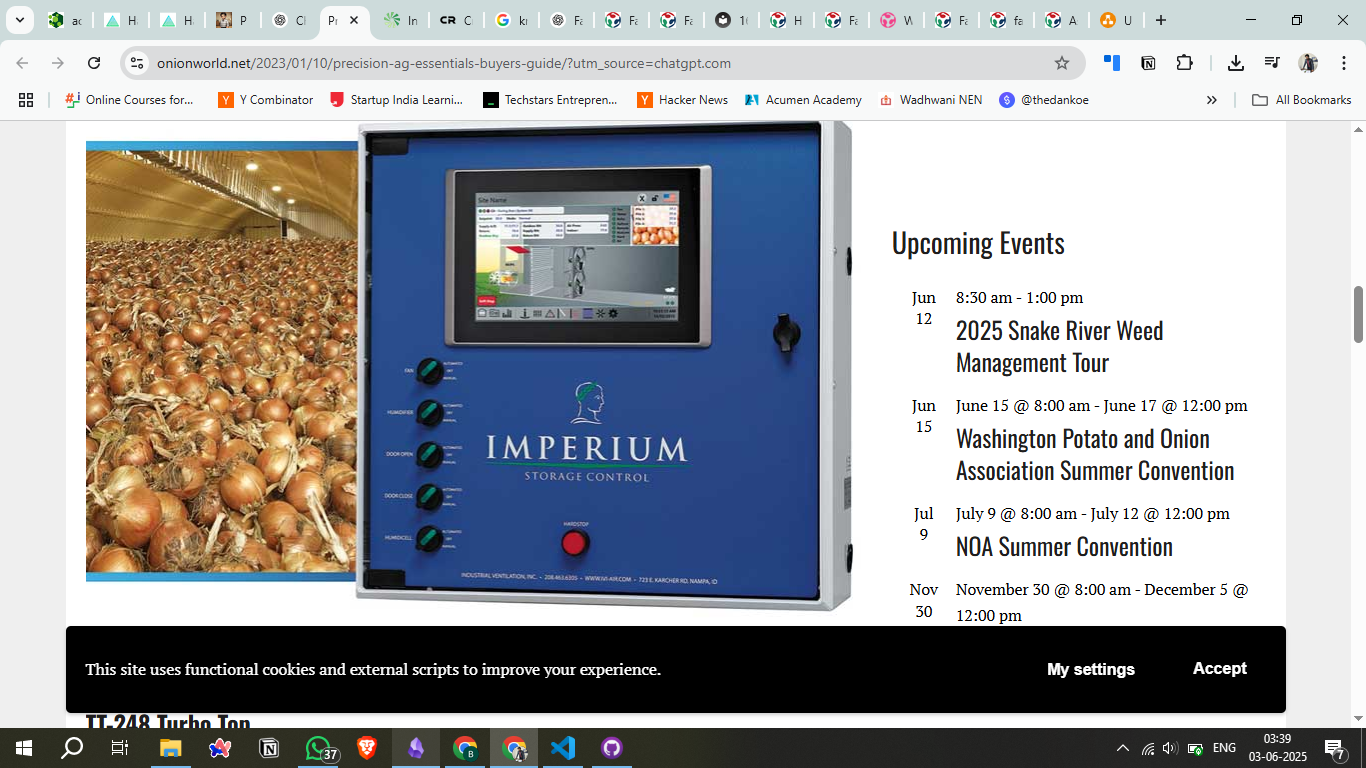
3) IVI's Imperium Control Panel
IVI's Imperium control panel allows precise control over airflow, humidity, and other storage parameters. It includes an app for off-site monitoring and control, making it easier to maintain optimal storage conditions.
Learn More: https://ivi-air.com/
Components
Here's a detailed Component Table based on your image:
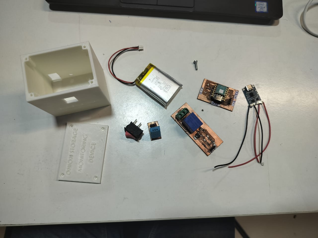
| S. No. | Component Name | Description / Use |
|---|---|---|
| 1 | 3D Printed Enclosure (Box + Lid) | Custom-made casing with "Onion Storage Monitoring Device" label for enclosing circuit |
| 2 | Li-Po Battery | Rechargeable battery, powers the entire circuit |
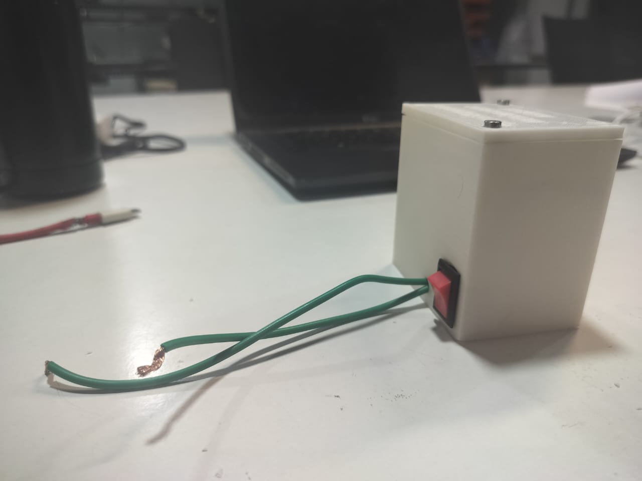
| 3 | Slide Switch | Used to turn the device ON or OFF |
| 4 | DHT11 Sensor | Temperature and humidity sensor |
| 5 | ESP8266 Module on Custom PCB | Microcontroller unit for sensing and communication |
| 6 | Relay Module on Custom PCB | Controls higher power components (e.g., fan or heater) |
| 7 | TP4056 Charging Module | Battery charging module with micro-USB input |
| 8 | Screw | Used to close the enclosure |
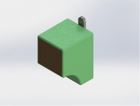
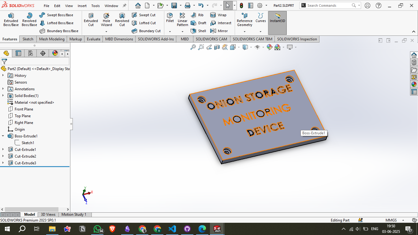
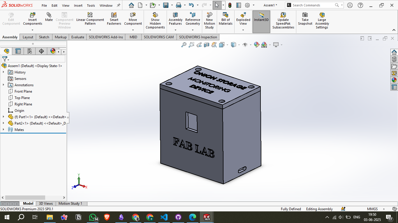
3D Design & Modelling
The enclosure was designed using SolidWorks. It consists of two main parts:
Main Body: A box to house the internal electronics.
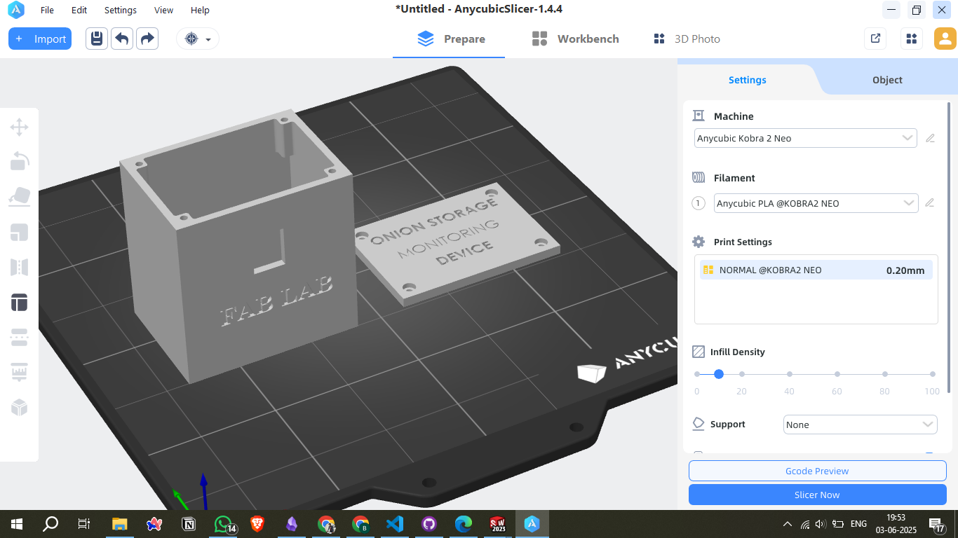
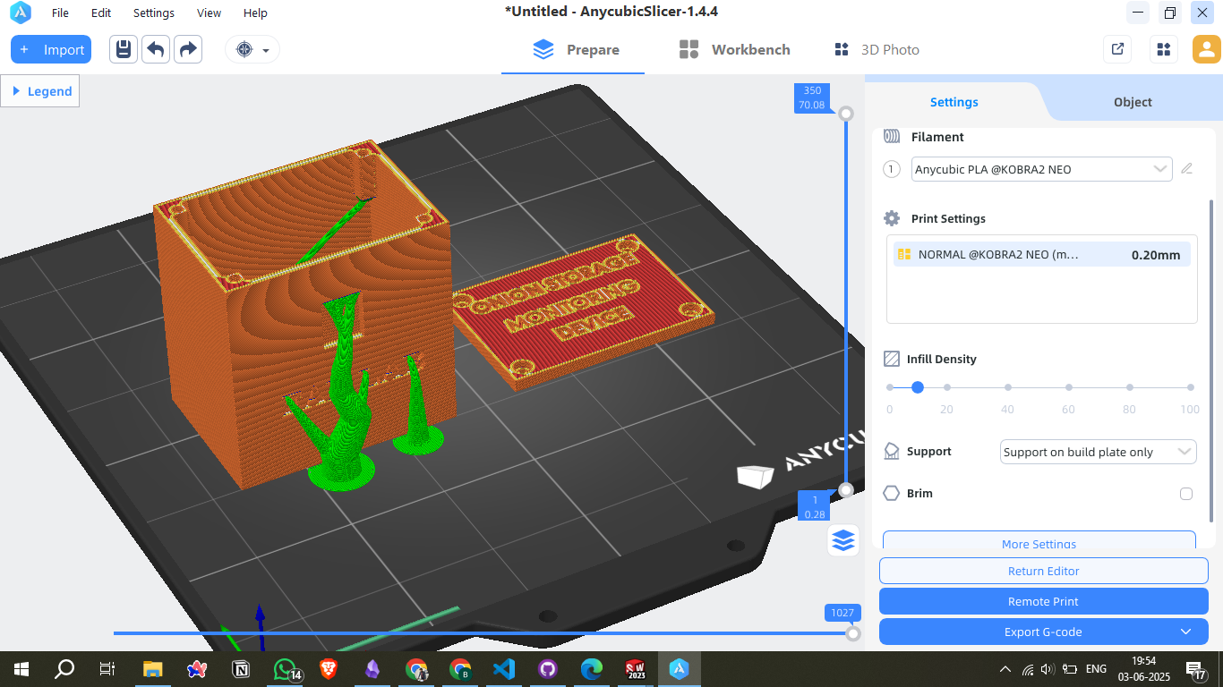
Slicing & 3D Printing
Print Settings
- Layer Height: 0.20 mm (Normal Quality)
- Infill Density: 20%
- Supports: Enabled (on build plate only)
- Print Mode: Exported G-code for remote printing
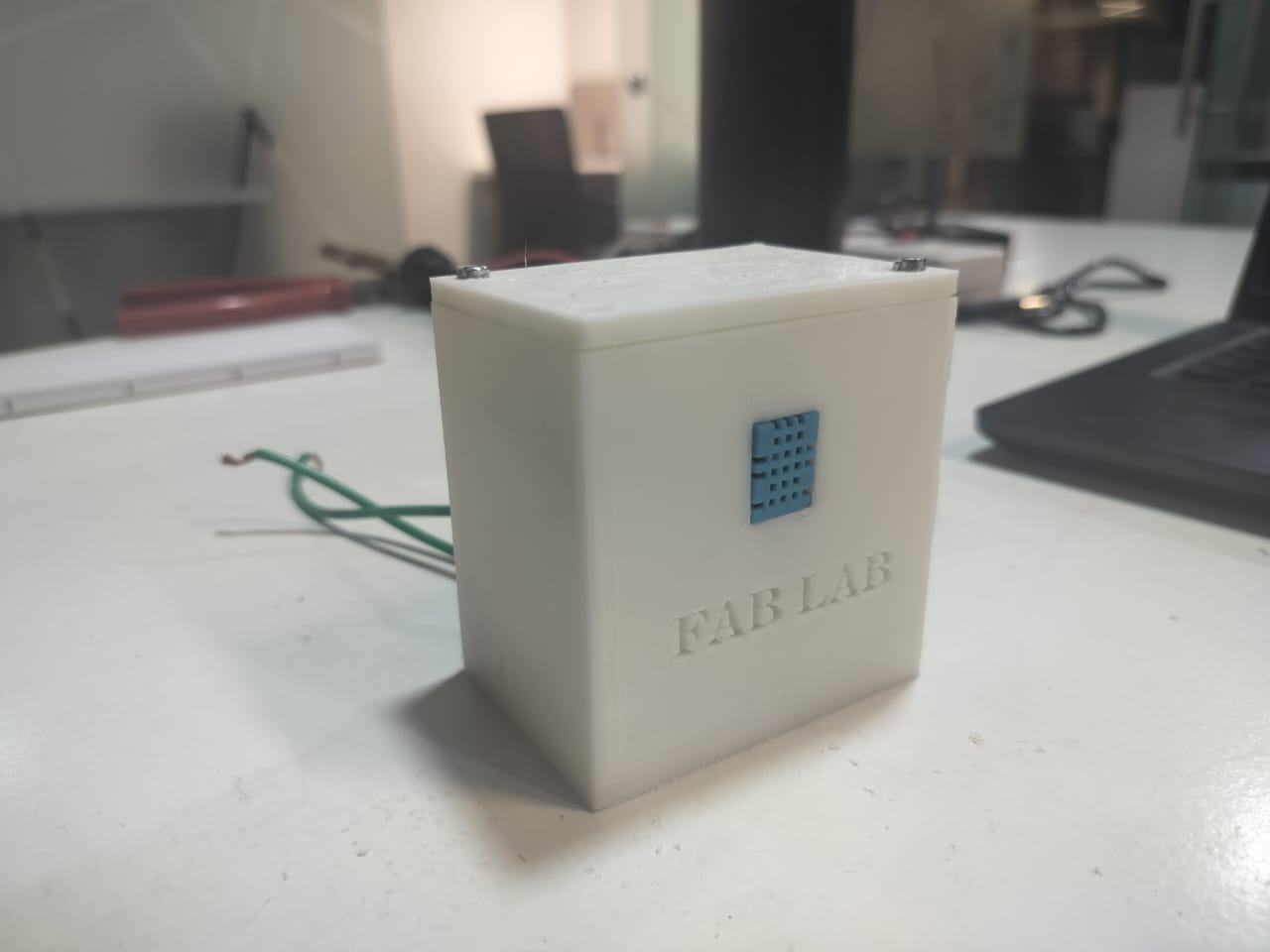
Hero shot
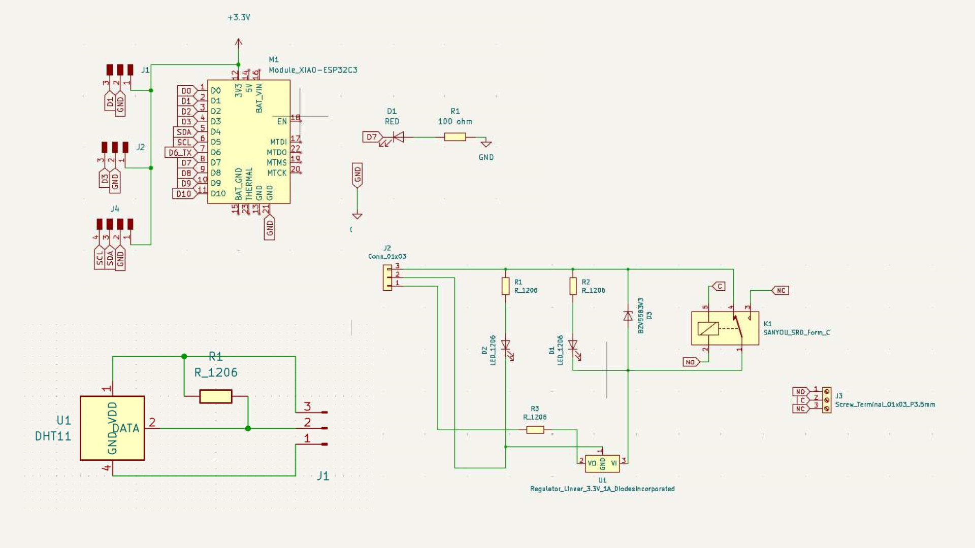
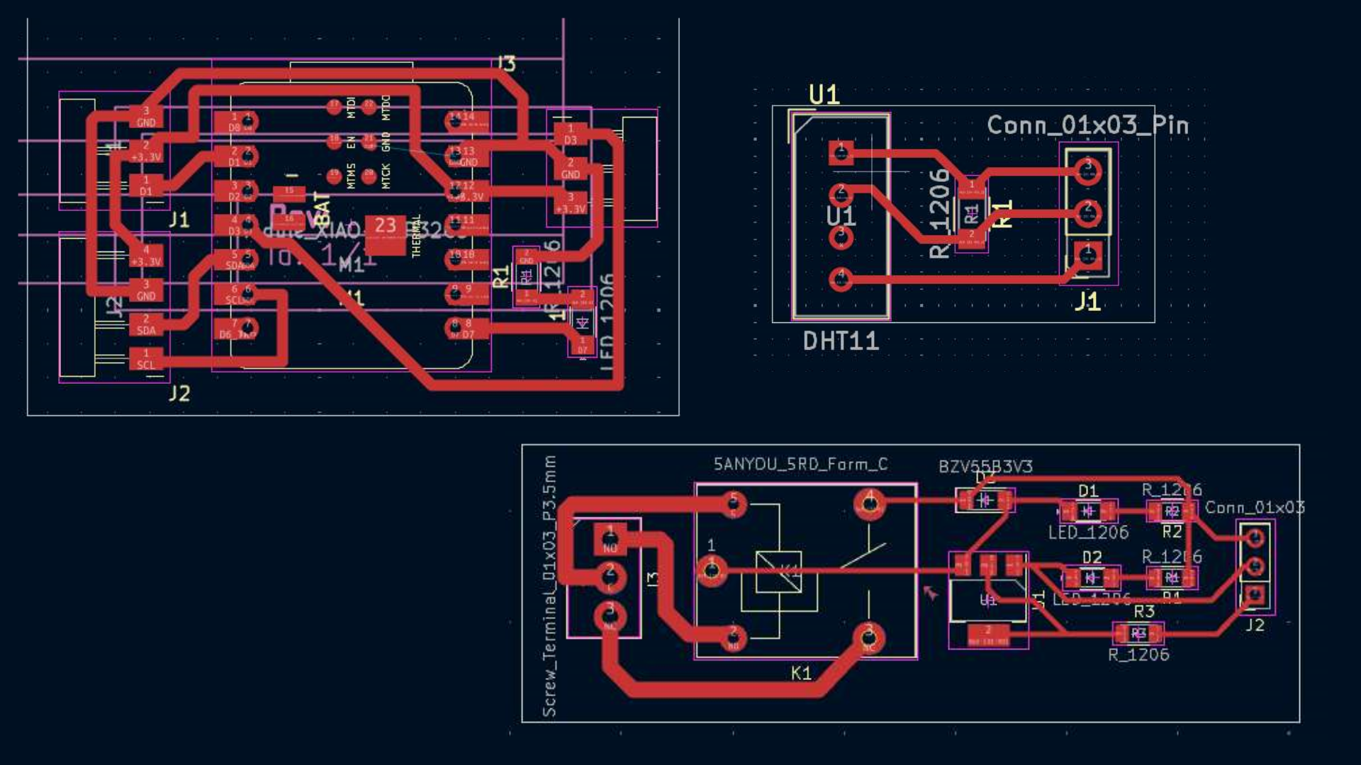
PCB Design
Final Product Design Thought Process
In the final stage of my project, I focused on designing the product with a clear vision. I carefully considered the manufacturing process and decided that most of the components should be 3D printed to ensure precision and ease of assembly. Some parts, however, were better suited for laser cutting due to their flat profiles, while others required the durability and strength provided by wood routing. Based on these considerations, I began designing the product accordingly.