
Week 7
Assignment: Computer-Controlled Machining
Group assignment
The Link of Group assignments.
Individual assignment
- make (design+mill+assemble) something big (~meter-scale)
- extra credit: don't use fasteners or glue
- extra credit: include curved surfaces
Introduction
For this week’s assignment on Computer-Controlled Machining, I chose to design and fabricate an African Birth Chair. I selected this project because it combines cultural significance with practical functionality. The chair is traditionally used during childbirth, symbolizing support and strength. I wanted to explore large-scale CNC machining while also creating a meaningful and usable object that reflects craftsmanship and tradition.
CAD File
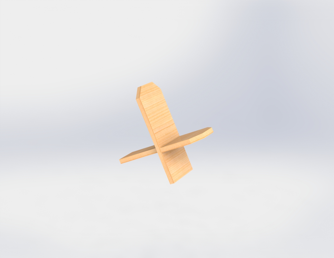
I designed the structure in SolidWorks, focusing on a simple yet strong interlocking system. The design includes two main parts that intersect at 90°, forming a cross-locking structure without the need for glue or screws.
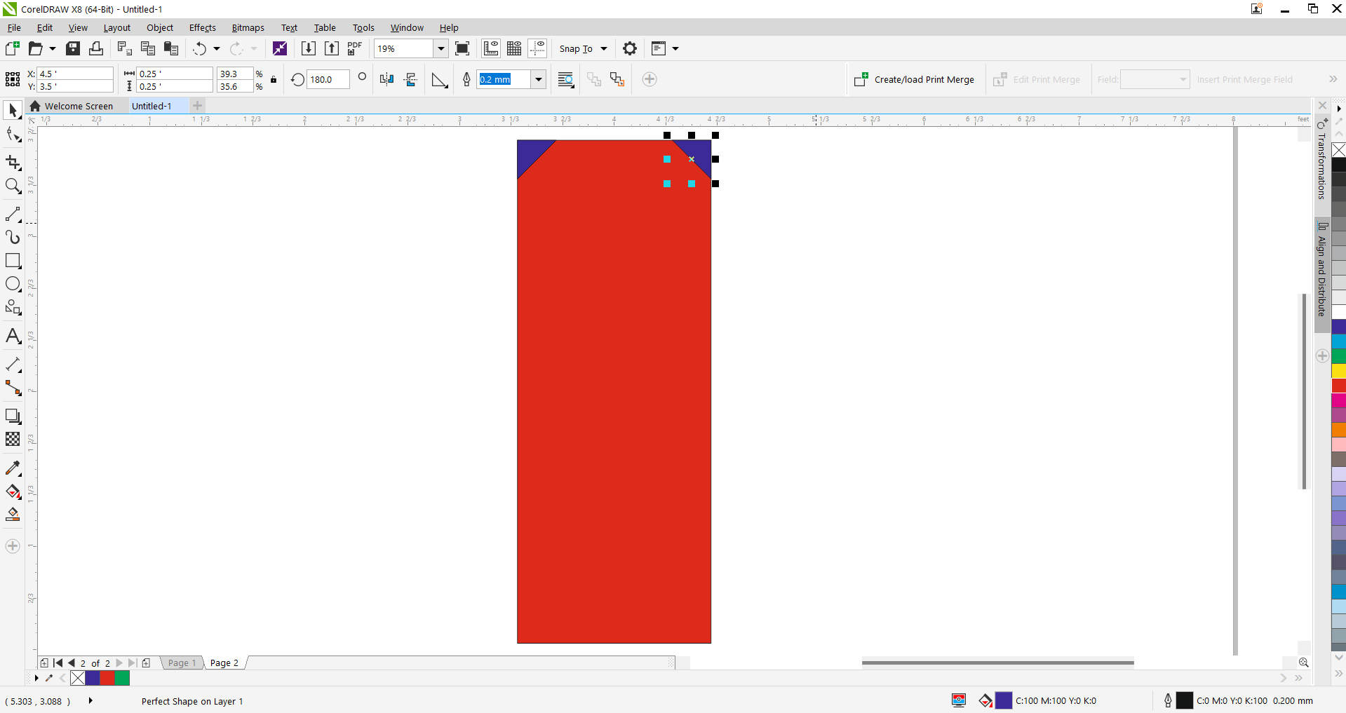
Step 1 - Initial Base Design:
Started with a basic vertical rectangle in CorelDRAW, forming the foundation of the chair's side panel.

Step 2 - Corner Trimming Setup:
Placed triangle shapes at the top corners to trim the edges and add a stylized chamfer effect to the backrest.
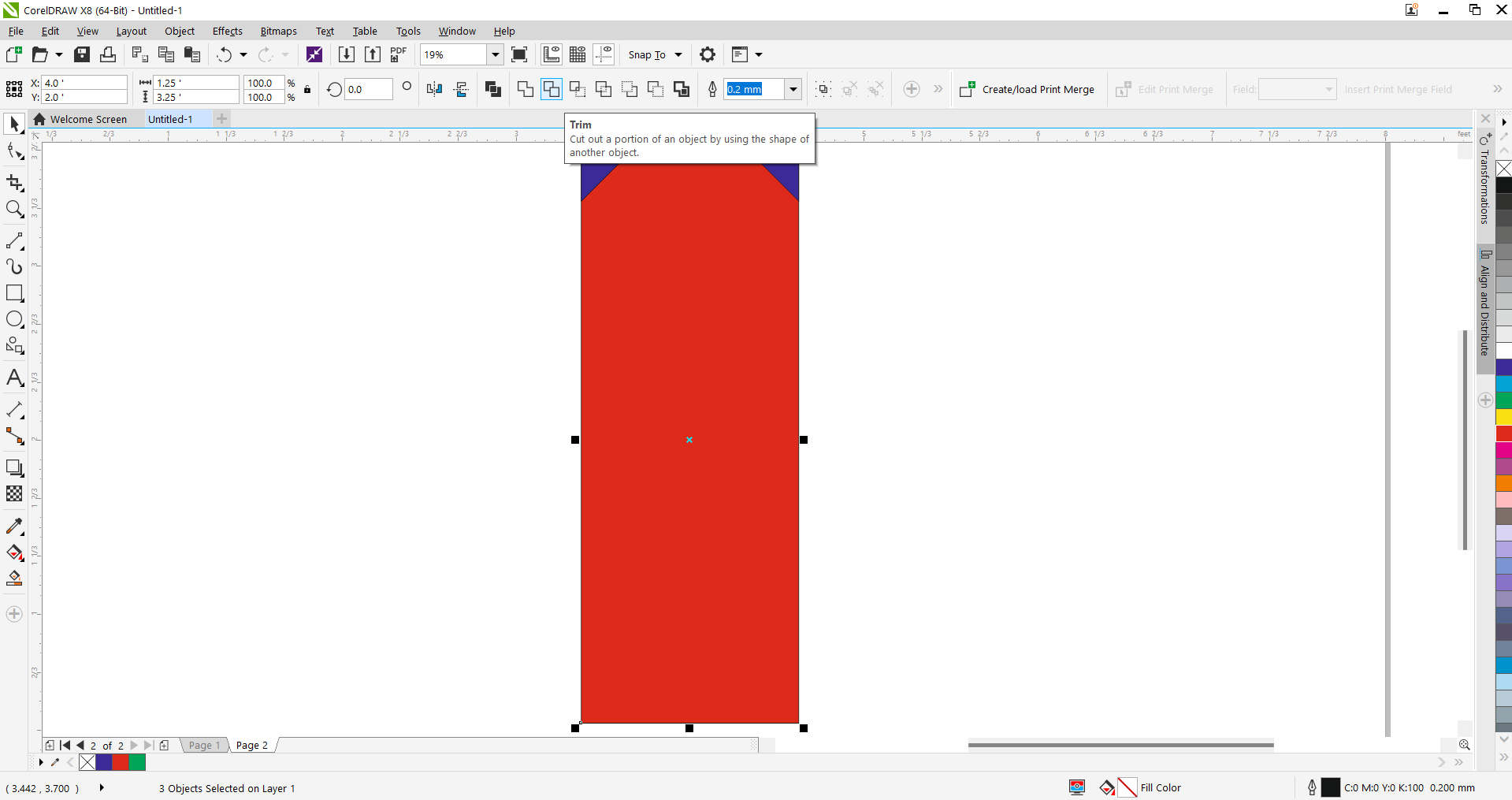
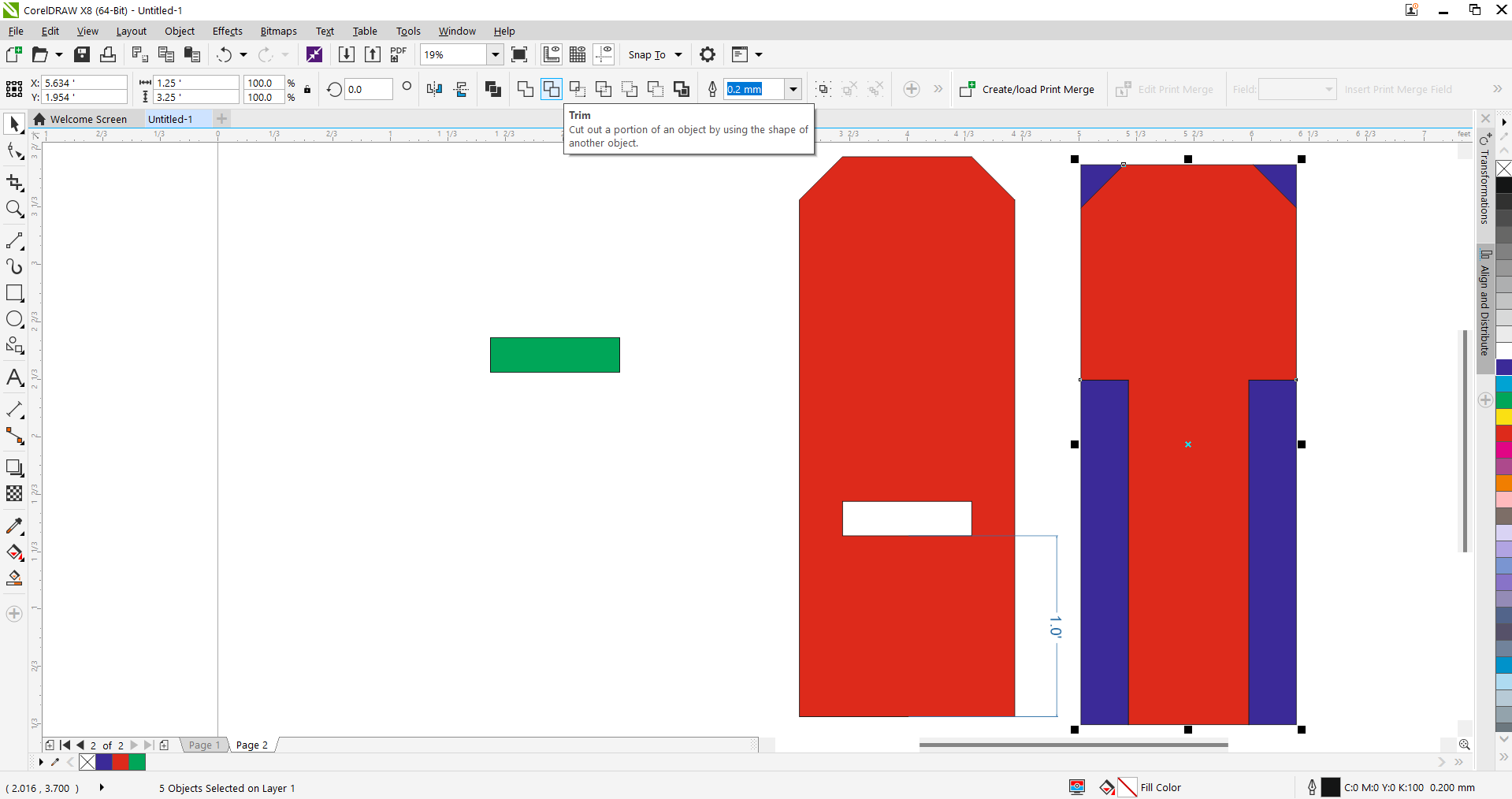
Step 3 - Applying the Trim Tool:
Used CorelDRAW’s Trim feature to cut the corner triangles from the main rectangle, shaping the backrest profile.
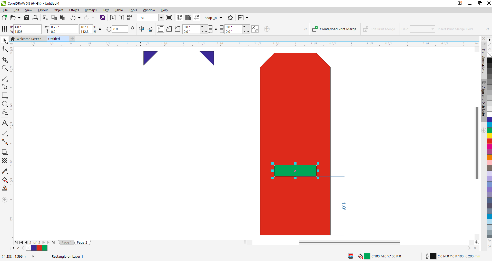
Step 4 - Slot Rectangle Design:
Inserted a small green rectangle to act as the seating slot in the side panel of the chair for fitting the seat.
Step 5 - Full Part Layout:
Duplicated the design and created additional parts including connectors, seat pieces, and support columns.
Step 6 - Final Fitment & Alignment:
Refined the alignment and spacing of the components. The green parts represent slot-fillers and connectors.

Step 7 - Importing Elephant Artwork:
Imported an elephant head image for engraving. This graphic symbolizes strength and cultural roots.
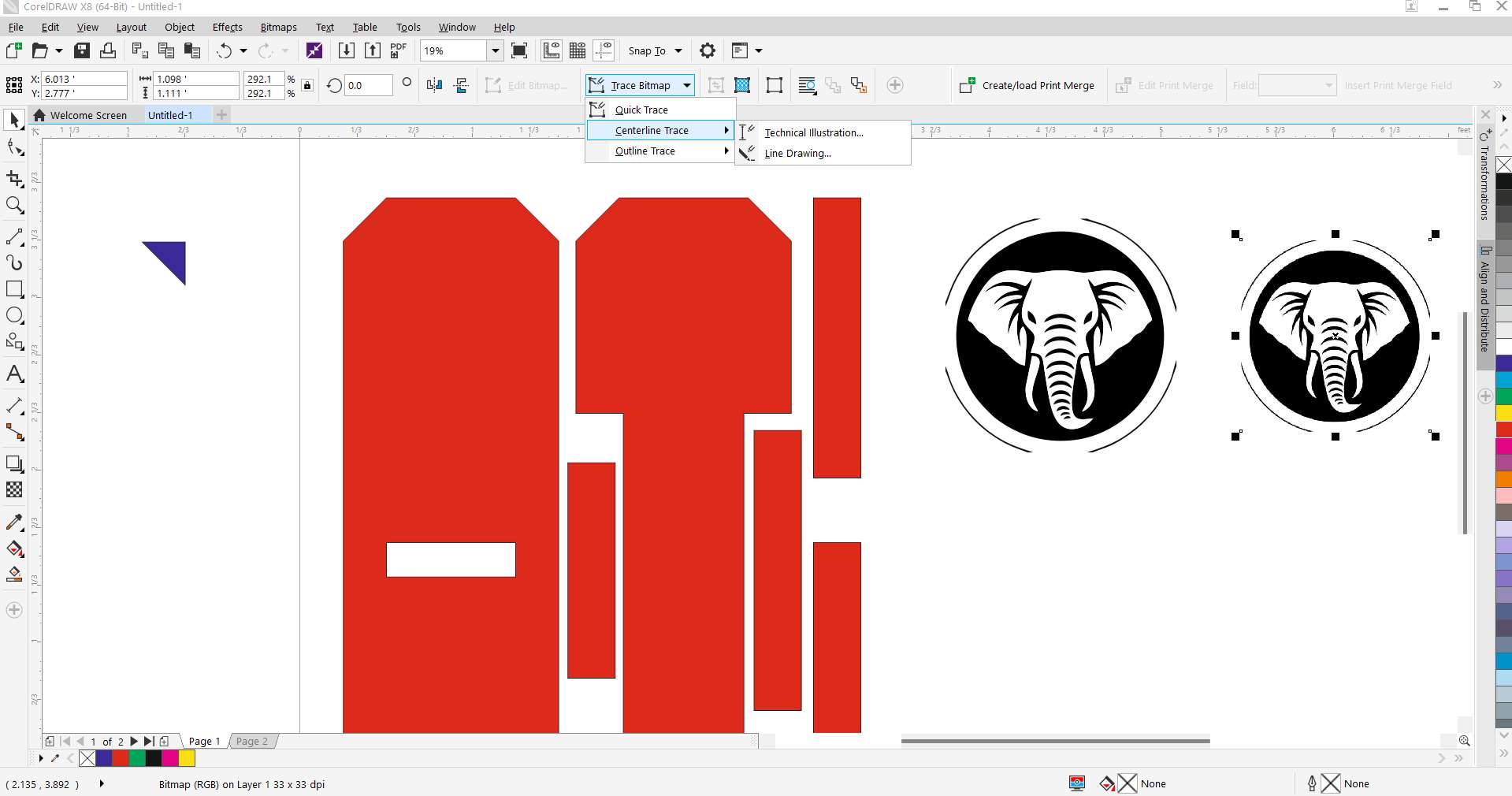
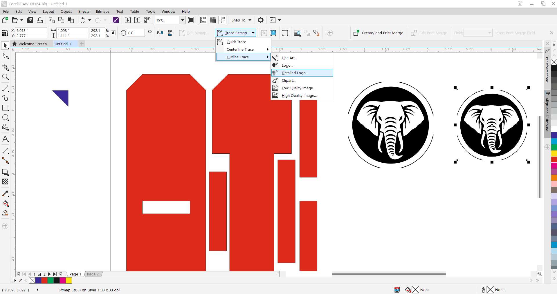
Step 8 - Tracing Bitmap to Vector:
Used the ‘Outline Trace > Detailed Logo’ feature to convert the bitmap image into editable vector lines.
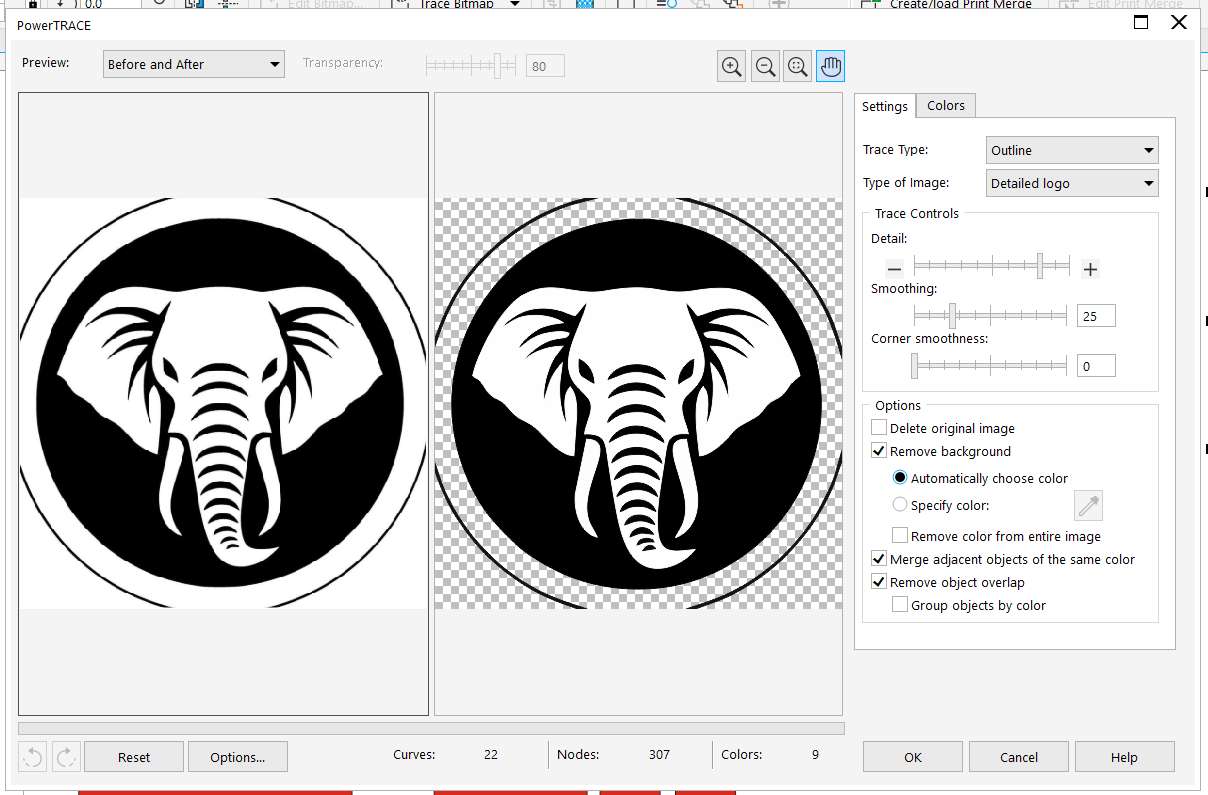
Step 9 - PowerTRACE Cleanup:
Adjusted detail, smoothing, and background removal settings to generate clean vectors from the image.
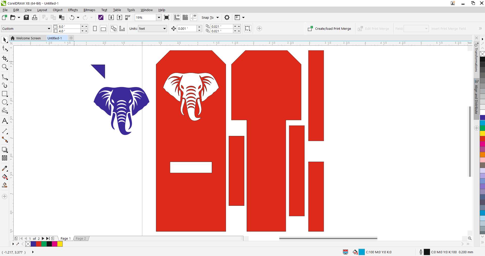
Step 10 - Final Vector Placement:
Placed the traced elephant head vector onto the backrest. This engraving became the centerpiece of the chair.
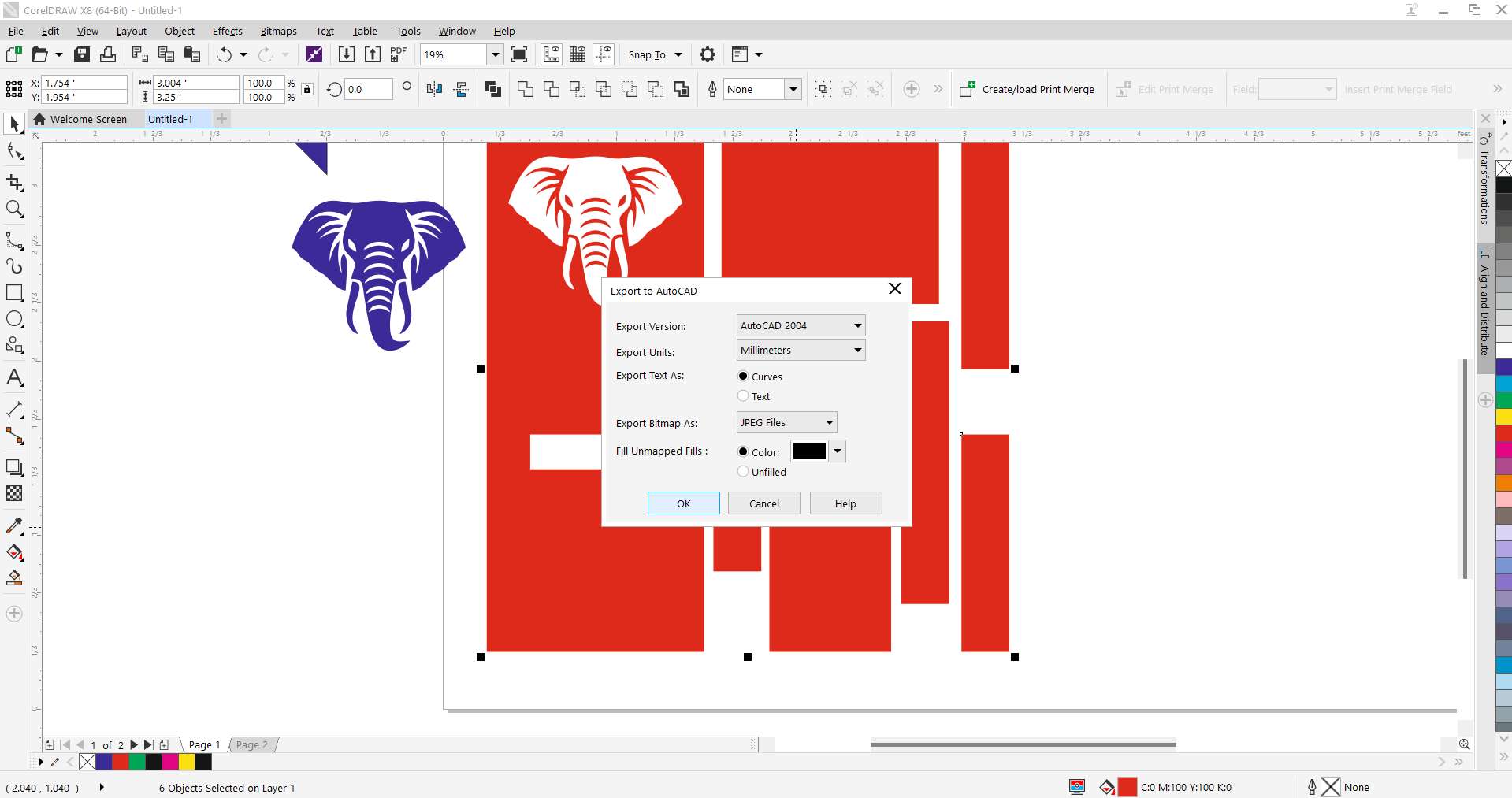
Step 11 - Export to DXF for ArtCAM:
Exported the entire layout as a DXF file with millimeter units to be imported into ArtCAM for toolpath creation.
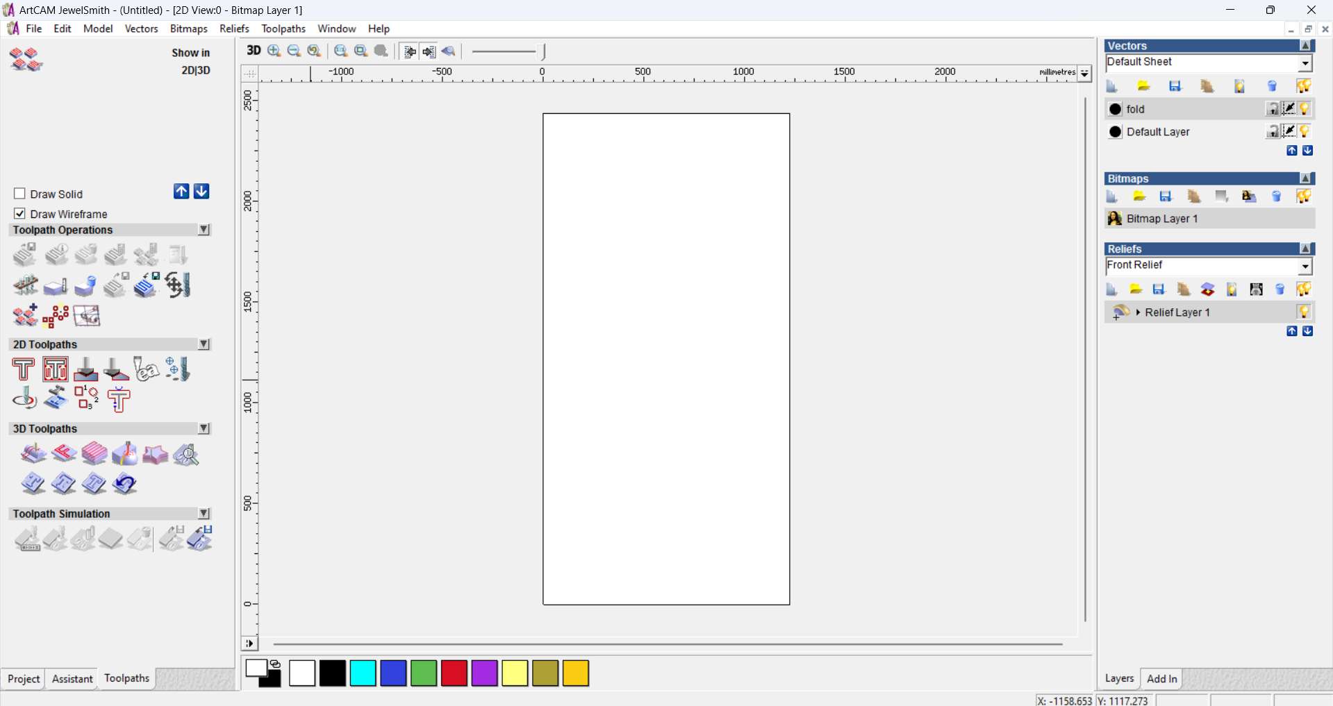
Step 12 - ArtCAM Setup:
Initialized the ArtCAM interface and loaded the DXF layout for 2D and engraving toolpath operations.
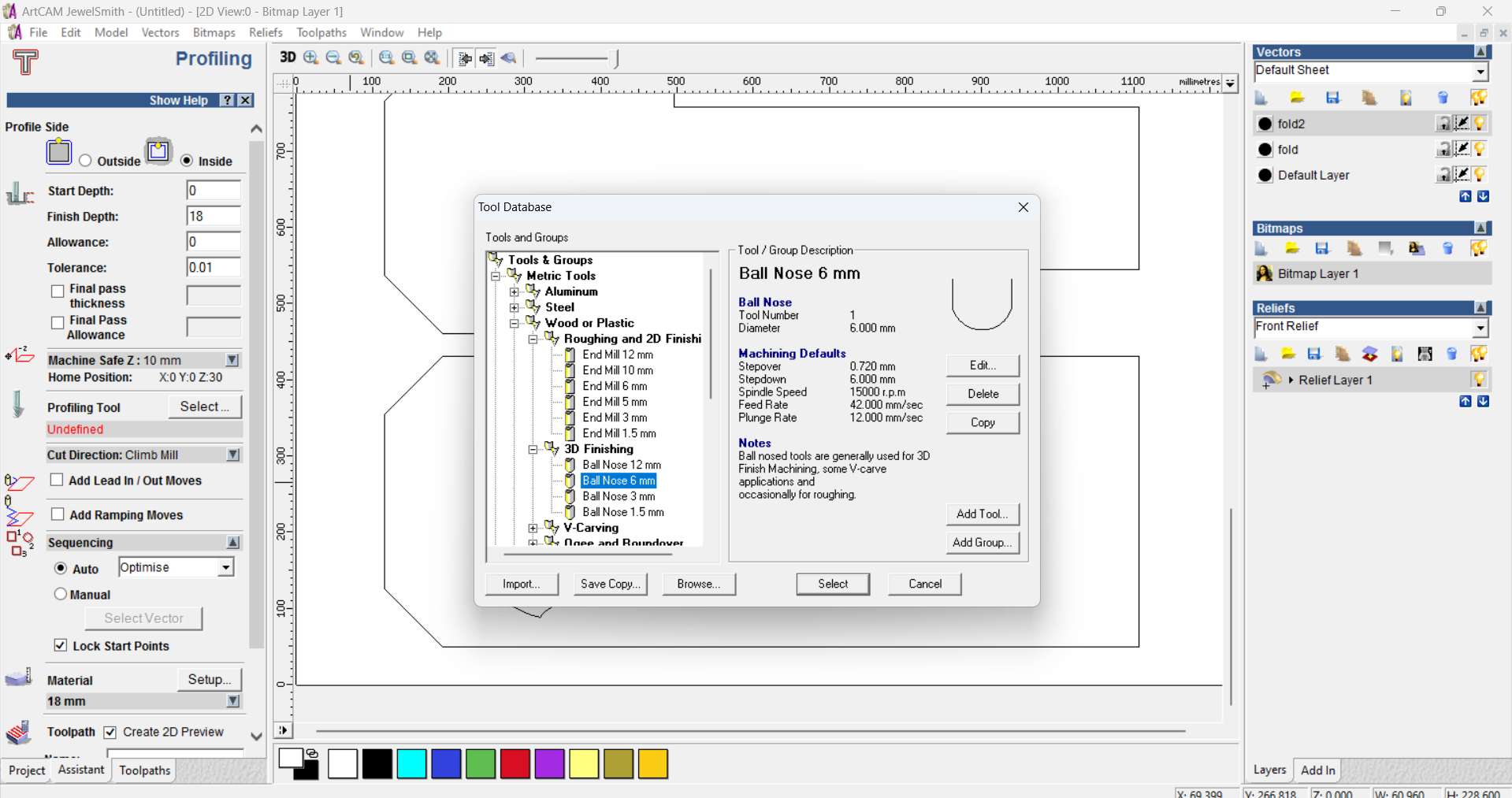
Step 13 - Tool Selection & Parameters:
Selected a 6mm Ball Nose tool with defined stepdown, stepover, and feedrate for both cut and engraving paths.
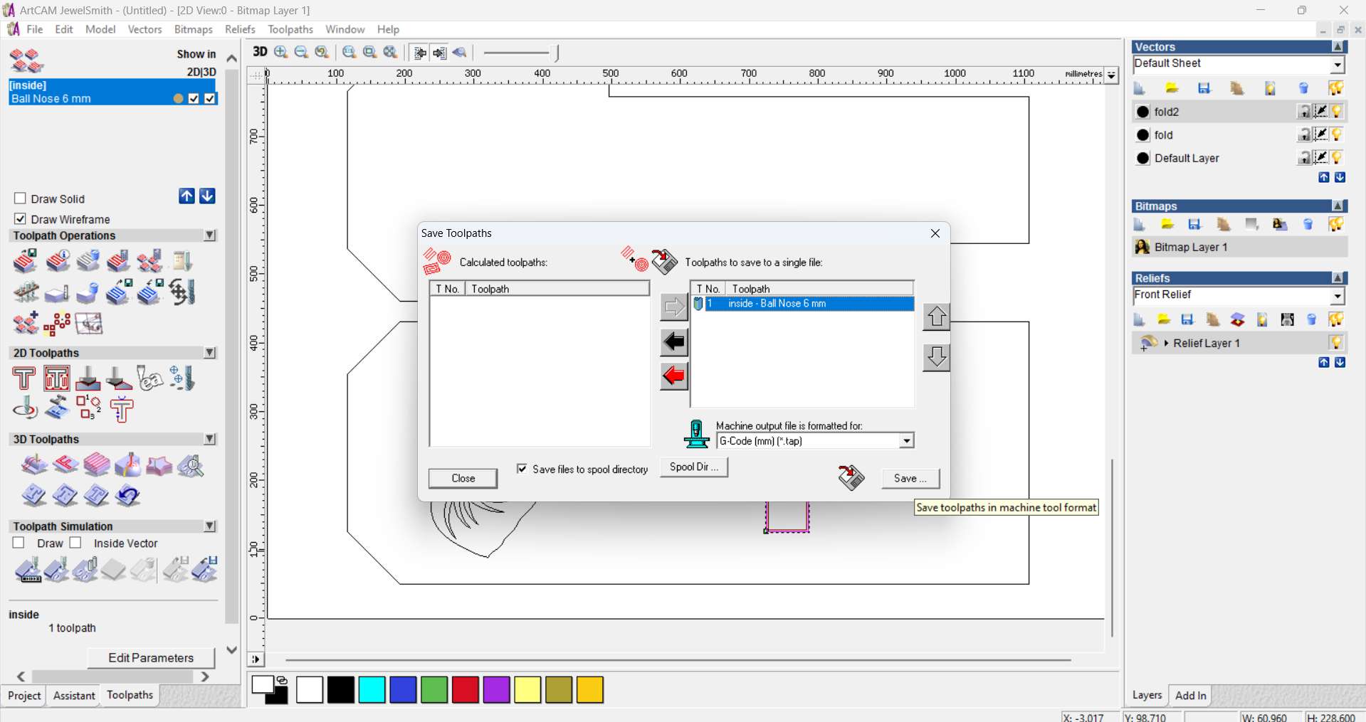
Step 14 - Saving Profile Toolpath:
Generated and saved the profile cutting path using inside cut method and enabled lead-in/out moves.
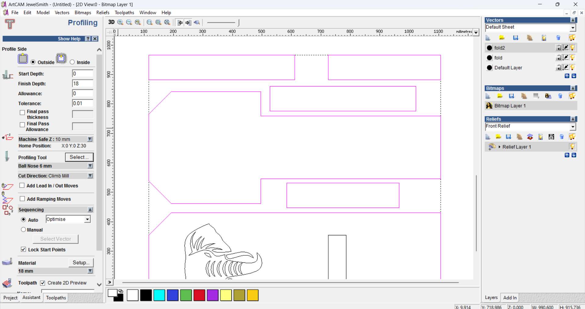
Step 15 - Toolpath Preview in ArtCAM:
Previewed the full toolpath outline including the profile cut and the position of the engraved elephant vector.
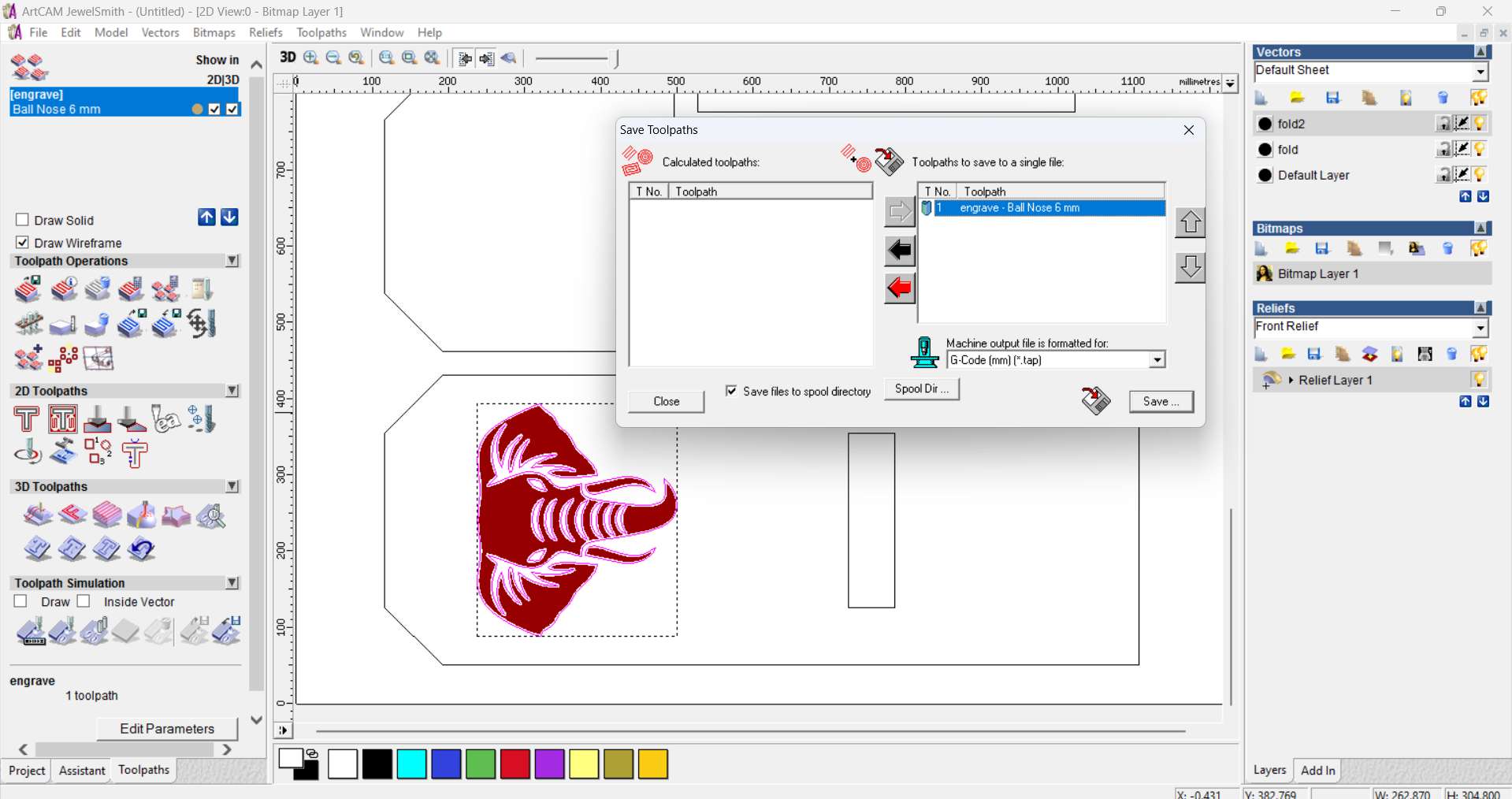
Step 16 - Saving Engraving Path:
Saved a separate G-code toolpath for the elephant head engraving using the same 6mm Ball Nose bit.
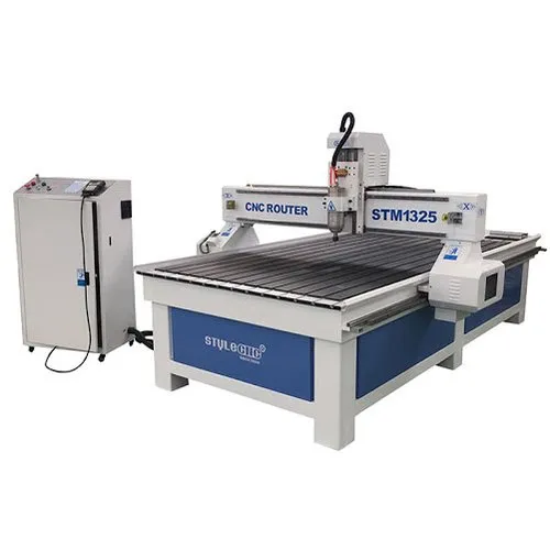
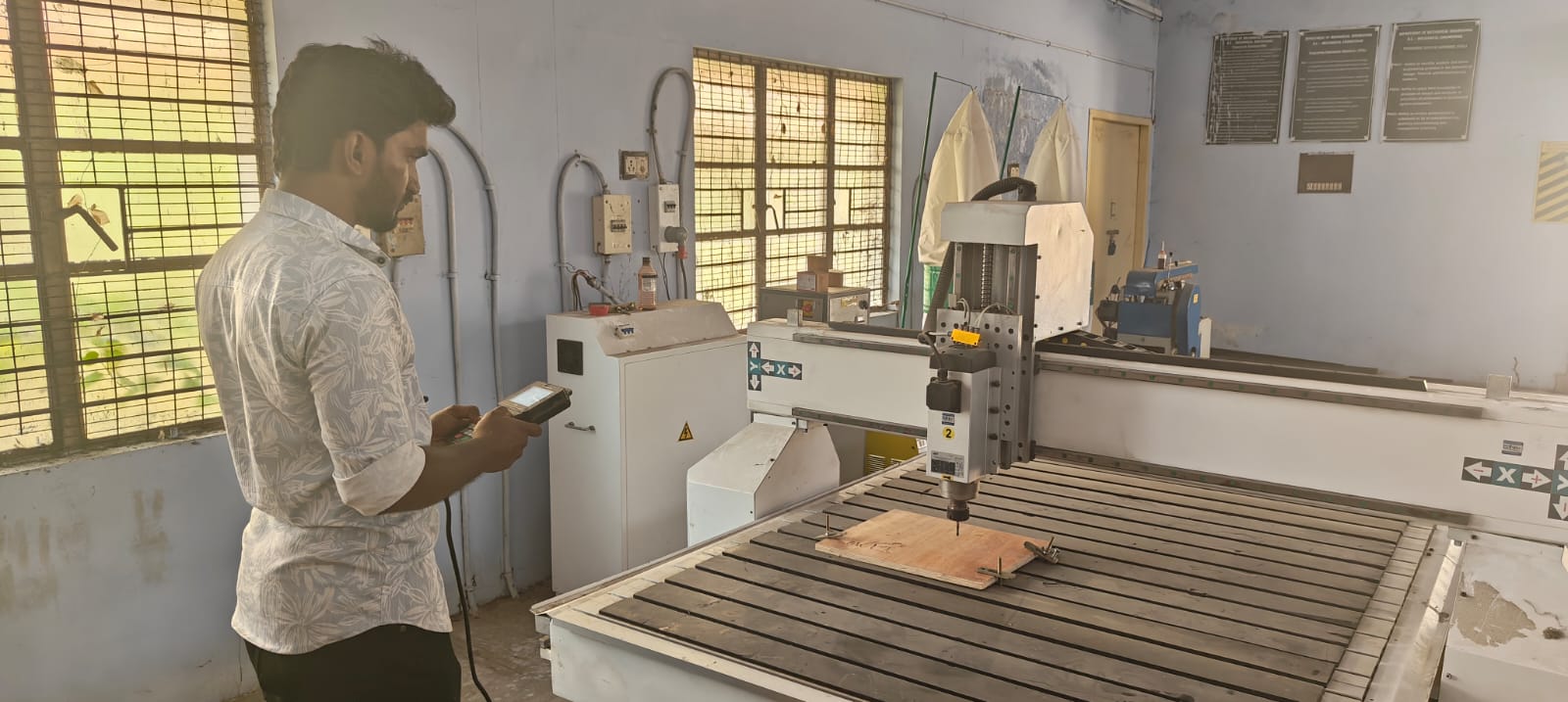
Step 17 - Machine Details & Safety Precautions
For this assignment, I used the STM 1325 CNC router, a robust and precise machine suitable for large-format cutting tasks.
Safety Precautions Followed:
PPE Usage: I wore safety goggles, ear plugs, and a dust mask to protect against flying debris, loud noise, and fine dust particles.
Emergency Preparedness: Familiarized myself with the emergency stop button and the main power switch before starting.
Workspace Check: Cleared the work area of any loose tools or obstructions.
Material Clamping: Ensured the plywood sheet was tightly secured to the bed with clamps to prevent movement during cutting.
Bit Safety: Confirmed the correct tool bit was installed and firmly tightened in the spindle.
Step 18 - Machine Setup Steps (STM 1325)
1. Design Preparation:
Created the design in Fusion 360 (or mention your software).
Exported it as a DXF file and imported into ArtCAM for toolpath generation.
2. Material Used:
12mm plywood sheet chosen for its strength and wide availability.
3. Toolpath Creation in ArtCAM:
Generated profile and pocket toolpaths with appropriate depth and clearance.
Added dogbone fillets for joints where necessary.
4. Machine Zeroing:
Set the X, Y, Z zero points at the corner of the material using the machine's control panel.
5. Machining Process:
Monitored the cutting process carefully.
Paused midway to clear dust and check alignment.
6. Post-Cutting Tasks:
Removed the finished parts from the board.
Cleaned up the tabs, sanded edges, and started the assembly process.
Working Image
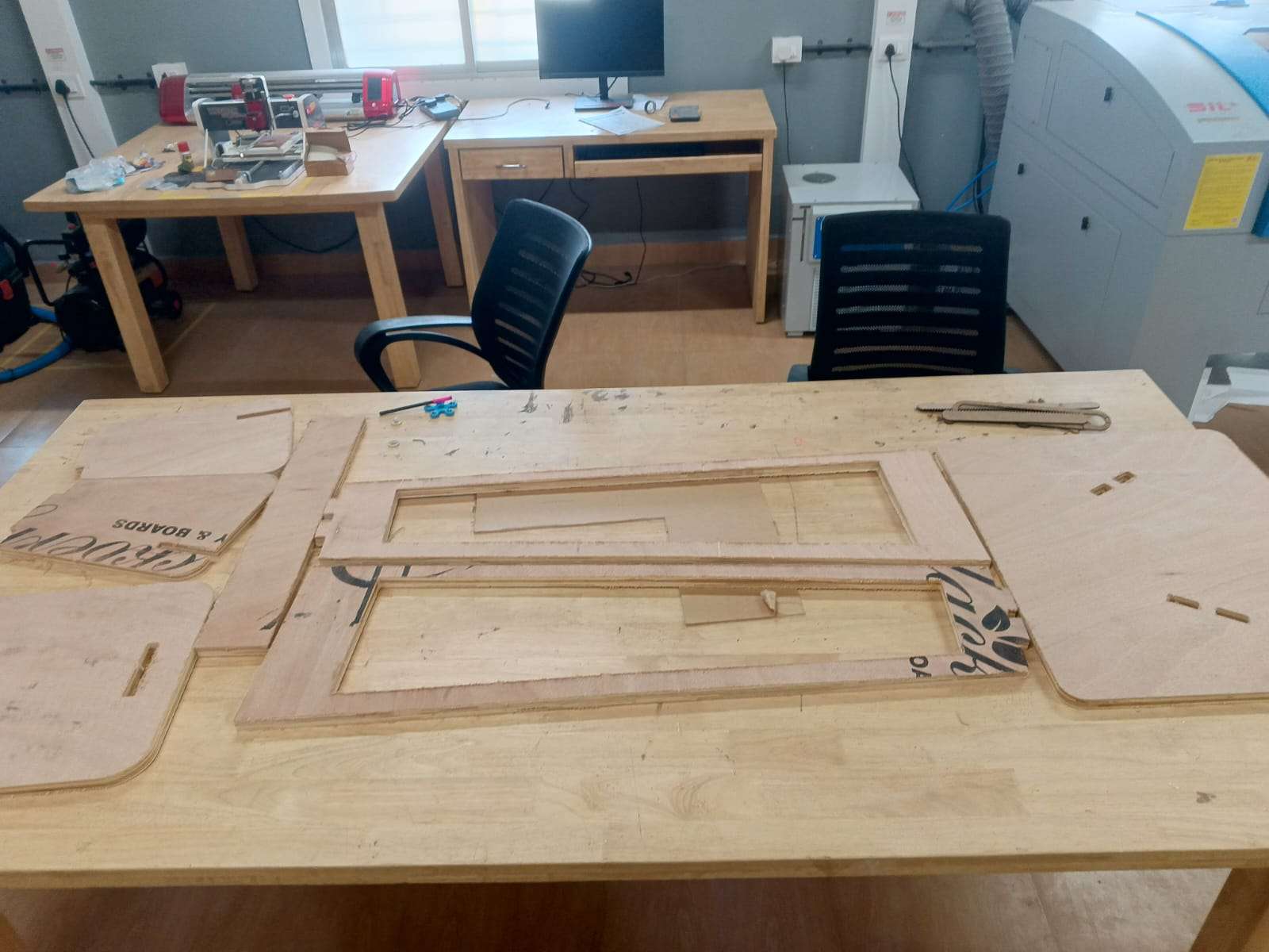
Step 19 - CNC Milled Components:
Cut plywood parts ready after CNC milling. This includes the backrest, base, seat, and support elements.
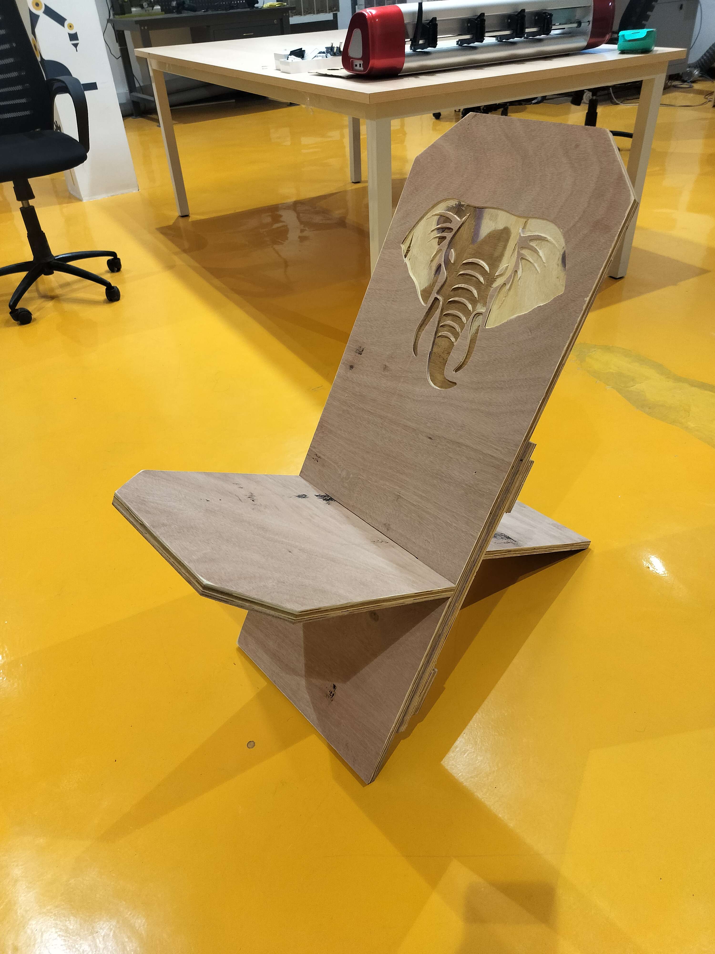
Step 20 - Fully Assembled Chair:
Assembled the African Birth Chair with a slot-fit design. The engraved elephant head adds cultural depth.
Step 21 - User Testing:
The final chair was successfully tested by sitting. It proved to be structurally sound and comfortable.
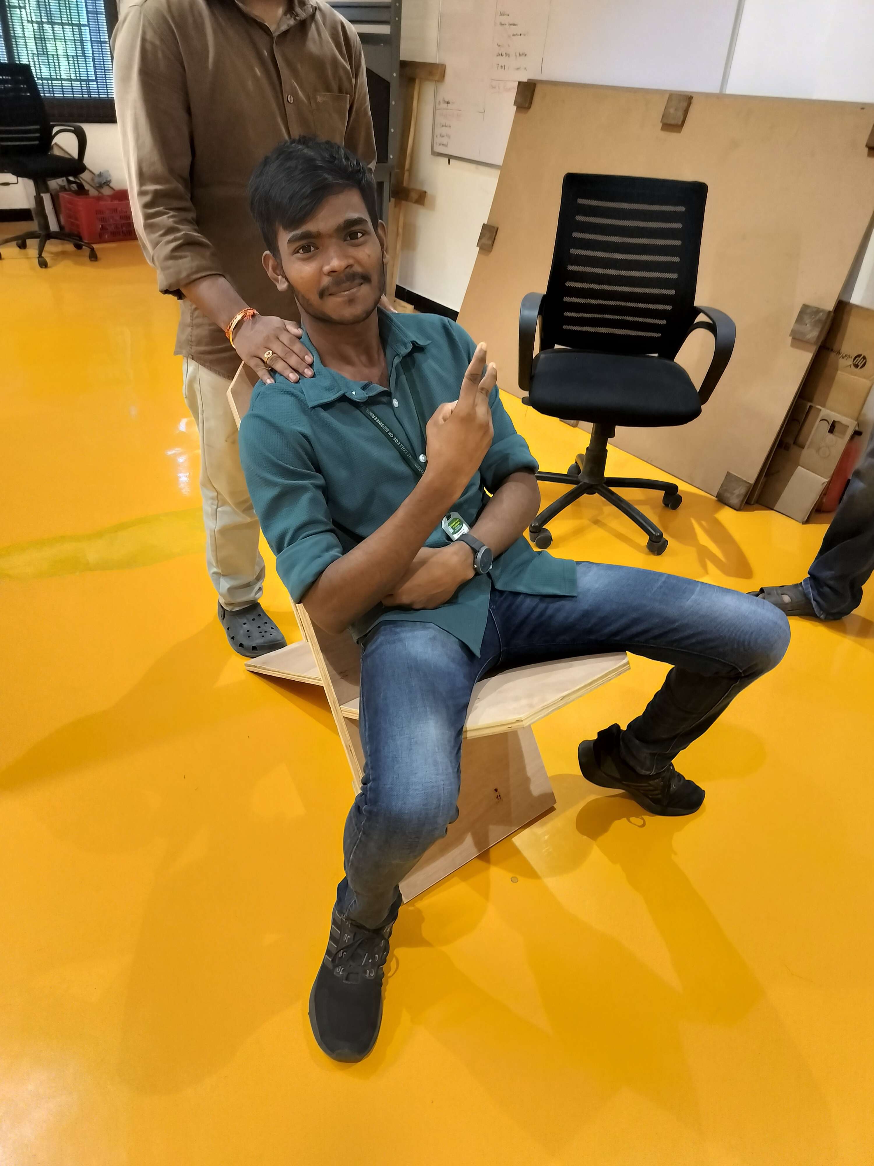
Table of Contents
- 1. Initial Base Design
- 2. Corner Trimming Setup
- 3. Applying the Trim Tool
- 4. Slot Rectangle Design
- 5. Full Part Layout
- 6. Final Fitment & Alignment
- 7. Importing Elephant Artwork
- 8. Tracing Bitmap to Vector
- 9. PowerTRACE Cleanup
- 10. Final Vector Placement
- 11. Export to DXF for ArtCAM
- 12. ArtCAM Setup
- 13. Tool Selection & Parameters
- 14. Saving Profile Toolpath
- 15. Toolpath Preview in ArtCAM
- 16. Saving Engraving Path
- 17. CNC Milled Components
- 18. Fully Assembled Chair
- 19. User Testing