
Week 5
Assignment: 3D Scanning and Printing
Group assignment
test the design rules for your 3D printer(s).
The Link of Group assignments.
Individual assignment
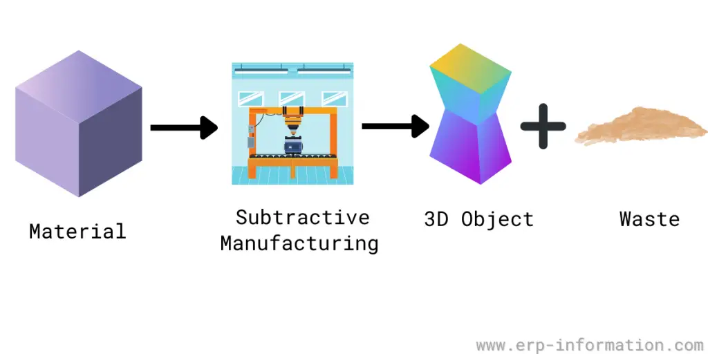
- design and 3D print an object (small, few cm3, limited by printer time) that could not be made subtractively
- 3D scan an object (and optionally print it)
Introduction
Individual assignment
For this assignment, I designed and 3D printed a gear that could not be manufactured through subtractive methods due to its intricate geometry and parameter-driven adaptability. The object was designed using SolidWorks and fabricated using a Anycubic Kobra 2 neo 3D printer.
Various Manufacturing Processes Explored
In this assignment, I explored both additive and subtractive manufacturing processes:
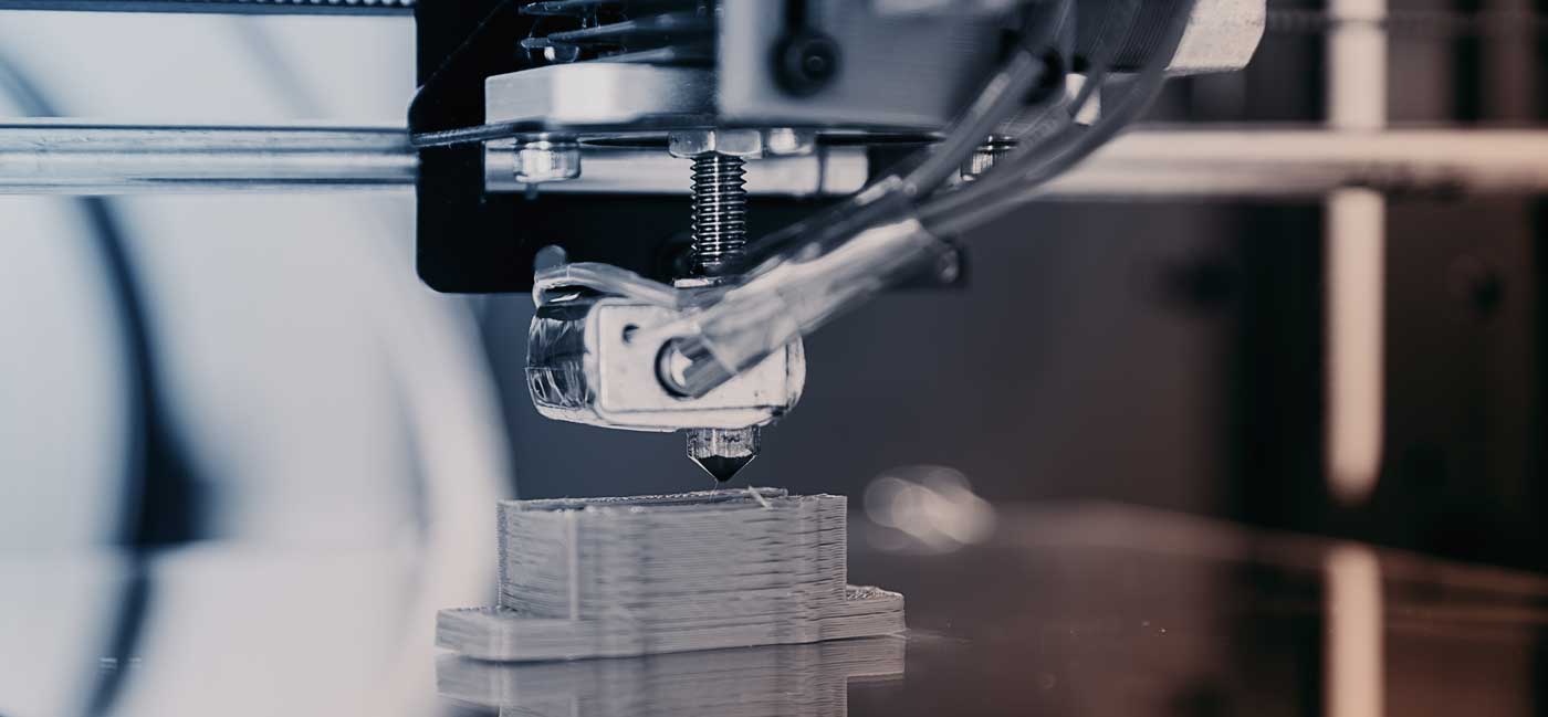
Additive Manufacturing (3D Printing): Utilized the Anycubic Kobra 2 Neo FDM printer to fabricate a complex gear design. This process builds objects layer by layer, allowing for intricate geometries that are challenging to achieve with traditional methods.
Subtractive Manufacturing (3D Scanning): Employed the Kiri Engine app to scan a physical toy, capturing its geometry by removing material from a digital model to create a 3D representation. This method is beneficial for reverse engineering and replicating existing objects.
Advantages and Limitations of FDM 3D Printing
Advantages:
Design Freedom and Complexity Handling: FDM allows fabrication of geometries that are difficult or impossible with traditional subtractive manufacturing (e.g., lattice structures, internal channels). Supports parametric and organic design optimized through topology optimization or generative design tools.
Rapid Prototyping and Iteration Cycles: Digital-to-physical transition is fast—STL files can be generated from CAD models and directly printed without tooling. Enables iterative design loops in short timeframes (fail fast, learn fast approach).
Material and Cost Efficiency: Additive process minimizes material wastage. Economical for low-volume and custom parts—no need for molds or jigs.
Decentralized Manufacturing: Designs can be distributed digitally and fabricated locally using desktop 3D printers, promoting just-in-time (JIT) and localized production.
Limitations:
Mechanical and Structural Weakness: Parts exhibit anisotropic mechanical properties—Z-axis is significantly weaker due to interlayer adhesion. Not suitable for high-load or high-temperature applications unless specialized materials are used (e.g., PC, Nylon, CF composites).
Dimensional Accuracy and Tolerance Stack-up: Shrinkage, warping, and layer misalignment can lead to tolerance errors (typically ±0.1–0.3 mm depending on the printer). Post-processing or calibration needed for precise mechanical fits.
Surface Finish and Aesthetic Limitations: Visible layer lines and support marks often require sanding or chemical smoothing (e.g., acetone vapor for ABS). Resolution limited by nozzle diameter and layer height (typically 0.1 mm to 0.3 mm per layer).
Material Constraints and Compatibility: Standard FDM materials are thermoplastics like PLA, ABS, PETG; advanced materials require high-temp extruders or heated chambers. Hygroscopic materials like Nylon degrade in quality if not stored properly.
Build Volume Constraints: Limited by printer's physical volume—requires splitting large parts and mechanical joining after print.
Application of Design Methods and Production Processes
1. CAD Modeling with DfAM (Design for Additive Manufacturing)
The part was designed using Fusion 360 in parametric mode, allowing constraint-based modeling and dimension-driven features.
DfAM principles applied: Avoided unsupported overhangs > 45° to reduce support material. Ensured minimum wall thickness ≥ 0.8 mm for structural rigidity. Used chamfers instead of fillets where possible for print stability. Integrated self-aligning features for assemblies.
2. Slicing and G-code Generation
Slicing software used: Anycubic
Key slicing settings: Layer height: 0.2 mm (standard resolution). Infill density: 20% Grid pattern (functional strength with time efficiency). Shell thickness: 1.2 mm (3 perimeters with 0.4 mm nozzle). Support material: Enabled for overhangs > 60°. Print speed: 50 mm/s, Retraction: 6 mm @ 25 mm/s
G-code was reviewed in layer-by-layer preview mode for toolpath optimization.
3. Printer Setup and Fabrication
Machine used: Anycubic kobra neo 2 (Bowden-style FDM printer)
Material: PLA 1.75 mm, extruded at 200°C with 60°C bed temperature
Calibration: Manual bed leveling using feeler gauge at four corners. Extrusion tested using 100 mm extrusion check to validate E-steps.
The print was monitored for initial layer adhesion using skirt + brim strategy and Z-offset adjusted accordingly.
4. Post-Processing
Support removal was done manually with flush cutters and tweezers. Surface smoothed with 400-grit to 1000-grit sandpaper. Part tolerance tested using calipers; adjusted CAD tolerances for clearance fits (gap of 0.25 mm worked best for sliding fit).
5. Validation and Learnings
Final print closely matched CAD dimensions (within ±0.2 mm), validating slicing and design parameters. Observed minor warping in corner areas due to uneven cooling—next iteration includes chamfered base and lower bed temp.
3D Printer Used in the Lab
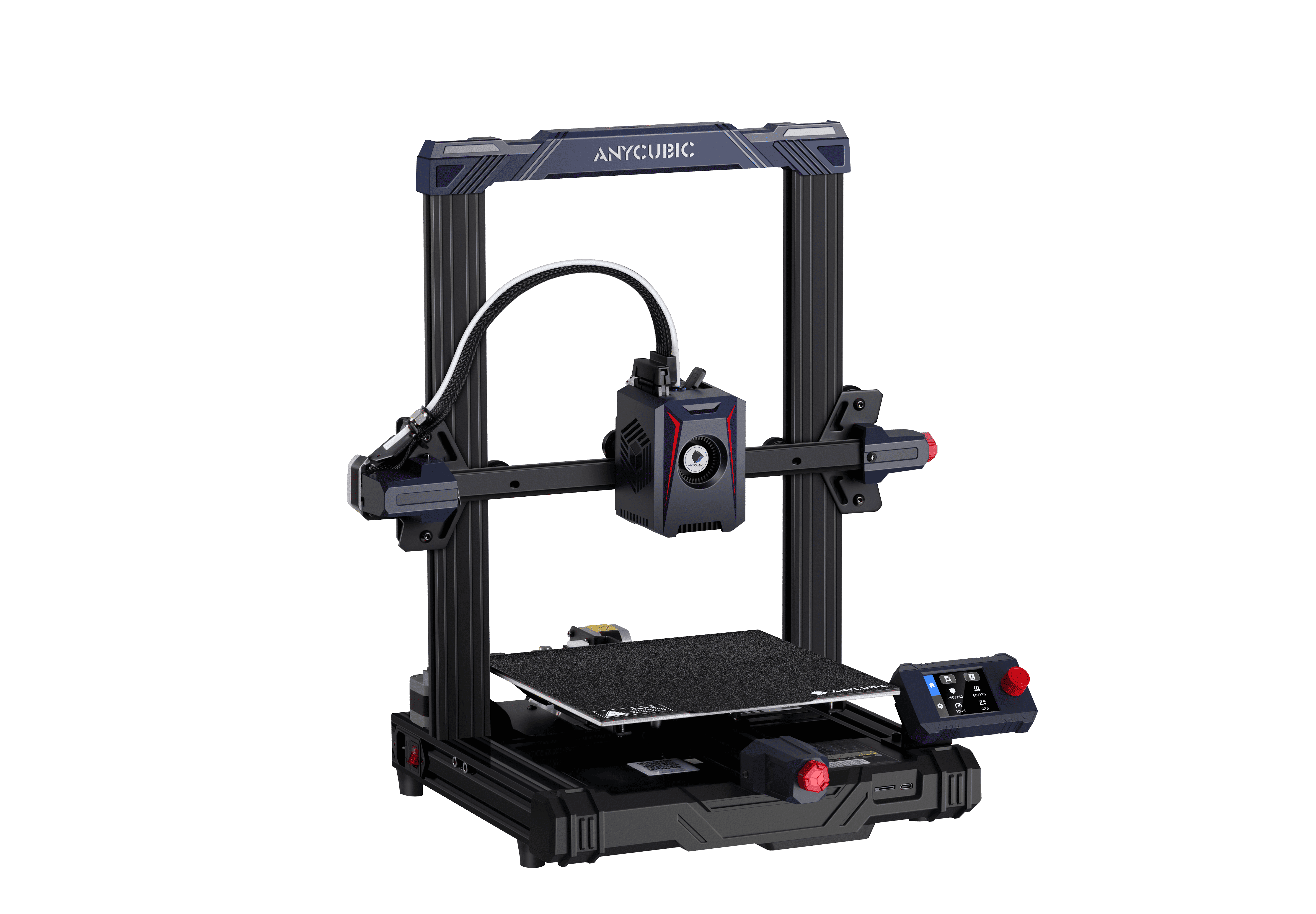
The Anycubic Kobra 2 Neo FDM 3D printer was utilized for this assignment. Key features include:
Printing Technology: Fused Deposition Modeling (FDM)
Build Volume: 220 x 220 x 250 mm
Layer Resolution: 0.1 – 0.4 mm
Nozzle Diameter: 0.4 mm
Filament Compatibility: PLA, ABS, PETG, and TPU
This printer offers user-friendly features such as automatic bed leveling and a touchscreen interface, making it suitable for both beginners and experienced users.
Software Used:
The 3D model was created using SOLIDWORKS 2023, a professional-grade CAD software. The design was exported for slicing using a compatible slicer software like Cura or Anycubic Slicer to prepare it for 3D printing.
Visit SolidWorks Official Website
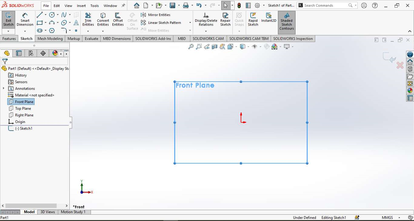
Step 1 – Part Creation:
The process began by opening SOLIDWORKS and creating a new Part document. A sketch was initiated on the Front Plane to begin shaping the base profile of the object.
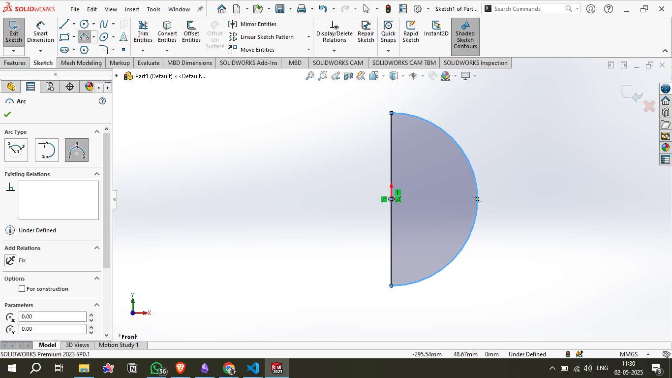
Step 2 – Sketching the Profile:
A semicircular arc was drawn along with a vertical line to form the profile of a sphere. This sketch defined the basic shape that would later be revolved into a 3D body.
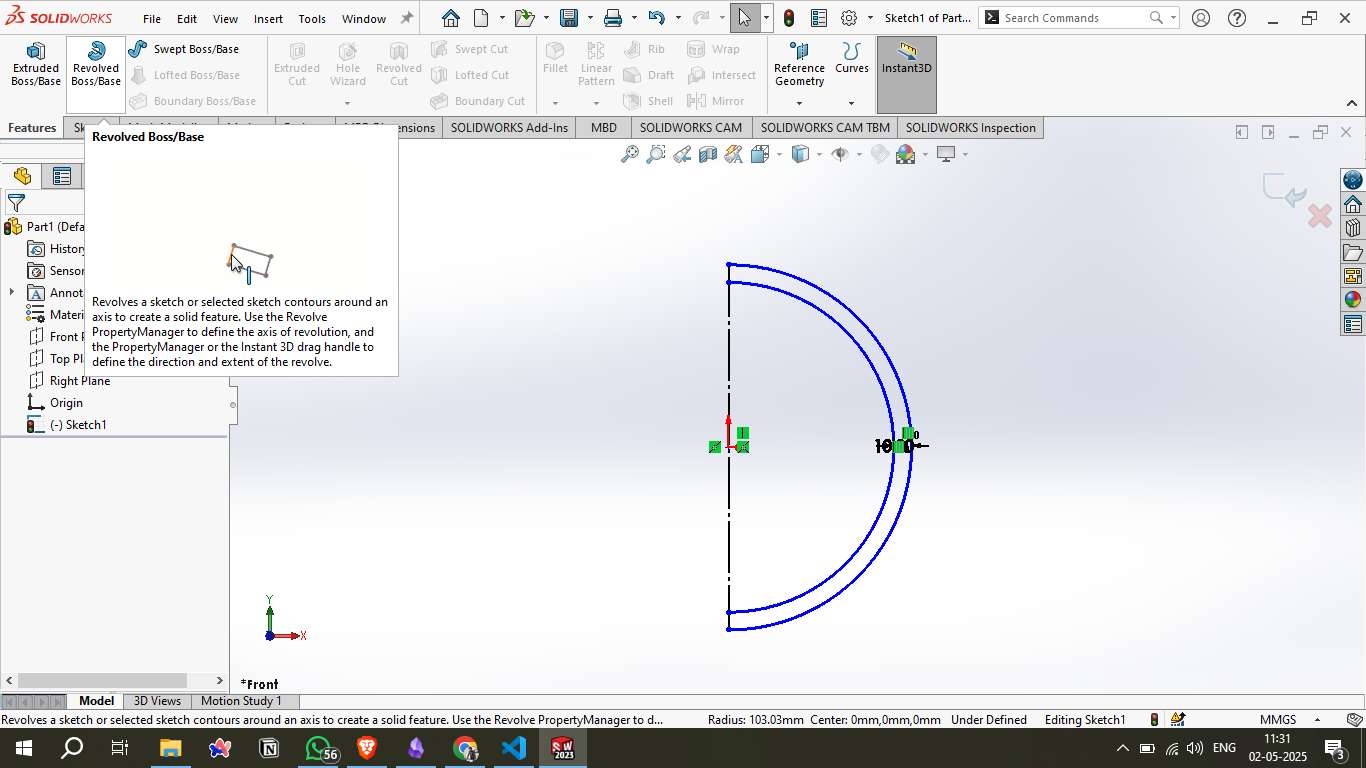
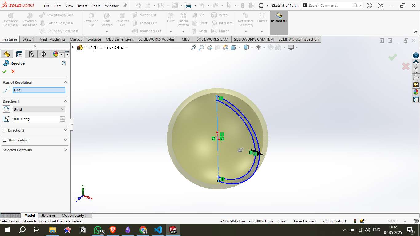
Step 3 – Revolve Feature:
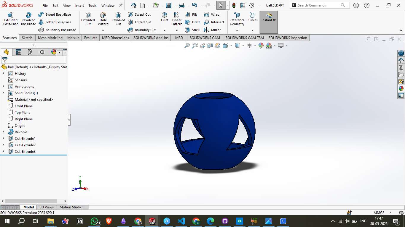
Using the Revolved Boss/Base feature, the semicircle was rotated 360° around the central axis to form a complete sphere. This became the base body for all subsequent operations.
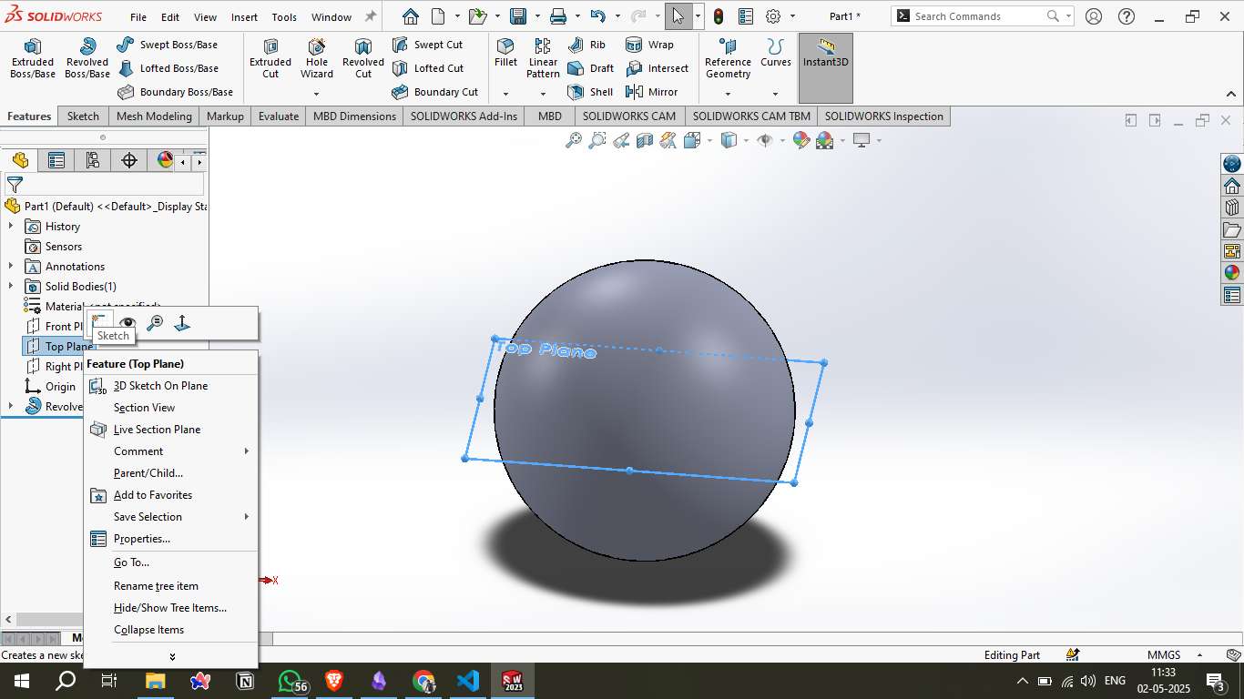
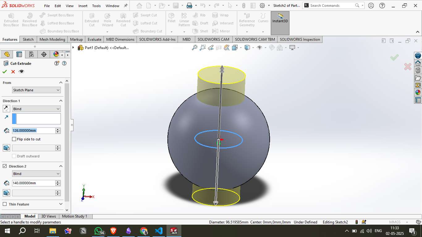
Step 4 – Top Cut Creation:
A circular cut was made from the Top Plane using the Cut-Extrude tool. This created an open top on the sphere, introducing a hollow passage and internal visibility.
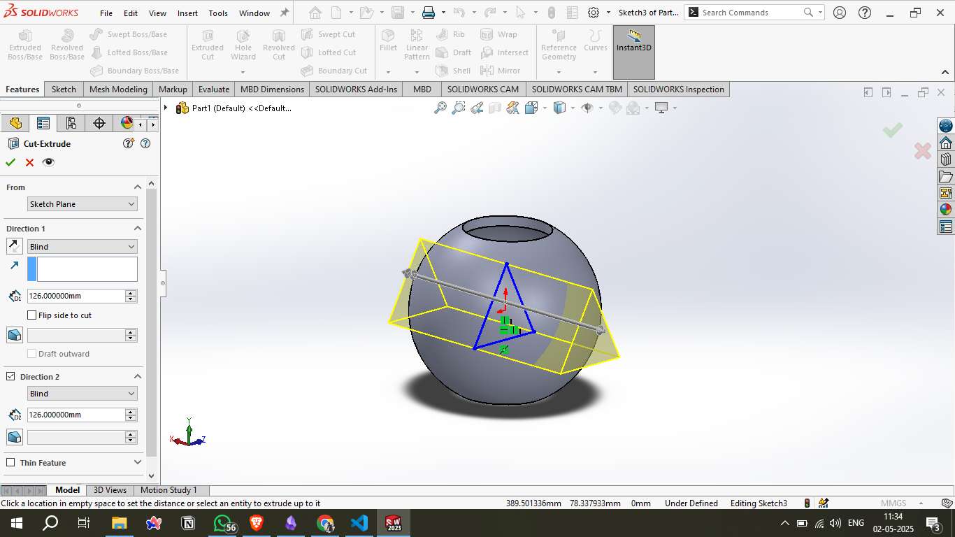
Step 5 – Triangular Cutout:
An angled reference plane was created and used to sketch a triangle. This triangular profile was then extruded through the sphere in both directions, forming a sharp, internal cutout that passes through the body.
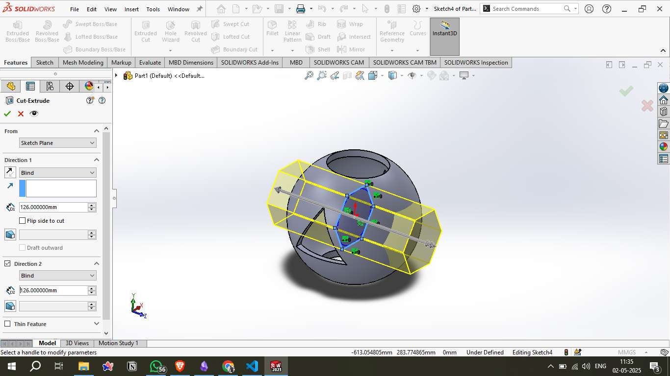
Step 6 – Intersecting Cut:
A second cross-cut was created from a different angle with a circular or hexagonal shape. This cut intersected with the previously formed internal geometry, creating a complex network of openings.
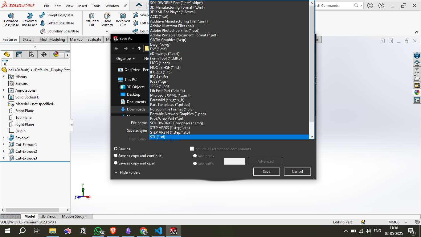
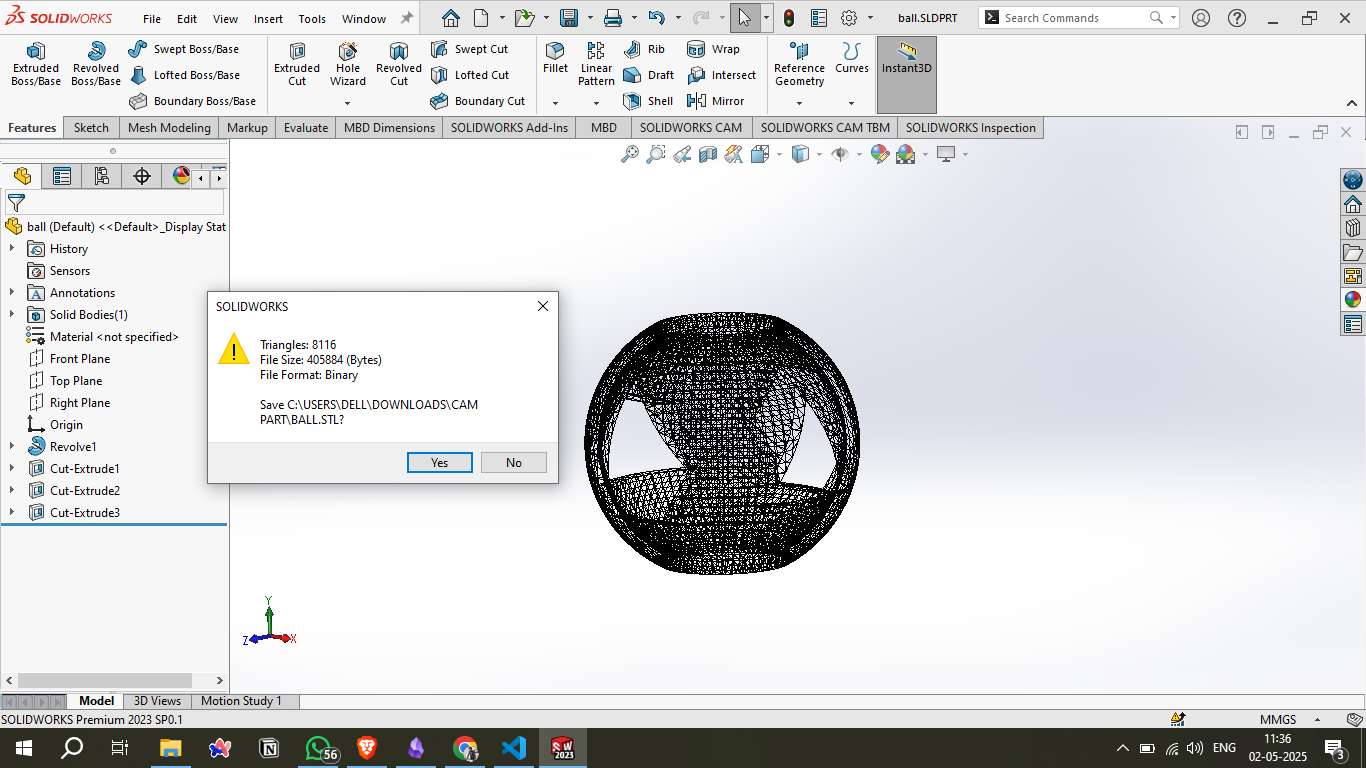
Step 7 - Exporting the 3D Model as STL:
Once the 3D design was finalized in SOLIDWORKS, it was exported in the STL format, suitable for 3D printing. The mesh had 8,116 triangles and a size of 405 KB, ensuring a well-optimized model for slicing.
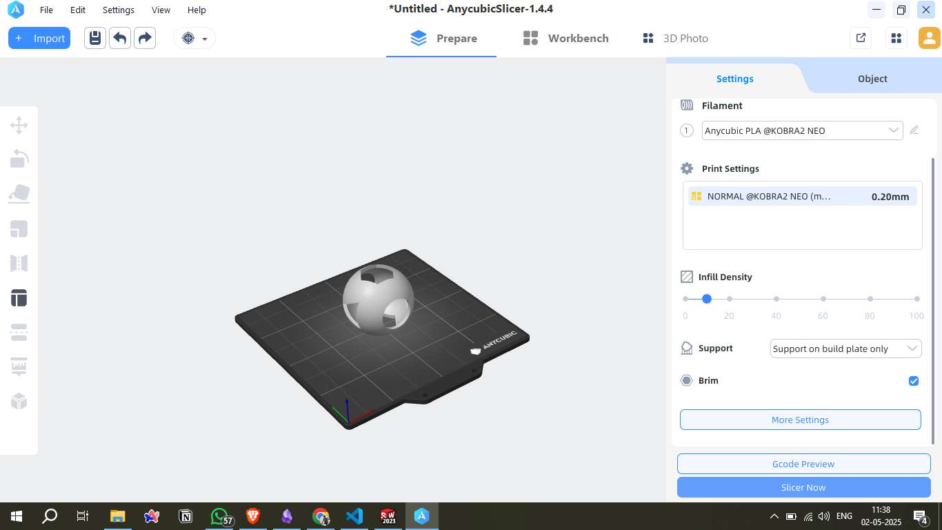
Step 8 - Opening the STL in Anycubic Slicer:
The STL was imported into Anycubic Slicer v1.4.4 for use with the Anycubic Kobra 2 Neo printer. The model was placed on the virtual build plate, and slicing settings such as PLA filament and 0.20 mm layer height were selected.
Visit Anycubic Official Website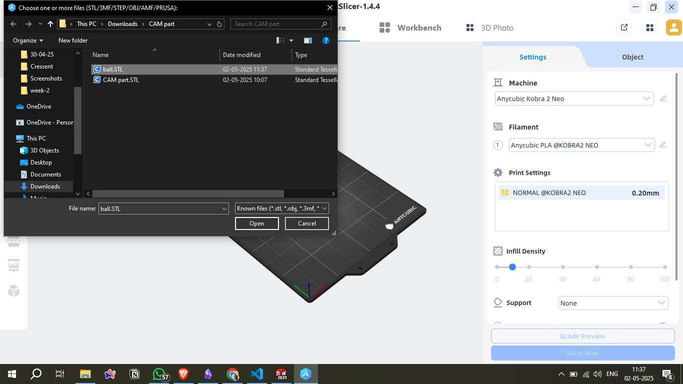
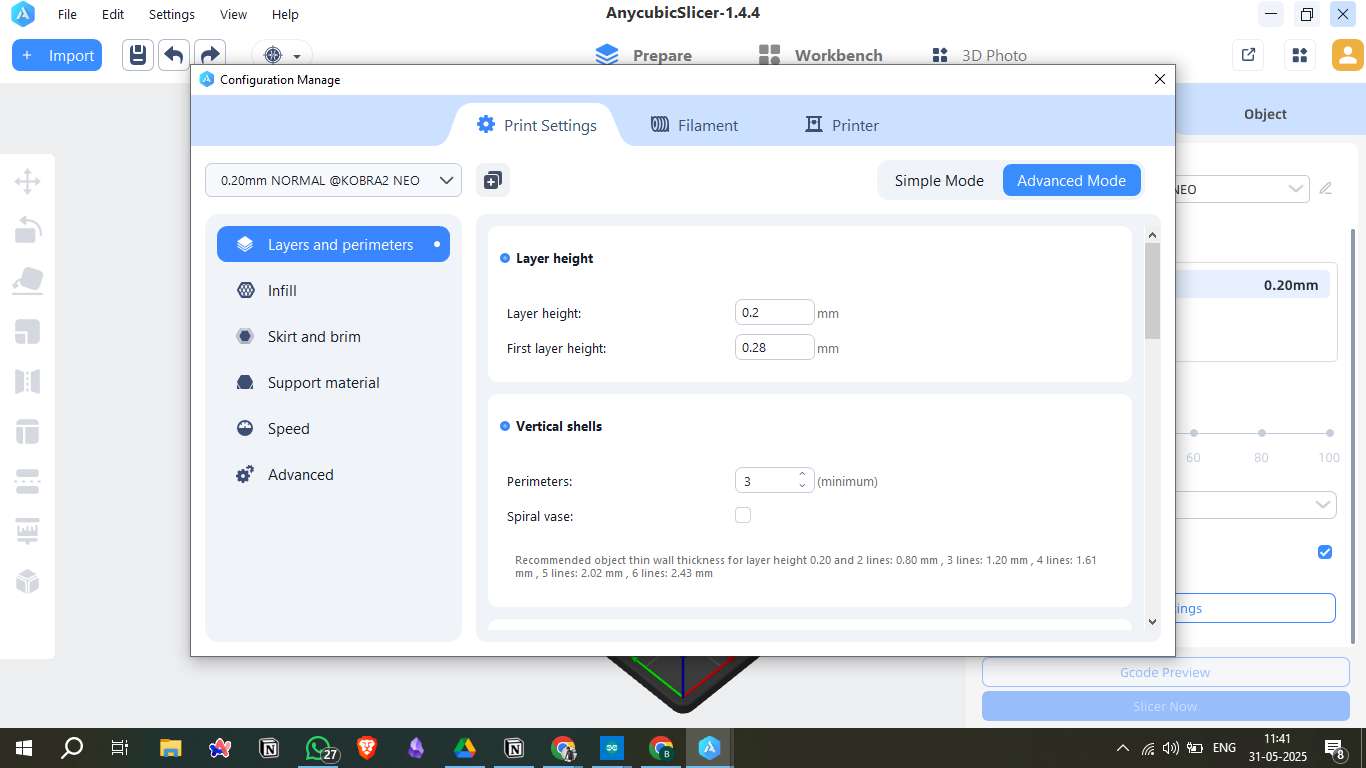
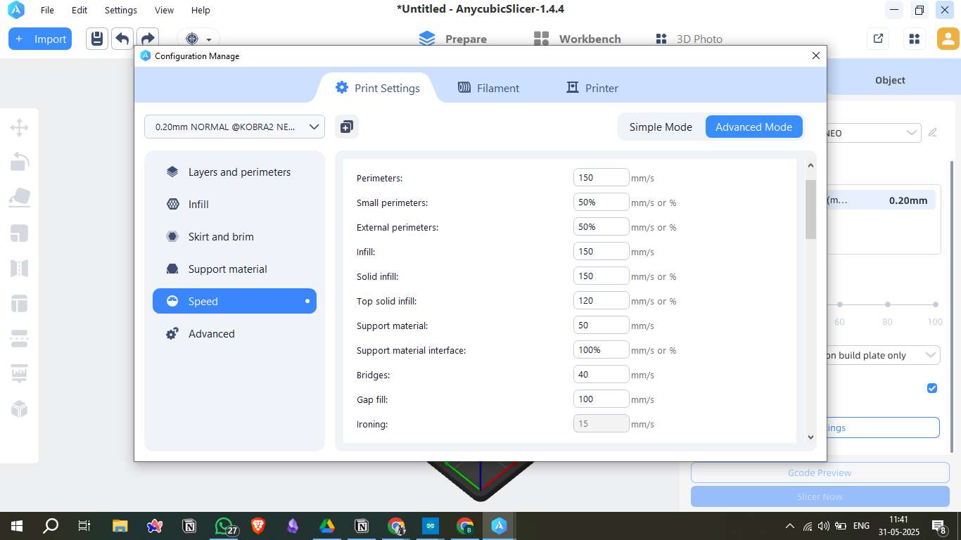
Step 9 - Slicing Settings Configuration in Anycubic Slicer
To prepare my 3D model for printing, I used Anycubic Slicer version 1.4.4 with the printer profile set to KOBRA2 NEO and layer height profile of 0.20mm NORMAL. Below are the customized slicing parameters I used:
1. Layers and Perimeters
- Layer height: 0.2 mm
- First layer height: 0.28 mm (to improve bed adhesion)
- Perimeters: 3 vertical shells for structural strength
- Spiral vase: Disabled
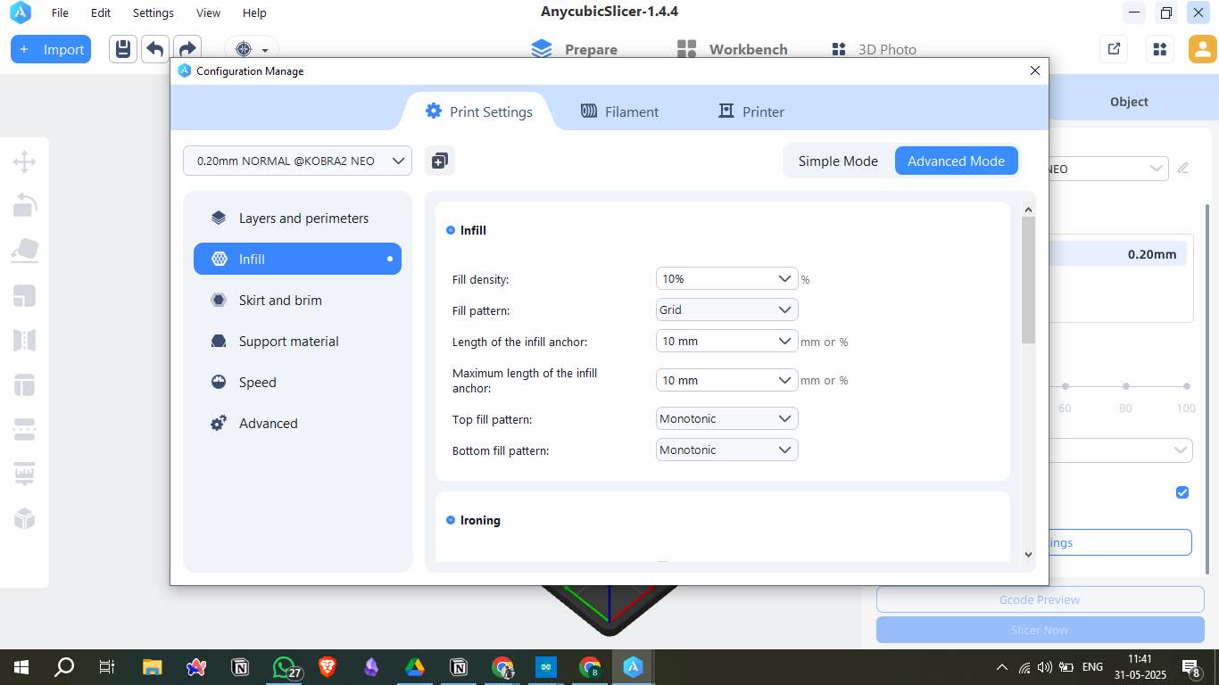
2. Infill Settings
- Fill density: 10% (for faster print and material saving)
- Fill pattern: Grid
- Top/Bottom fill pattern: Monotonic
- Infill anchor length: 10 mm (for consistent anchoring)
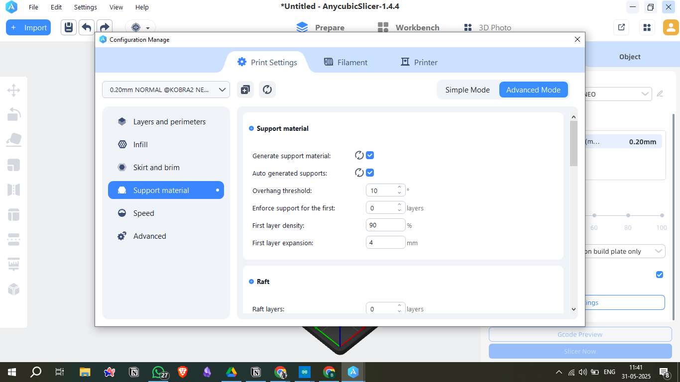
3. Support Material
- Generate support material: Enabled
- Overhang threshold: 10° (for better overhang control)
- First layer density: 90%
- First layer expansion: 4 mm (to enhance support contact)
4. Speed Settings
- Perimeters & infill: 150 mm/s
- Top solid infill: 120 mm/s
- Support material: 50 mm/s
- Bridges: 40 mm/s
- Ironing: 15 mm/s (for surface finishing)
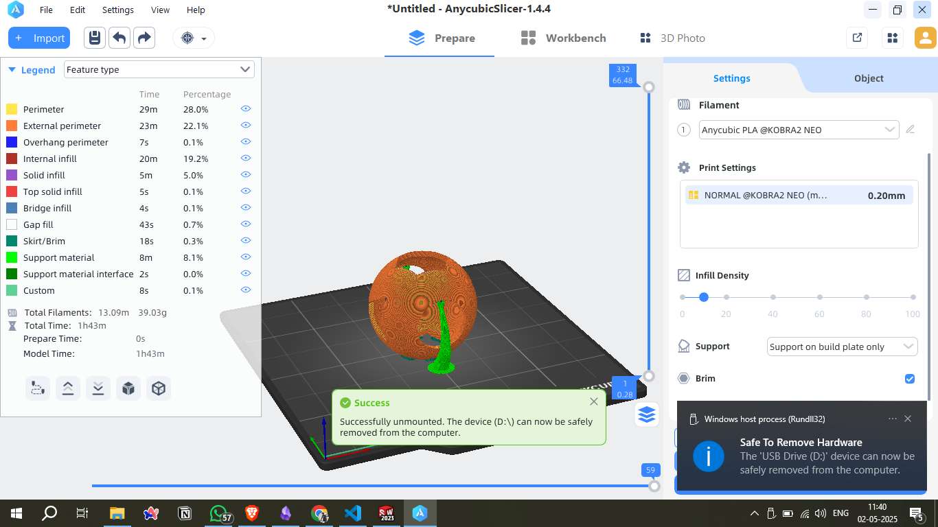
Step 9 - Slicing the Model:
Settings such as infill density, brim support, and build plate adhesion were applied. The slicing process estimated a print time of 1 hour 43 minutes and required approximately 13.09 meters (39.03 grams) of filament.
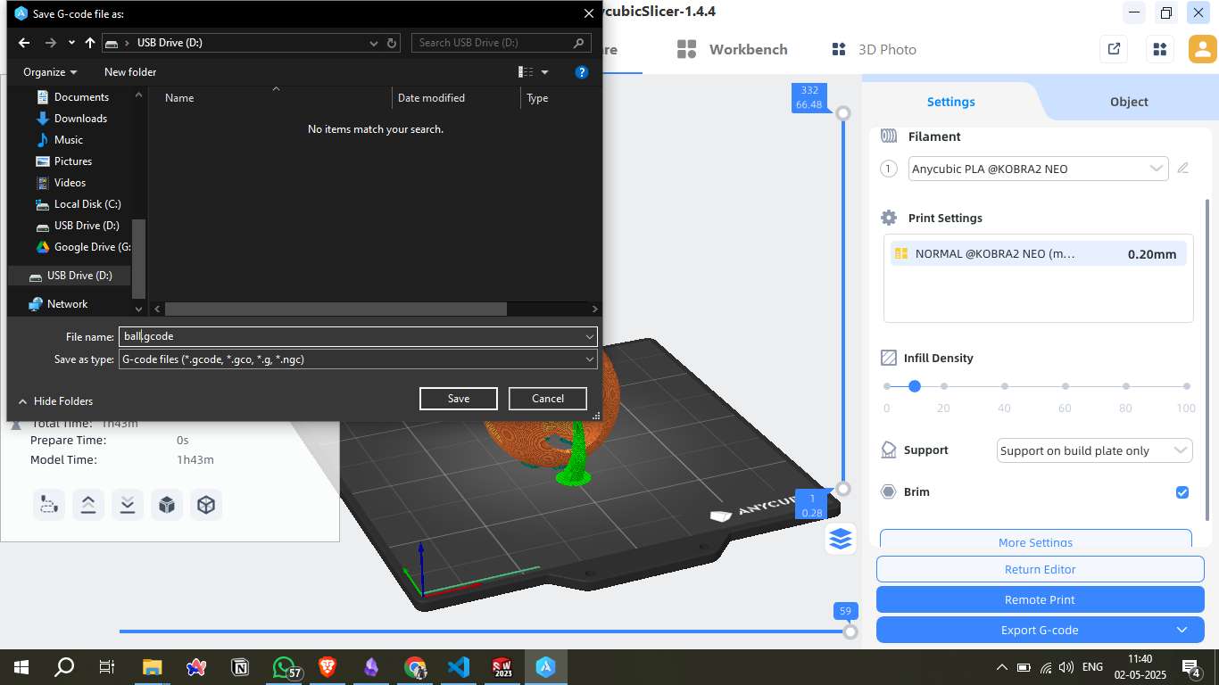
Step 10 - G-code Generation:
The sliced file was exported as ball.gcode and saved to a USB drive. This G-code file contains all the instructions needed by the printer to produce the model.
3. 3D Printing Process
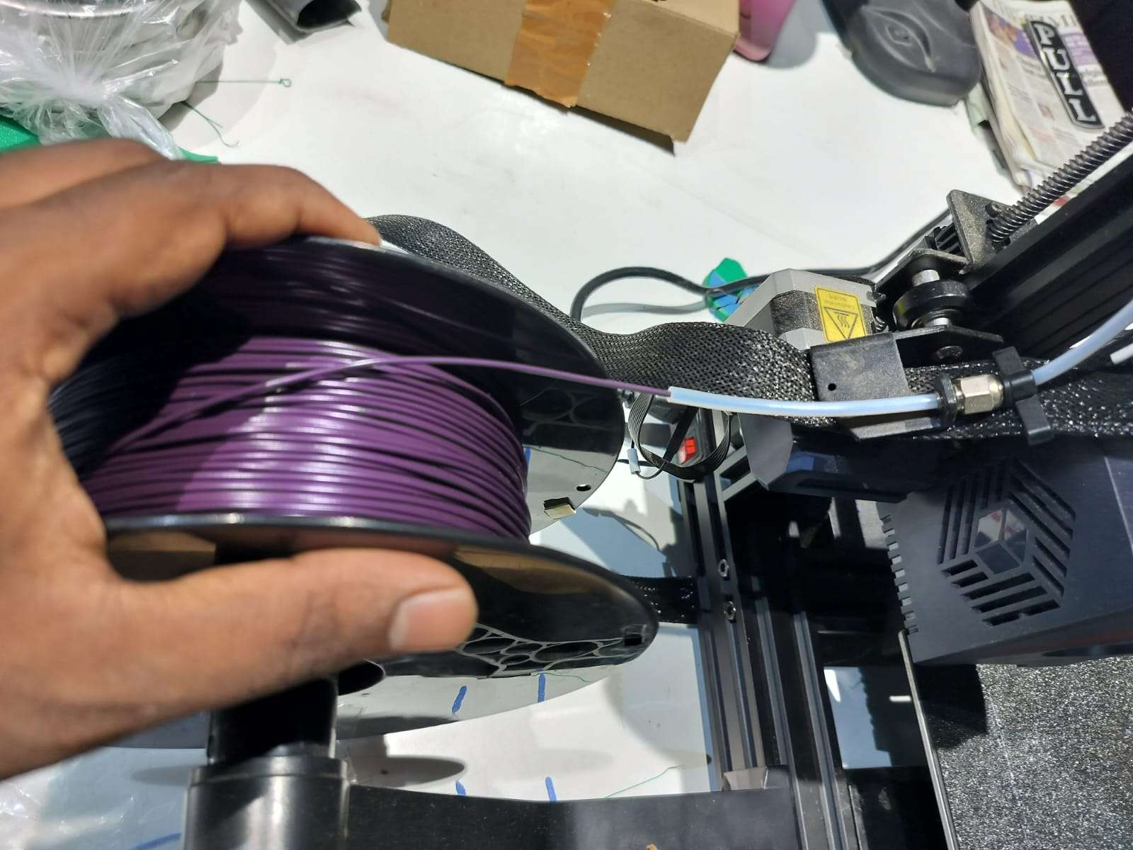
Loading the Filament
I used a 1.75 mm PLA filament of purple color. The filament was loaded into the extruder by manually guiding it through the Bowden tube.
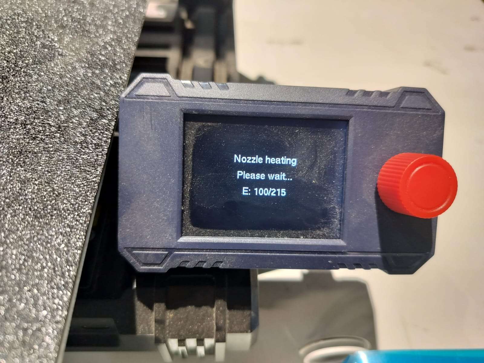
Heating the Nozzle
Before printing, I set the nozzle to heat up to 215°C, which is suitable for PLA material.
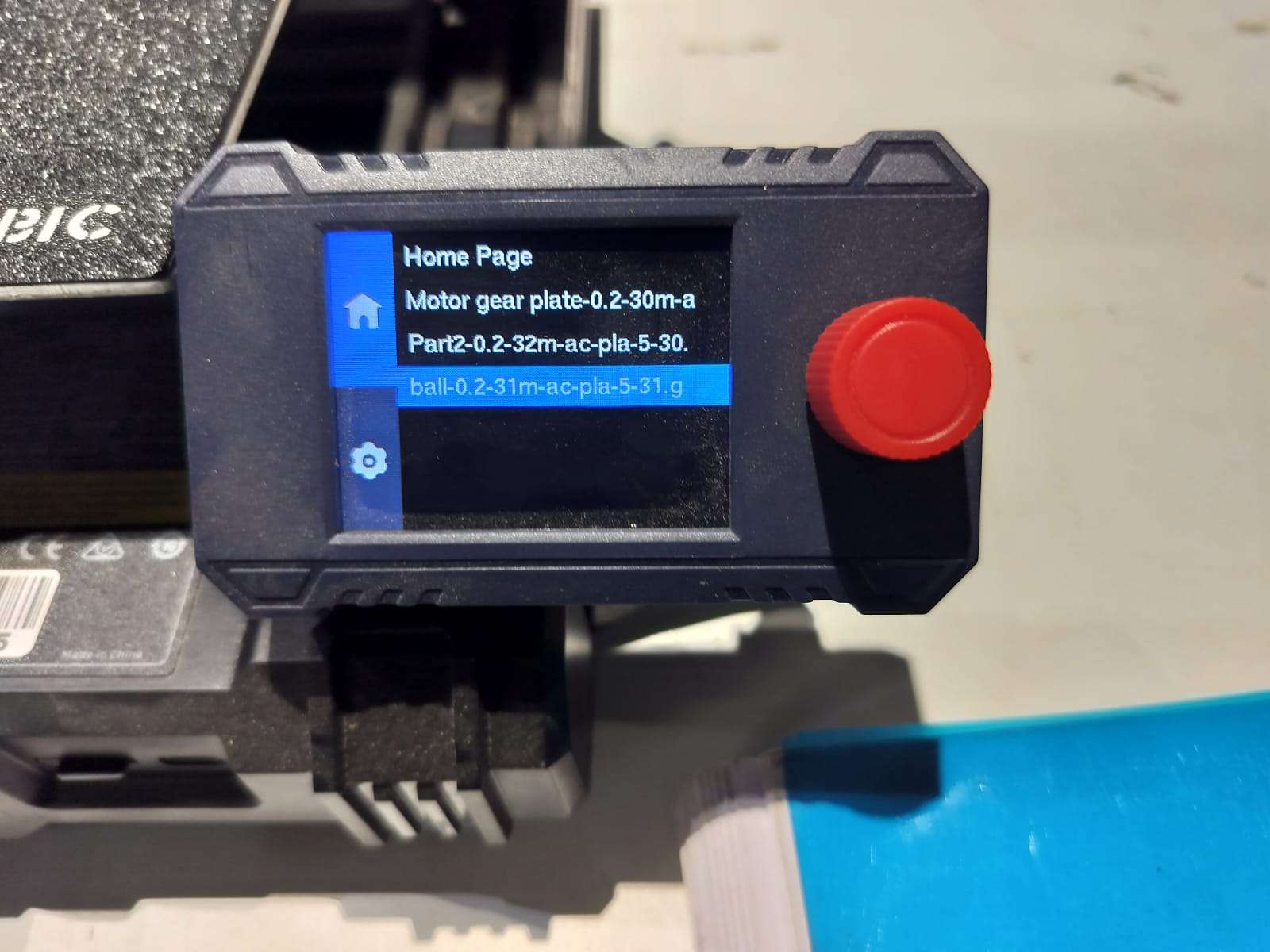
Selecting the Print File
Using the 3D printer interface, I selected the sliced G-code file named ball-0.2-31m-ac-pla-5-31.g for printing.
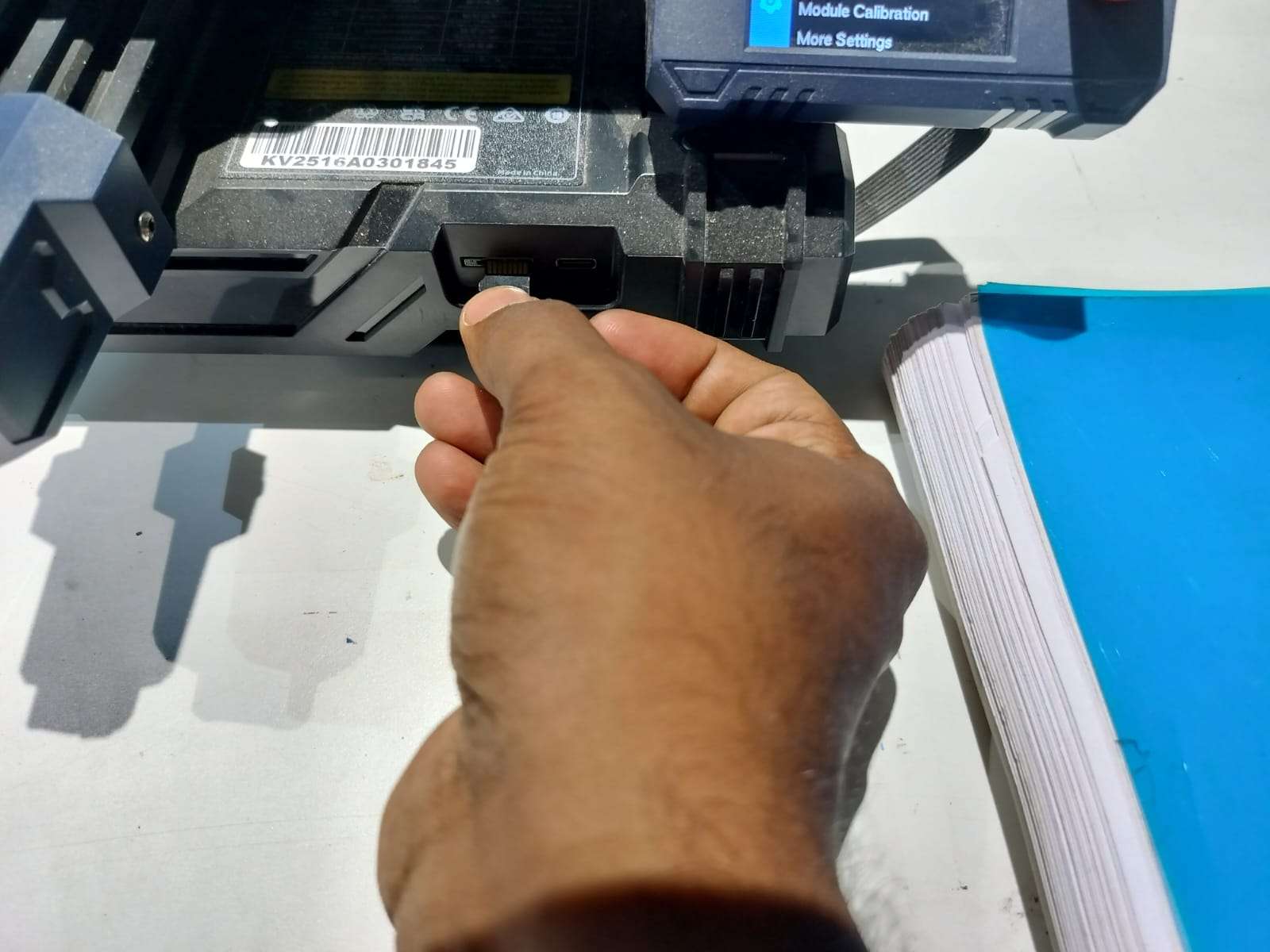
Starting the Print
The sliced file was inserted through a USB stick, and the print was initiated.
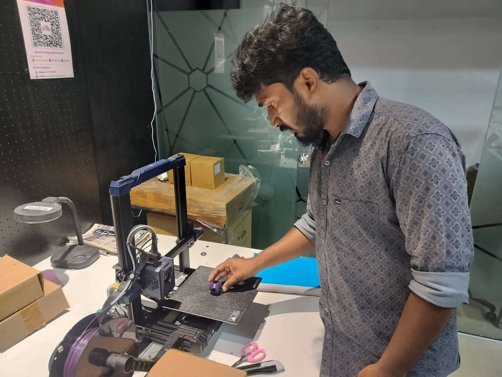
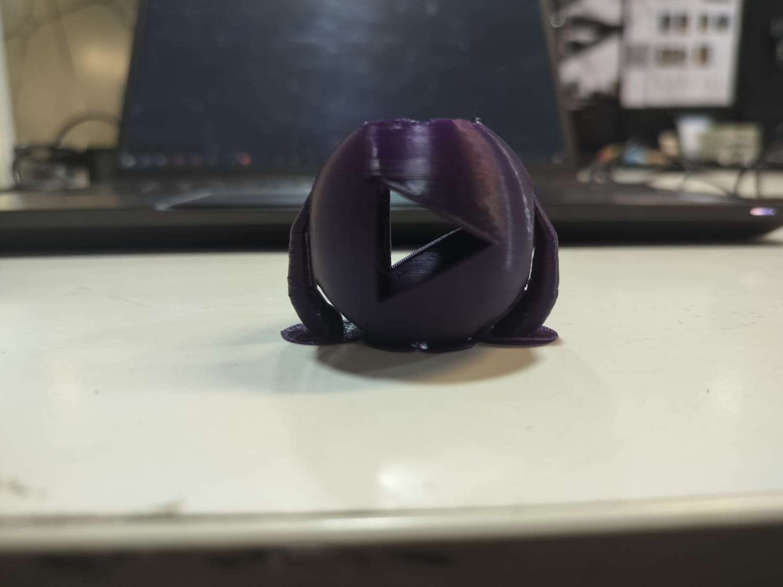
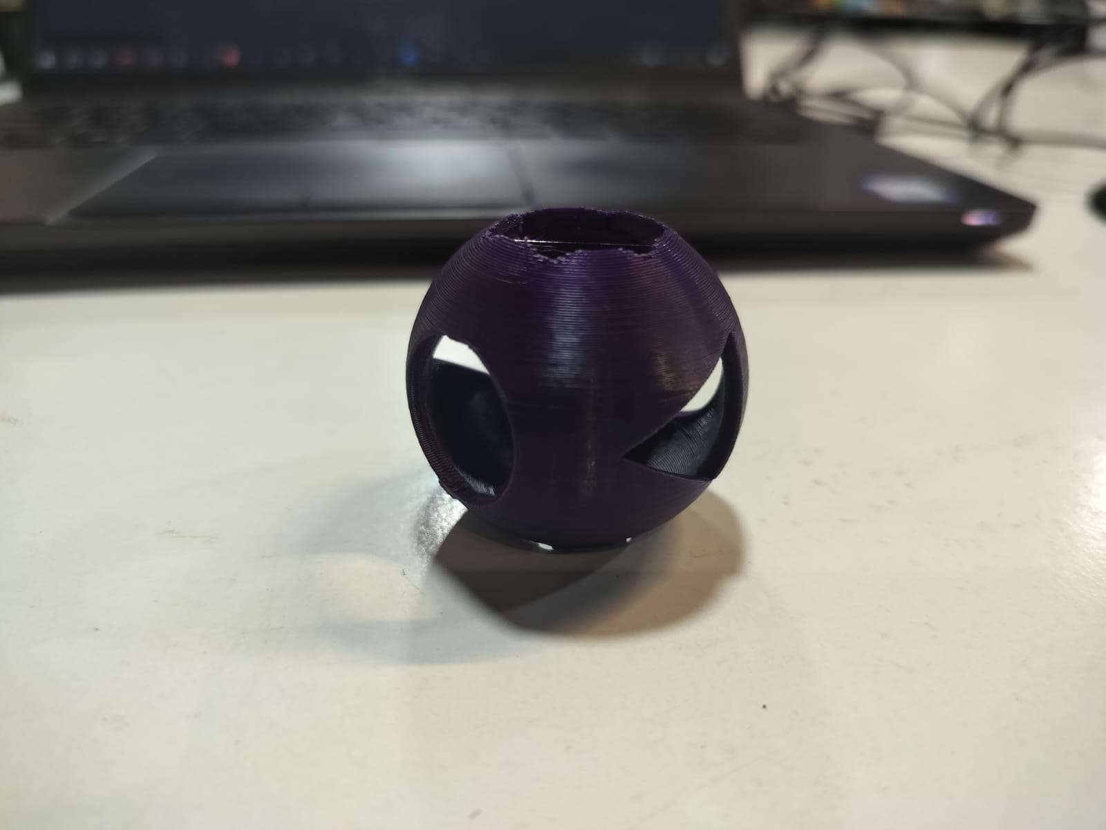
Final Printed Output
The final printed object is a geometrically complex hollow sphere with angled internal cutouts. The print quality was clean, and the overhangs were handled well with the support structures.
Machine & Settings Used
- Printer: Anycubic Kobra Go
- Filament: PLA (1.75 mm, Purple)
- Nozzle Temperature: 215°C
- Bed Temperature: 60°C
- Layer Height: 0.2 mm
- Infill Density: 20%
- Support: Enabled
- Print Time: Approx. 1 hour 30 minutes
Hero shot
Downloadable Files
3D Scanning Process
3D Scanning Process
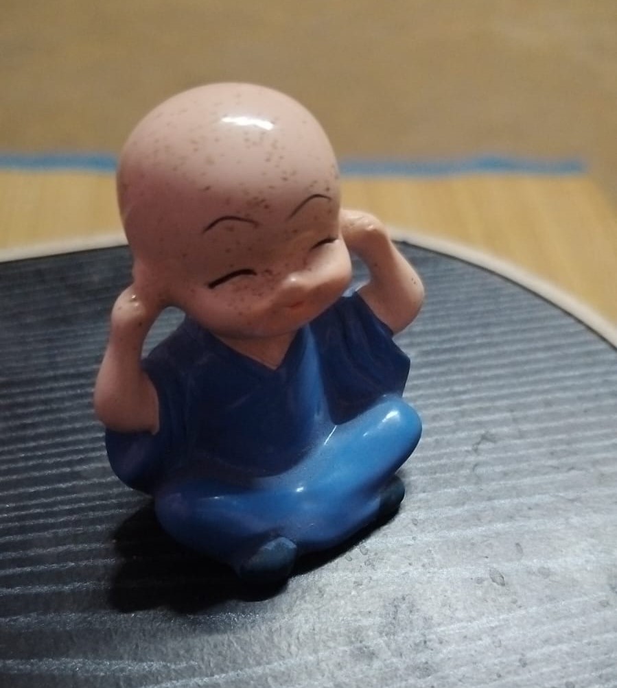
1. Selecting the Object
The object chosen for scanning was a small toy. This was selected due to its distinct shape and well-defined features, making it suitable for 3D reconstruction.
Visit Kiri Engine Official WebsiteThe first image shows the real toy used for scanning.
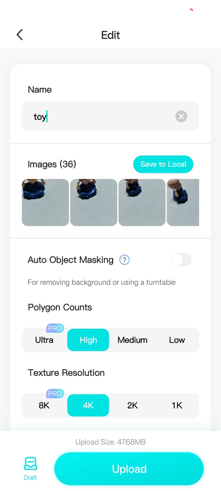
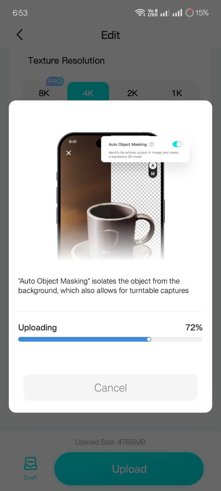
2. Capturing Multiple Angles
To ensure an accurate 3D scan, multiple images of the toy were taken from different angles using the Kiri Engine.
The next image displays the collected photos, covering all perspectives required for proper model generation.
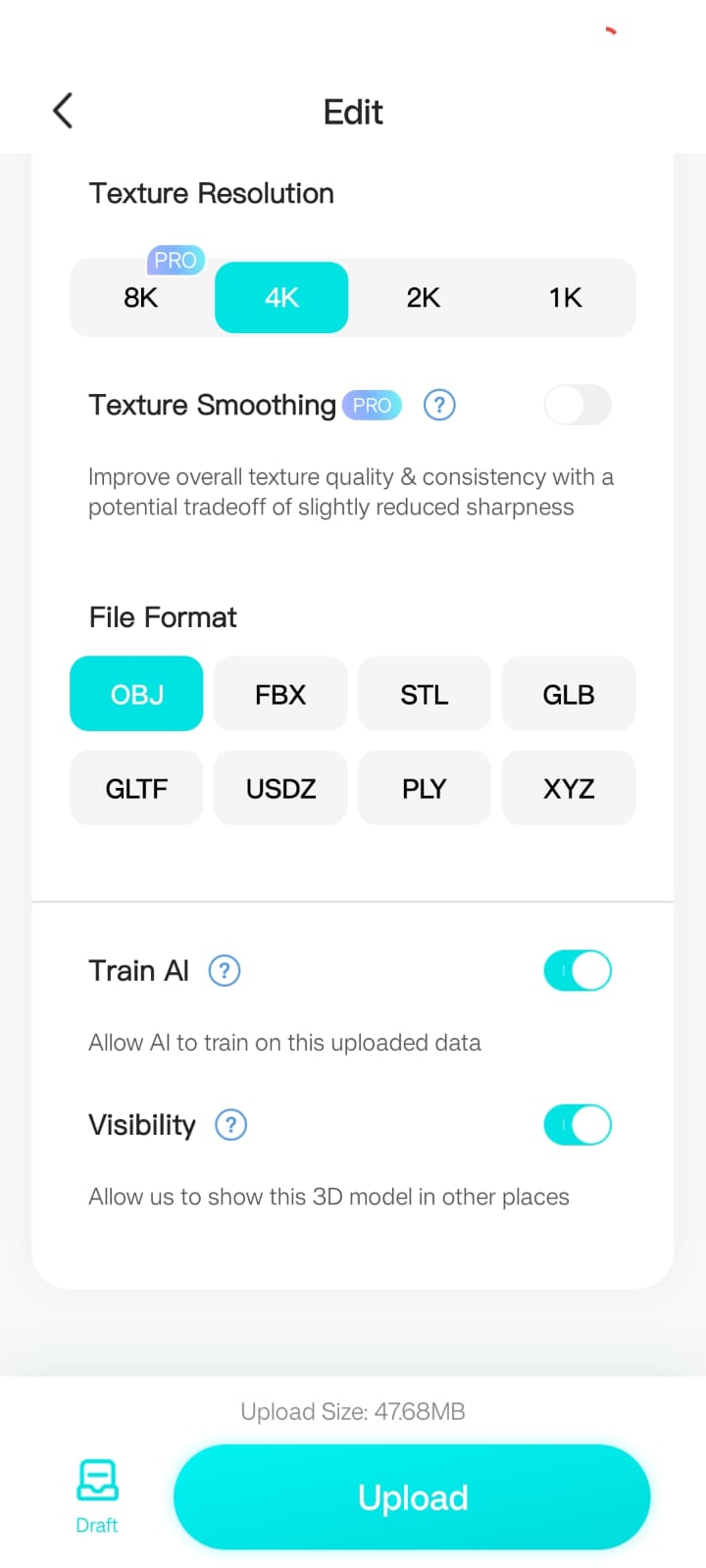
The settings were adjusted to export the model in OBJ format, which is compatible with 3D printing and further modifications.
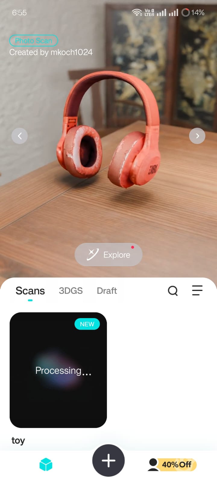
3. Rendering and Viewing the 3D Model
The app processed the images and generated a 3D model, converting it into a mesh representation.
Once the rendering was complete, the OBJ file was displayed within the Kiri Engine.
The generated model was inspected for accuracy, ensuring that the shape and details were preserved from the original object.
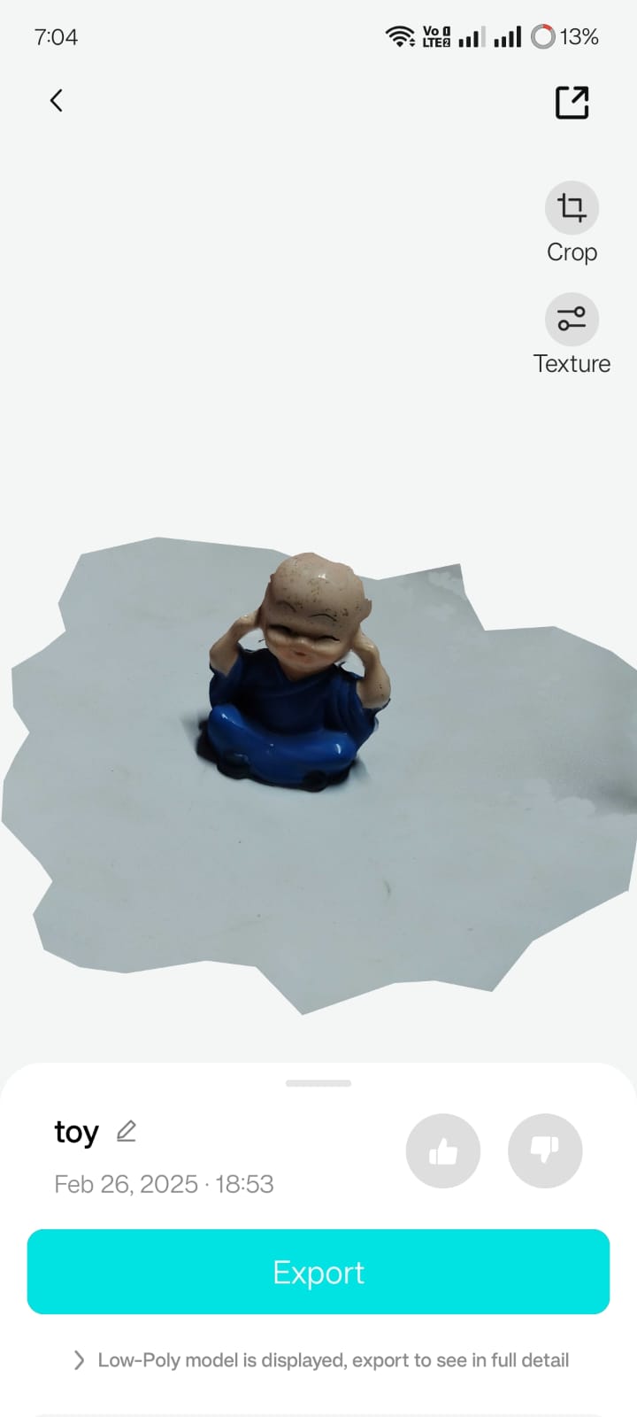
4. Final Out
The next image presents the final 3D file of the scanned object.
Once the rendering was complete, the OBJ file was displayed within the Kiri Engine.
The generated model was inspected for accuracy, ensuring that the shape and details were preserved from the original object.
Downloadable Files
Table of Contents
- Software Used
- Step 1 – Part Creation
- Step 2 – Sketching the Profile
- Step 3 – Revolve Feature
- Step 4 – Top Cut Creation
- Step 5 – Triangular Cutout
- Step 6 – Intersecting Cut
- Step 7 – Exporting the 3D Model as STL
- Step 8 – Opening the STL in Anycubic Slicer
- Step 9 – Slicing the Model
- Step 10 – G-code Generation
- Step 11 – Hero shot
- 3D scanning
- 1. Selecting the Object
- 2. Capturing Multiple Angles
- 3. Rendering and Viewing the 3D Model
- 4. Final Out