Final Project
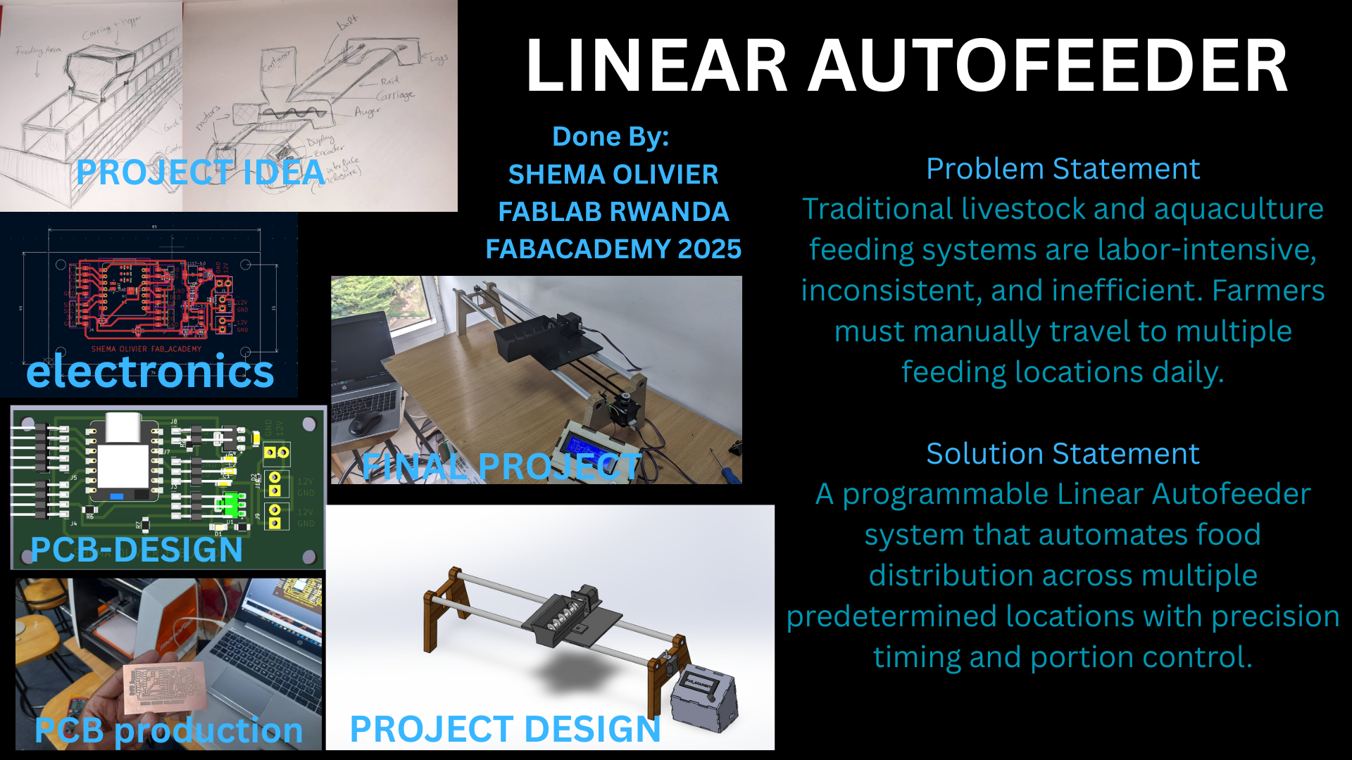
Final Project Documentation: Linear Autofeeder
1. Introduction & Project Background
Origin of the Idea
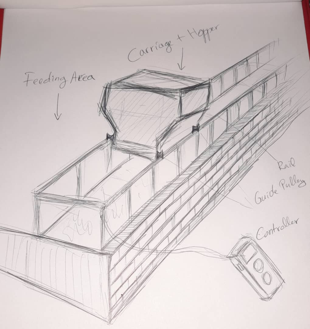
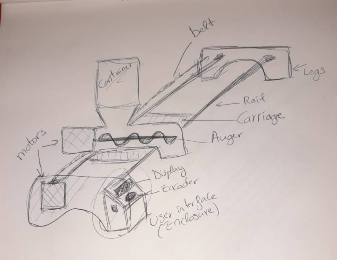
During the very first week of Fab Academy, under the theme “Plan and sketch a potential final project,” I explored ideas that could blend personal relevance with real-world agricultural impact. Inspired by this YouTube Short , which showed a large-scale automatic cattle feeder, I imagined creating something similar: a smart system that would automate feeding in livestock farms.
However, I quickly realized that the scale of such a cattle-feeding system would be difficult to prototype within the Fab Academy timeframe and resource limits. That’s when I decided to develop a smaller, more manageable version, one that retained the core principles of automated feeding and mechanical delivery but was more feasible in scope.
I then found further inspiration in this Instagram Reel, which showcases a rail-based feeding system simple, smart, and modular. This design helped guide my final direction: a Linear Autofeeder that travels along a path and dispenses food precisely where it's needed.
Personal Motivation
This wasn’t just a technical challenge. It was personal.
I come from a family that raises a small group of cattle for dairy production , and I’ve experienced firsthand how time-consuming and inconsistent manual feeding can be. By automating this process, even in a small prototype, I saw the potential to improve efficiency, reduce labor, and ensure better care for animals, starting with cattle but easily adaptable to other uses.
National Context & Impact
Rwanda is actively working to increase its dairy and fish production as part of broader national goals in food security and smart agriculture. This Linear Autofeeder project directly aligns with that vision, combining automation, low-cost prototyping, and digital fabrication to deliver a real-world solution.
While the prototype focuses on fish farming and small enclosures, it can be scaled up and modified for:
- Cattle or poultry feeding systems
- Aquaculture (fish cage farming)
- Other rural or off-grid smart agriculture setups
2. What Does It Do?
The Linear Autofeeder is an automated rail-based system that moves to pre-set positions and dispenses food using an auger mechanism. It is designed to:
- Automate feeding cycles for animals or fish.
- Deliver consistent food quantities.
- Reduce manual labor and errors.
- Operate reliably with user-configurable settings.
Main features include:
- Microcontroller-based control using a XIAO ESP32C3.
- Dual stepper motors for rail movement and auger operation.
- LCD and rotary encoder interface for user configuration.
- Emergency stop and endstop limit switches for safety.
3. Applications
Real-world Use Cases
- Cattle Farming: Automate silage or dry feed delivery along feeding troughs.
- Aquaculture: Feed fish at precise intervals along cages or tanks.
- Poultry Farming: Deliver grain or pellets along coops.
- Greenhouses: Modified to dispense nutrients or water along rows.
- Education & Prototyping: Serves as a demo for motion control, embedded systems, and system integration.
4. Implications
Why It Matters
- Reduces labor and increases consistency in feeding routines.
- Supports precision agriculture and smart farming.
- Encourages local production of automation tools in agriculture.
- Provides a scalable platform: the same logic can be adapted to other linear distribution systems.
5. Who’s done what beforehand?
Initial Research and Inspirations
Before designing the Linear Autofeeder, I conducted research on similar projects and mechanisms, both for linear motion and automated feeding. This helped shape the concept, understand common approaches, and avoid reinventing the wheel.
Linear Motion Inspiration (Camera Sliders):
- Camera slider projects were a great starting point to understand smooth linear movement using stepper motors and rails.
- These videos provided insight into how to implement motion control, limit switches, and structural design.
Feeding System Inspiration:
- A key turning point in the project came when I found a video of a cattle feeding machine that distributes food along a row.
Automatic Cattle Feeder (YouTube Shorts)
This inspired the concept of adapting that idea to aquaculture and small-scale farming.
Existing Products: King of Feeders
- I also looked at existing commercial solutions, such as King of Feeders, which offers mechanized feeders.
Combined Inspiration: Linear + Feeding:
- Finally, I found a reel that blended both ideas (linear motion and feeding system), confirming that the combination is feasible and practical.
Conclusion:
This body of research validated that while similar concepts exist, this project offers a unique take by emphasizing local fabrication, educational value, and modular integration, with a strong focus on DIY and accessible tools.
6. Personal Contribution and Mastery
- Designed all parts in CAD (SolidWorks) from scratch.
- Printed and assembled all 3D components, CNC parts and LASER CUTTER parts.
- Designed and produce the PCB from scratch using KiCad and Roland.
- Wired and tested all electronics using breadboards and prototypes.
- Wrote firmware to handle motion, display, inputs, and emergency handling.
- Validated system integration through multiple test cycles.
- Documented the full development process, including challenges and solutions.
7. Materials & Components Used
| Item | Quantity | Source | Cost |
|---|---|---|---|
| XIAO ESP32C3 | 1 | https://www.nyerekatech.com | Fr20,000 |
| NEMA 17 Stepper Motors | 2 | https://www.nyerekatech.com | Fr29,600 |
| TB6600 Motor Drivers | 2 | https://www.nyerekatech.com | Fr30,000 |
| 20x4 LCD Display | 1 | https://www.nyerekatech.com | Fr10.500 |
| Rotary Encoder | 1 | https://www.nyerekatech.com | Fr3,000 |
| AMS1117 Regulato | 2 | https://www.nyerekatech.com | Fr1,000 |
| Wires, Screws, PCB, Capacitors, Resistors, switches | - | Fab Inventory | Fr20,000 |
| PLA Filament and MDF | - | Fab Lab | - |
| Aluminum Rail | 2m | Local Vendor | Fr10,000 |
| Total Approximate Cost: | Fr104,100 |
8. What I Designed for this Project.
I designed and built
9. Parts and Systems that were made.
| Component | Software/machines | Comments |
|---|---|---|
| Carriage, Hopper, Auger | SolidWorks for designs, ultimaker cura to slice, creality 3D printer for the FDM printing. | Settings: 0.2mm layer height, 20% infill, PLA material. |
| Enclosure Panels | SolidWorks for designs and 2D, 5mm MDF sheet, laser cutter | Settings: Optimized power/speed for clean cuts.Precise fitting with minimal post-processing for the assembly |
| Legs supports | SolidWorks for designs and 2D, 18mm MDF sheet, CNC machine | sanded for smooth parts then assembled with the tube rail. |
| PCB | KiCad for schematic and PCB design, modsproject.org for the G-codes, Roland MonoFab for the milling. | Surface-mount and through-hole component soldering. Continuity testing and functional verification. |
| Firmware (Software) | Arduino IDE for the coding | use of ChatGPT and Claude.ai for debugging the codes |
10. The Questions that were answered
Motion Control:
- Can stepper motors provide sufficient precision? Yes, 200 steps/second provides smooth, accurate positioning
- Is belt drive reliable for outdoor use? Yes, with proper tensioning and weather protection
- How accurate is the positioning system? Achieves ±5mm repeatability over 0.6-meter travel
Feeding Mechanism:
- Does auger system work? Successfully tested
- Is feeding auger speed consistent? Achieves a consistency with proper calibration
User Interface:
- Is LCD menu system intuitive? User testing confirms easy operation after brief testing
- Can settings be saved reliably? EEPROM storage maintains settings through power cycles
Scalability:
- Can design be adapted for larger farms? with some modifications to make it bigger and longer rails, it can be possible.
11. What worked? What didn't?
Successful Elements:
Motor Control System:
- AccelStepper library provided smooth, reliable motion control
- Position tracking and homing system worked flawlessly
User Interface:
- LCD menu system proved intuitive and responsive
- Rotary encoder provided precise input control
- EEPROM storage reliably maintained settings
Mechanical Design:
- The 3D-printed components—carriage, auger, and hopper—demonstrated adequate strength and precision, making them well-suited for their roles in the system.
- The rail system provided smooth and accurate linear motion, which was essential for precise positioning of the feeder along the path.
- The CNC-cut parts provided a strong and stable structure for supporting the rail and the other components mounted on it.
- The enclosure was designed to fit all the components neatly, including the LCD display, rotary encoder, PCB, and the two motor drivers. Everything fit as expected, and the integration was successful.
Challenges and Solutions:
Initial Encoder Sensitivity Issues:
- Problem: Original encoder required excessive rotation for response
- Solution: Enhanced interrupt handling and position tracking algorithm
- Result: Smooth, responsive user input with minimal rotation
Motor Noise Without Movement:
- Problem: Motors made noise but didn't rotate initially
- Solution: Optimized speed settings and improved step timing
- Result: Reliable motor operation with proper acceleration curves
Belt Tension Variability:
- Problem: Belt drive system required frequent tension adjustments
- Solution: Added tension adjustment mechanism (Screws) and better belt guides
- Result: Consistent performance with periodic maintenance
Ongoing Optimization Areas:
Power Efficiency:
- Current system could benefit from sleep modes during inactive periods
- Solar power integration being explored for off-grid operation
Communication Features:
- WiFi connectivity for remote monitoring under development
- Data logging capabilities for feeding optimization
Feeding Precision:
- Load cell integration for weight-based feeding being tested
- Automatic calibration features under development
12. Designs of the project
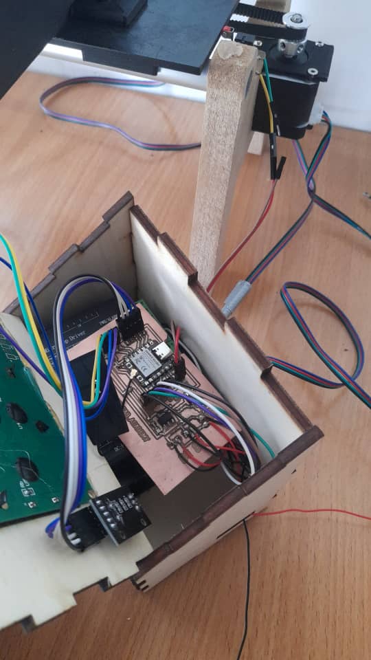
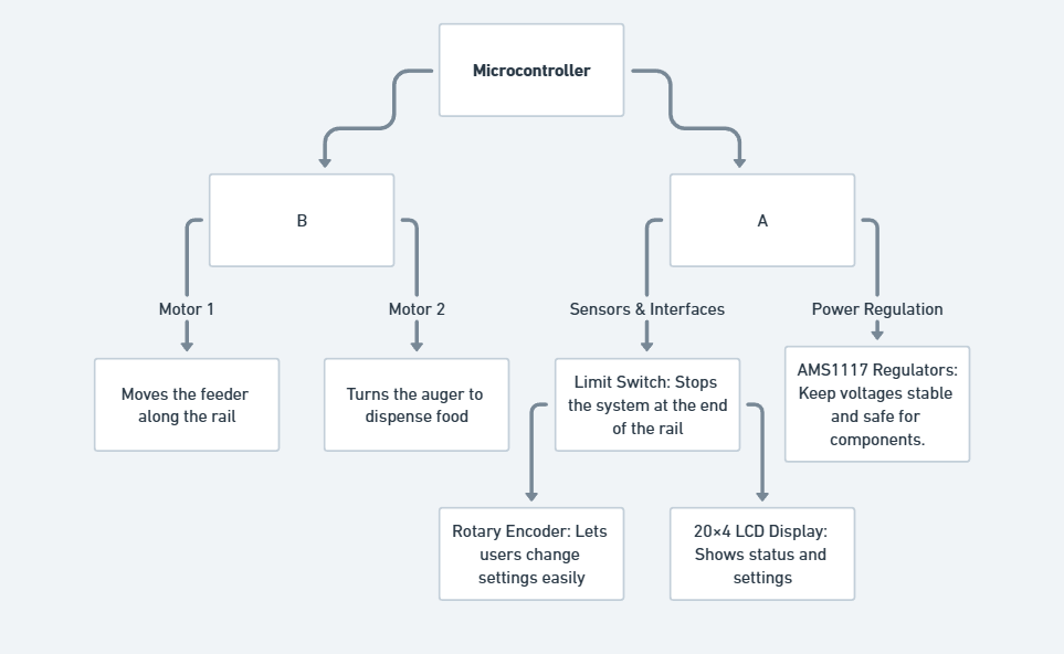
A. Electronics
To bring the Linear Autofeeder to life, I designed an electronic system that controls the motors, reads user input, and displays information. The main components include a microcontroller, stepper motors, drivers, sensors, a display, and voltage regulators.
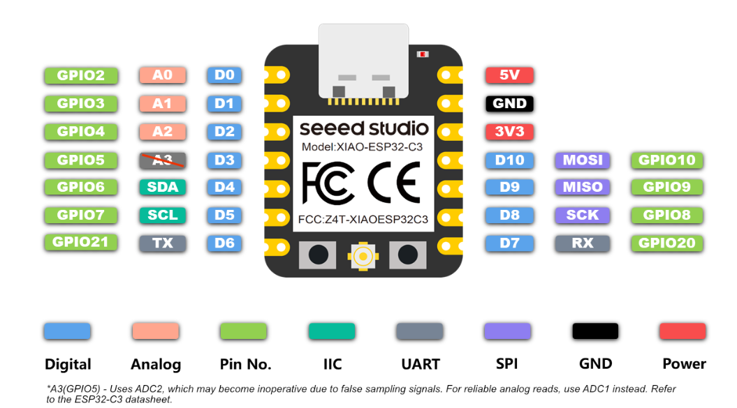
I started by reviewing the pinout of the XIAO ESP32C3, which I chose as the main microcontroller for the project. This helped me plan how each component would connect and ensured I used the available pins efficiently.
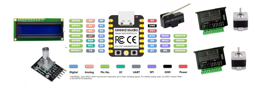
Next, I selected the key components for the project, including two NEMA 17 stepper motors with their TB6600 drivers, an LCD display, a rotary encoder, and a limit switch. These components were chosen to handle movement, user input, and safety functions within the system.
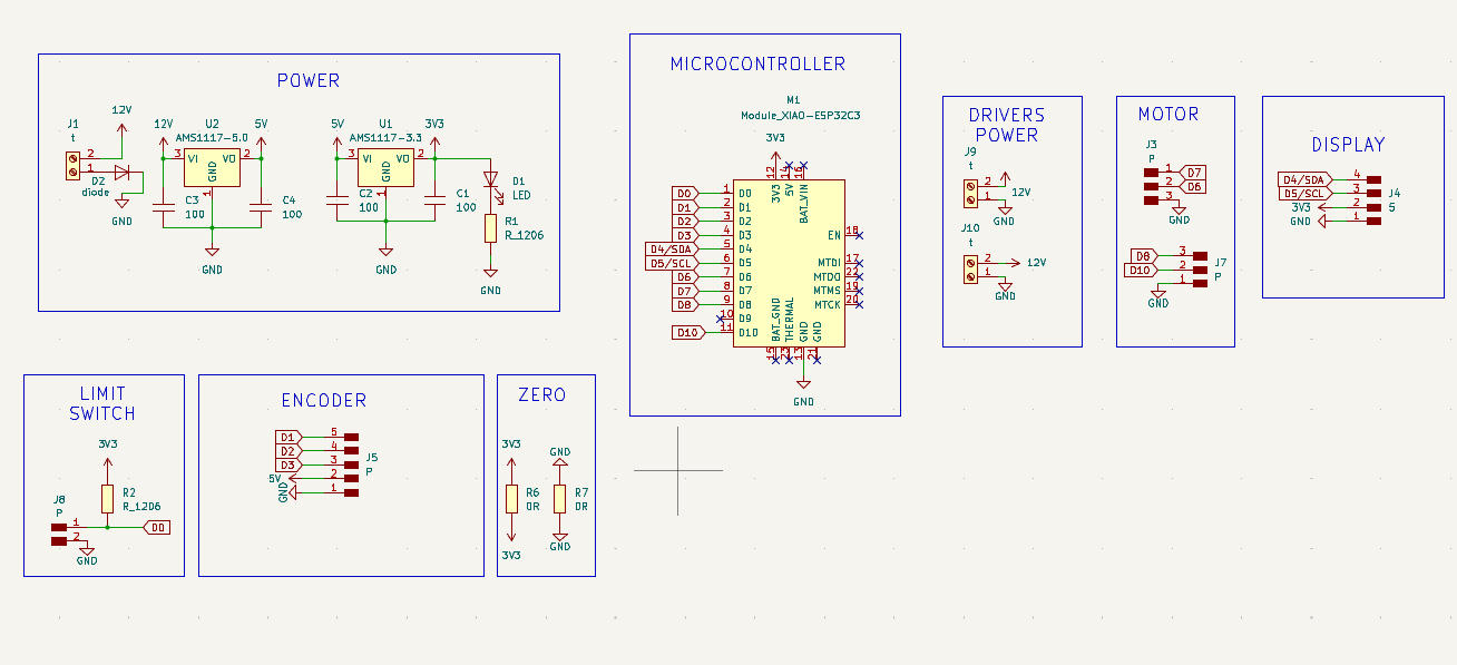
After selecting the components, I created a schematic in KiCad to show how everything would be connected. I also added power sources with different voltage levels: 12V for the stepper drivers, 5V for the encoder, and 3.3V for the XIAO ESP32C3. To manage this, I used AMS1117 voltage regulators to step down the voltages as needed for each component.
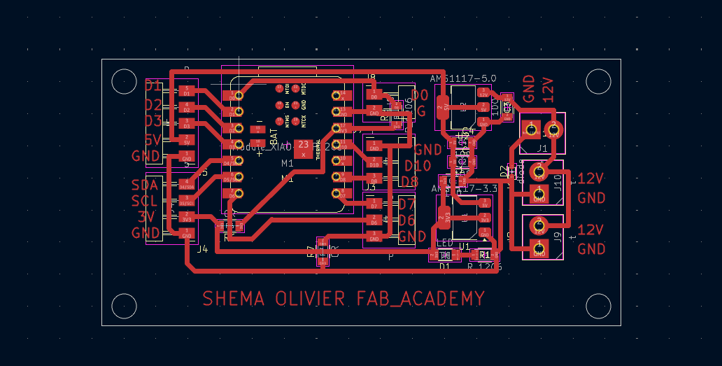
In KiCad PCB Editor, I routed the connections between components based on the schematic and arranged them to fit neatly on the board. After finalizing the layout, I generated the design files to create a custom PCB for my project.
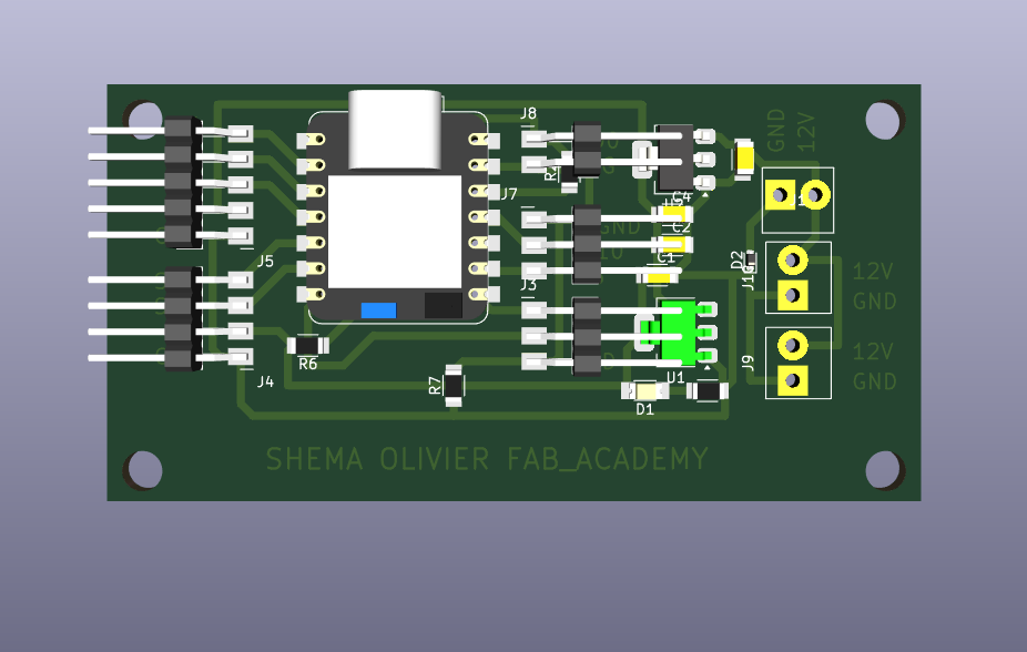
Here is the PCB layout view, showing the final arrangement and routing of all components before fabrication.
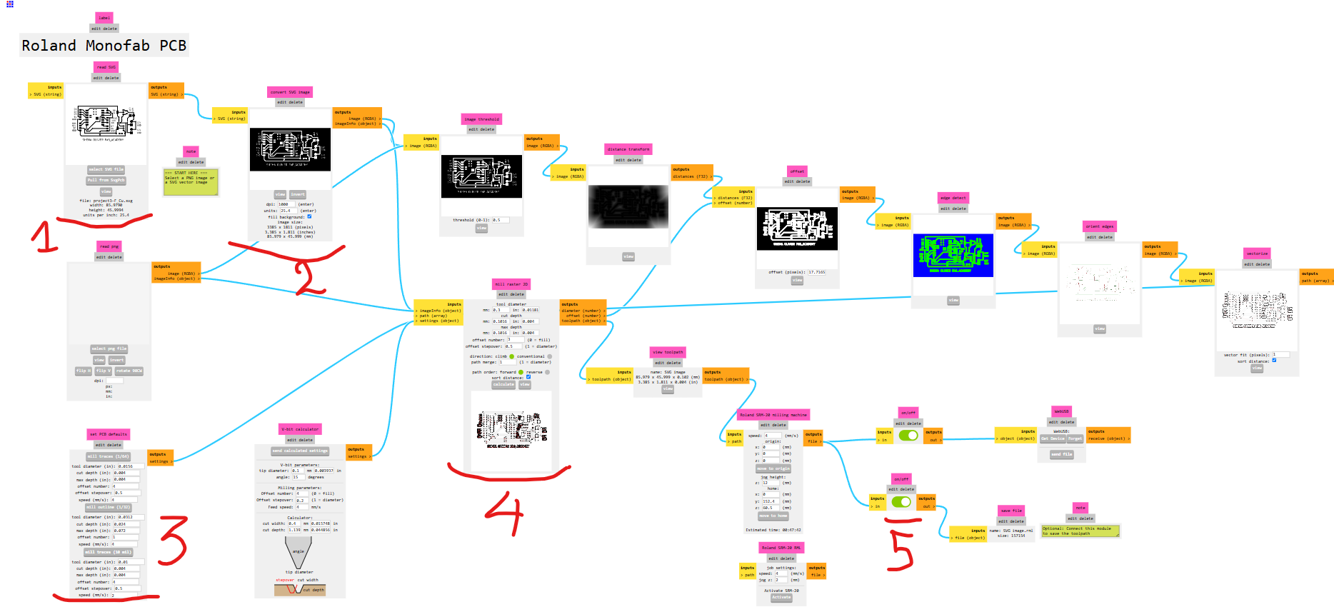
After completing the PCB design, I generated SVG files for the board. Since I was using a Roland MonoFab PCB milling machine, I needed to convert the design into compatible G-code. To do this, I used ModsProject, which allowed me to generate the toolpaths needed for milling.
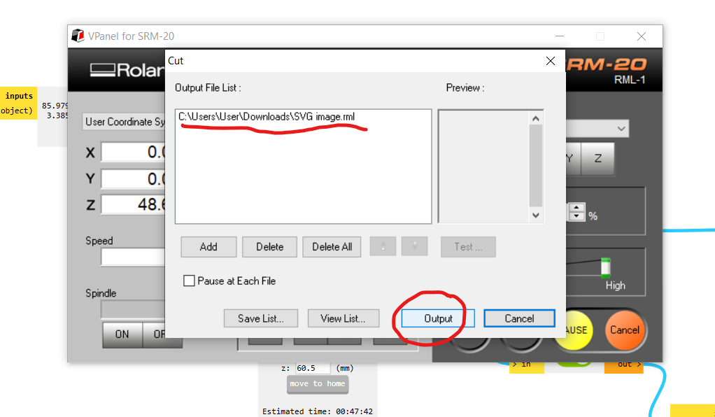
I then opened the generated G-code in VPanel, the control software for the Roland MonoFab. After setting the origin and securing the copper board, I started the PCB milling process.
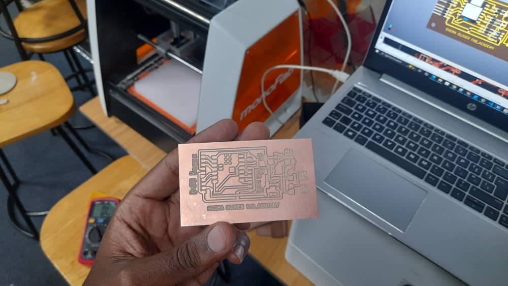
The video shows the Roland MonoFab milling the PCB, accurately carving the traces from the copper board.
B. Mechanical Components
I designed the mechanical parts to support the feeder’s movement and food dispensing. This includes an aluminum rail for smooth travel, a 3D-printed carriage to hold the mechanism, a hopper to store the food, a 3D-printed auger to release it, and an enclosure to protect everything. I aimed to use as many digital fabrication machines as possible from what we learned during Fab Academy. For the rail supports (legs), I used the CNC machine; for the auger and carriage, I used the 3D printer; and for the enclosure, I used the laser cutter.
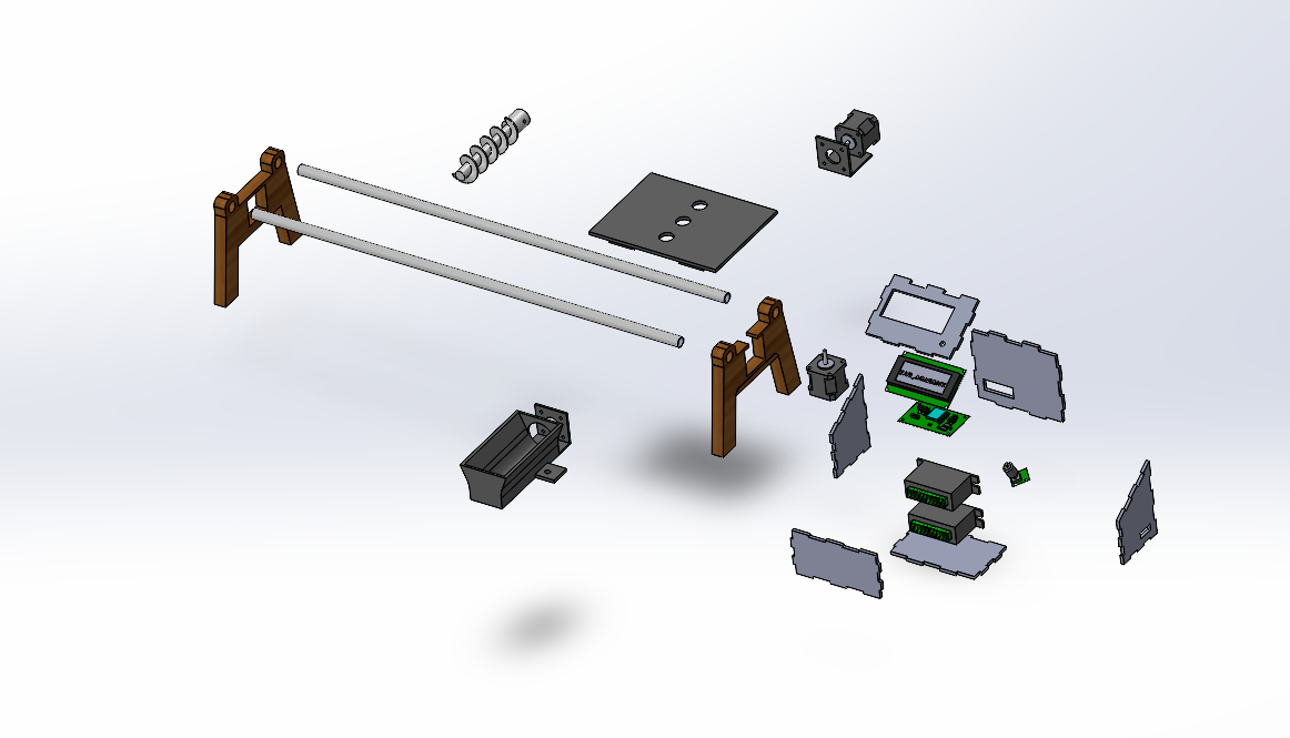
To visualize the complete system, I designed the entire project in SolidWorks, including all mechanical and structural parts. This helped me check how everything would fit together. This is an exploded view of the assembly, showing all the components clearly.
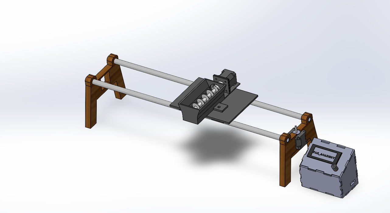
The assembly
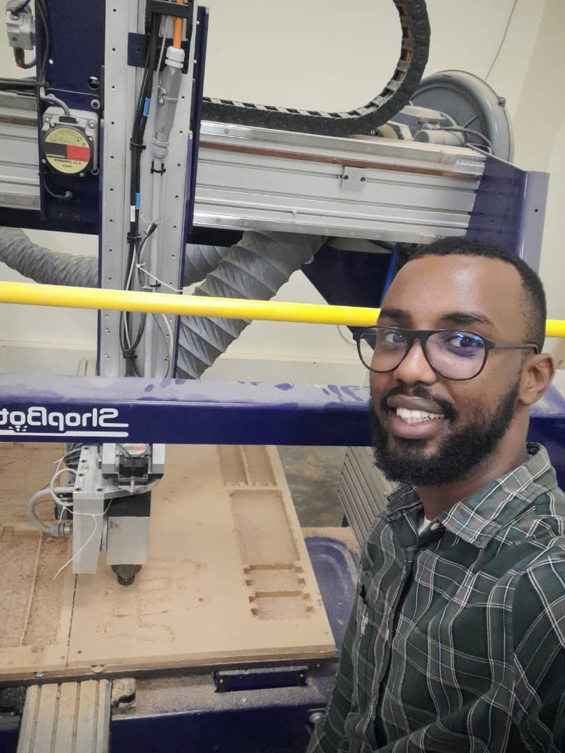
For the legs, I used the CNC machine to cut the parts from MDF, as shown in the picture above. This provided strong and stable support for the rail system.
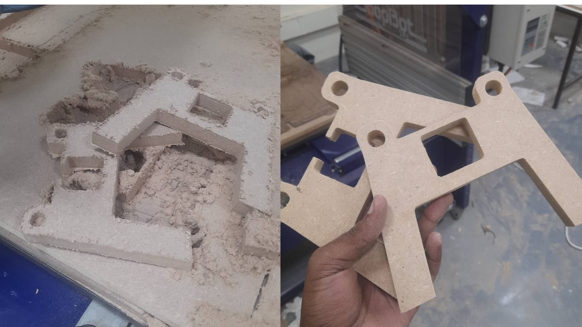
After cutting, I sanded the CNC parts to make the surfaces smooth and ready for assembly.
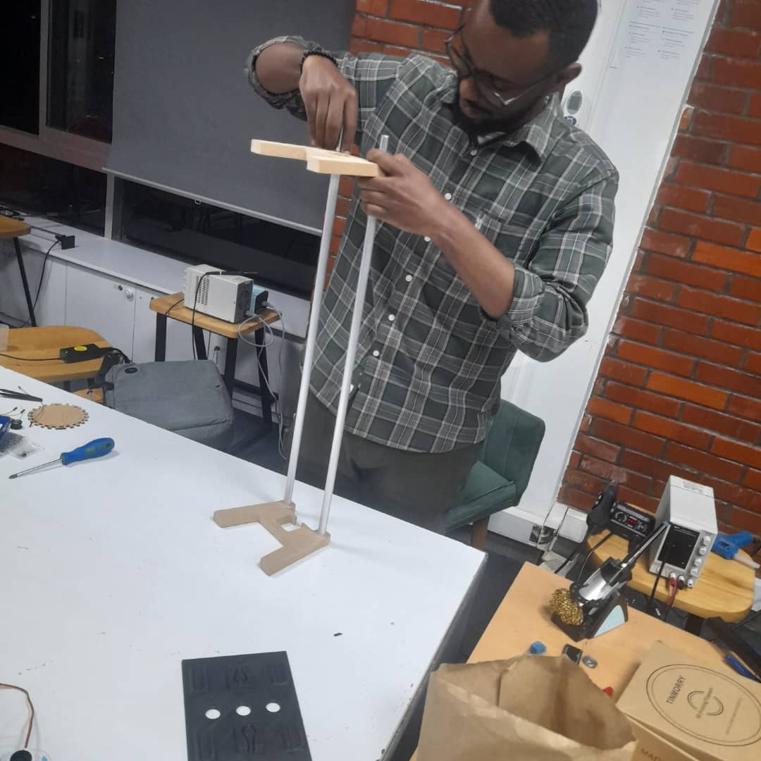
I then assembled the CNC-cut legs with the aluminum rail tube, forming the main support structure for the feeder.
For the auger, hopper, and carriage, I saved the designs as STL files, sliced them, and used the 3D printer to fabricate each part. The video above shows the hopper being printed during the process.
For the enclosure, I saved the designed parts as DXF files and used the laser cutter to cut them from 5 mm MDF. The process is shown in the video above.
C. Firmware (Software)
The final part of the project was writing the firmware, which was the most challenging for me due to my limited coding experience. To make the logic easier to understand, I created a flowchart of the system using Mermaid. For debugging and troubleshooting, I relied on AI tools for guidance and support throughout the process.
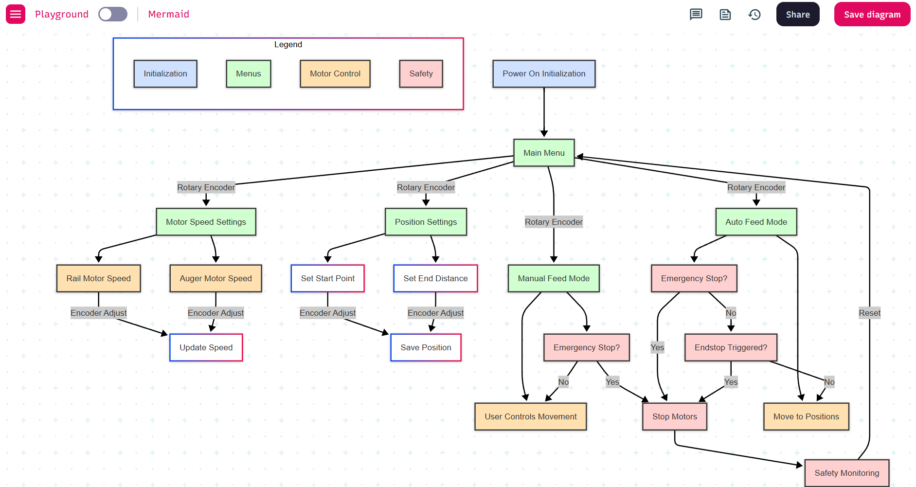
As shown in the flowcharts above, I mapped out the logic of the system step by step to guide the firmware development and make the structure easier to follow.
For the coding, I used the Arduino IDE to write and upload the firmware. The full code is shown below.
📄 Arduino Code for the Linear Autofeeder Project
#include <Wire.h>
#include <LiquidCrystal_I2C.h>
#include <EEPROM.h>
#include <AccelStepper.h>

// LCD Configuration
LiquidCrystal_I2C lcd(0x27, 20, 4); // I2C address 0x27, 20x4 LCD

// Pin Definitions - TESTED AND WORKING
#define RAIL_STEP_PIN D6    // for feeder linear position motor
#define RAIL_DIR_PIN D7     // for feeder linear position motor
#define FEEDER_STEP_PIN D10  // for food extraction motor
#define FEEDER_DIR_PIN D8    // for food extraction motor
#define ENCODER_CLK D2
#define ENCODER_DT D1
#define ENCODER_SW D3
#define ENDSTOP_PIN D0      // for homing limit switch (pulled up)

// Stepper Motor Configuration
AccelStepper railStepper(AccelStepper::DRIVER, RAIL_STEP_PIN, RAIL_DIR_PIN);
AccelStepper feederStepper(AccelStepper::DRIVER, FEEDER_STEP_PIN, FEEDER_DIR_PIN);

// Motor Parameters - SIMPLIFIED 200 SPEED FOR ALL
#define MOTOR_SPEED 200           // All motors: 200 steps/sec
#define MOTOR_ACCELERATION 100    // Acceleration for rail motor
#define STEPS_PER_MM 80           // Steps per millimeter for rail motor
#define FEEDER_FEED_SPEED 200      // Feeder: 200 steps/sec (simplified, reliable)
#define STEPS_PER_REVOLUTION 800  // Both motors: 800 steps = 1 full revolution

// System Constants - UPDATED FOR 800 STEPS/REV
#define MAX_POSITIONS 3
#define MIN_FEED_TIME 1
#define MAX_FEED_TIME 60
#define DEBOUNCE_DELAY 50
#define LONG_PRESS_TIME 2000
#define MAX_RAIL_POSITION 8000    // Increased for 800 steps/rev (was 3000)
#define HOMING_SPEED 100          // Slower homing speed for safety
#define HOMING_TIMEOUT 30000      // Homing timeout in milliseconds

// EEPROM Addresses
#define EEPROM_POSITIONS 0
#define EEPROM_FEED_TIMES 20
#define EEPROM_SETTINGS_SAVED 50
#define EEPROM_HOME_POSITION 60

// System Variables
volatile int encoderPos = 0;
volatile bool encoderChanged = false;
int lastEncoderPos = 0;
bool lastButtonState = HIGH;
unsigned long buttonPressTime = 0;
unsigned long lastDebounceTime = 0;

// Homing Variables
bool isHomed = false;
long homePosition = 0;
bool homingInProgress = false;
unsigned long homingStartTime = 0;

// System State
enum SystemState {
  STARTUP,
  HOMING,
  MAIN_MENU,
  SET_POSITIONS,
  SET_FEED_TIMES,
  FEEDING_MODE,
  RUNNING_CYCLE,
  MANUAL_CONTROL
};

SystemState currentState = STARTUP;
int menuIndex = 0;
int editingPosition = 0;
bool isEditing = false;

// Feeding System Variables - UPDATED DEFAULT POSITIONS
long feedingPositions[MAX_POSITIONS] = {1600, 4000, 6400}; // Updated for 800 steps/rev
int feedingTimes[MAX_POSITIONS] = {5, 5, 5}; // Default feed times in seconds
int currentFeedingPosition = 0;
bool feedingActive = false;
unsigned long feederStartTime = 0;
bool feederRunning = false;
bool railMoving = false;

// Menu Structure
const char* mainMenuItems[] = {
  "1.Start Feeding",
  "2.Set Positions",
  "3.Set Feed Times",
  "4.Manual Control",
  "5.Home System"
};

// Function declarations
void loadSettings();
void saveSettings();
void encoderISR();
void handleEncoder();
void handleButton();
void handleShortPress();
void handleLongPress();
void startHoming();
void handleHoming();
void displayMainMenu();
void selectMenuItem();
void displayHomingRequired();
void displaySetPositions();
void displaySetFeedTimes();
void displayFeedingMode();
void displayManualControl();
void displaySystemInfo();
void handleManualControl();
void handleManualMovement(int delta);
void toggleFeeder();
void startFeedingCycle();
void handleRunningCycle();
void displayFeedingCountdown();
void moveToFeedingPosition(long targetPosition);
void startFeeder();
void stopFeeder();
void stopAllMotors();
void stopFeeding();
void completeFeedingCycle();

void setup() {
  // Initialize serial FIRST
  Serial.begin(9600);
  delay(1000); // Give serial time to initialize
  Serial.println("Animal Feed System Starting...");

  // Initialize LCD
  lcd.init();
  lcd.backlight();
  lcd.clear();

  // Initialize pins AFTER serial is stable
  pinMode(ENCODER_CLK, INPUT_PULLUP);
  pinMode(ENCODER_DT, INPUT_PULLUP);
  pinMode(ENCODER_SW, INPUT_PULLUP);
  pinMode(ENDSTOP_PIN, INPUT_PULLUP);

  // Initialize motor pins
  pinMode(RAIL_STEP_PIN, OUTPUT);
  pinMode(RAIL_DIR_PIN, OUTPUT);
  pinMode(FEEDER_STEP_PIN, OUTPUT);
  pinMode(FEEDER_DIR_PIN, OUTPUT);

  // Set initial states - ALL LOW
  digitalWrite(RAIL_STEP_PIN, LOW);
  digitalWrite(RAIL_DIR_PIN, LOW);
  digitalWrite(FEEDER_STEP_PIN, LOW);
  digitalWrite(FEEDER_DIR_PIN, LOW);

  // Attach interrupts for encoder
  attachInterrupt(digitalPinToInterrupt(ENCODER_CLK), encoderISR, FALLING);

  // Initialize stepper motors - ALL 200 SPEED
  railStepper.setMaxSpeed(MOTOR_SPEED);      // 200 max
  railStepper.setAcceleration(MOTOR_ACCELERATION);

  feederStepper.setMaxSpeed(FEEDER_FEED_SPEED); // 200 max
  feederStepper.setAcceleration(MOTOR_ACCELERATION);

  Serial.println("Motors configured - ALL at 200 steps/sec");

  // Load settings from EEPROM
  loadSettings();

  // Display welcome message
  lcd.setCursor(0, 0);
  lcd.print("Animal Feed System");
  lcd.setCursor(0, 1);
  lcd.print("SIMPLIFIED - 200sps");
  lcd.setCursor(0, 2);
  lcd.print("Focus: MOTOR SPIN");
  lcd.setCursor(0, 3);
  lcd.print("Initializing...");
  delay(3000);

  // Start homing sequence
  currentState = HOMING;
  startHoming();

  Serial.println("Setup complete - Starting homing");
}

void loop() {

  handleEncoder();
  handleButton();

  //...
13. Linear Autofeeder Quick Start Guide
What is the Linear Autofeeder?
The Linear Autofeeder is an automatic feeding system that travels along a rail to feed your animals at multiple locations. Think of it as a smart robot that moves food where it's needed, when it's needed without you having to be there.
What it does:
- Moves automatically to 3 different feeding locations
- Dispenses precise amounts of food at each spot
- Runs on a schedule you set up once
- Remembers your settings even after power outages
- Works reliably day after day with minimal maintenance
How the System Works
The Simple Process:
- Homing: System finds its starting position automatically
- Programming: You set where to feed and for how long
- Automatic Operation: System runs feeding cycles on its own
- Repeat: Continues reliably until you change settings
- Rail System: The track that the feeder travels along
- Control Box: LCD screen and dial for programming
- Motors: Move the system and dispense food
- Sensors: Know when system reaches each position
Quick Reference
Dial Actions Control Dial (Encoder):
| Action | What It Does |
|---|---|
| TURN | Navigate menus, adjust values, move system |
| PRESS | Select option, confirm choice, toggle feeder |
| HOLD | Go back, exit to main menu, emergency stop |
Screen Symbols:
| Symbol | Meaning |
|---|---|
| > | Currently selected menu item |
| [5s] | Value being edited (brackets) |
| H:OK | System is homed and ready |
| H:NO | System needs homing first |
| LIVE | System moving in real-time |
| MOVE | Motor currently running |
| STOP | Motor has stopped |
Common Screens:
- Main Menu = Choose what to do
- Set Positions = Program where to feed
- Set Feed Times = Program how long to feed
- Feeding Mode = Ready to start cycle
- Manual Control = Test system manually
Complete Setup Sequence
Your First Time Setup:
Step 1: Power On
- System automatically homes
- Wait for main menu
Step 2: Set Position 1
- TURN → Select "2.Set Positions"
- PRESS → Enter position setup
- PRESS → Start editing Pos 1
- TURN → Watch system move to desired location
- PRESS → Save position
Step 3: Set Position 2
- TURN → Select Pos 2
- PRESS → Start editing
- TURN → Move to second feeding location
- PRESS → Save position
Step 4: Set Position 3
- TURN → Select Pos 3
- PRESS → Start editing
- TURN → Move to third feeding location
- PRESS → Save position
- HOLD → Return to main menu
Step 5: Set Feed Times
- TURN → Select "3.Set Feed Times"
- PRESS → Enter time setup
- For each position:
- PRESS → Start editing
- TURN → Adjust seconds (5-15 is good to start)
- PRESS → Save time
- HOLD → Return to main menu
Step 6: Start Feeding
- TURN → Select "1.Start Feeding"
- PRESS → Enter feeding mode
- PRESS → Start automatic cycle
- Watch it work!
Daily Operation
To Feed Your Animals:
- TURN dial → Select "Start Feeding"
- PRESS dial → Enter feeding mode
- PRESS dial → Begin cycle
- Walk away → System runs automatically
Emergency Stop:
- PRESS dial anytime during feeding = Immediate stop
- HOLD dial = Return to main menu
14. The project testing
Before assembling all the parts, I tested the code separately to ensure each function worked correctly. The video above shows the code testing process in action.
After testing the code, I assembled all the mechanical and electronic parts to see how the complete system would work together. I was pleased to find that the Linear Autofeeder functioned successfully as planned.
15. Design files
- download file (KiCad projects and SVG files)
- download file (assembly design)
- download file (leg-1)
- download file (leg-1, DXF)
- download file (leg-2)
- download file (leg-2, DXF)
- download file (auger)
- download file (auger, STL)
- download file (hooper)
- download file (hooper, STL)
- download file (carriage)
- download file (carriage, STL)