Applications and implications
Individual assignment:
- Plan a final project masterpiece that integrates the range of units covered, answering:
- What will it do?
- Who's done what beforehand?
- What sources will you use?
- What will you design?
- What materials and components will be used?
- Where will come from?
- How much will they cost?
- What parts and systems will be made?
- What processes will be used?
- What questions need to be answered?
- How will it be evaluated?
The project ecompases the design and production of the conversion kit for bike which will be used as a mode of transport to reduce traffic jame and preserving the climate, as it will reduce the carbon footprint from fuel-powered cars.
- Project Overview
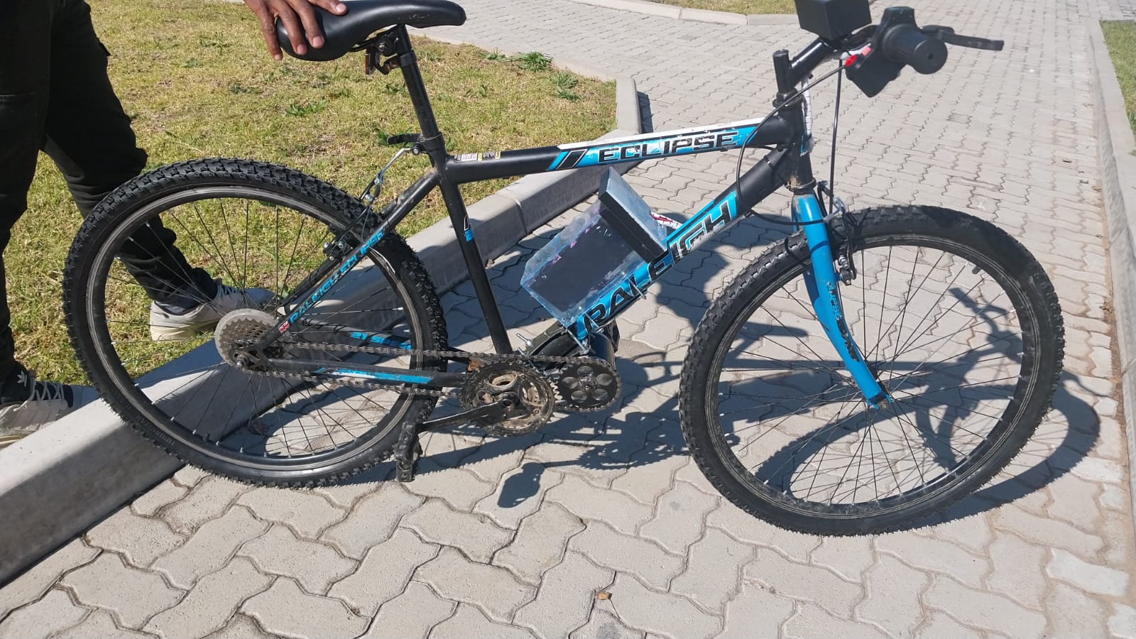
• Build a full conversion kit for the motorcycle.
• Design and build circuit board that include voltage regulator for microcontroller and some components that required small voltage.
• Use microcontroller to process throttle input to control the motor speed, and display battery state of charge.
• Display throttle percentage, and fault status on an OLED.
• Enable Bluetooth connectivity for real-time data monitoring via a smartphone app (optional).
• Design 3D-printed display and circuit board enclosure for handlebar mounting.
• Implement fault detection (e.g., MOSFET temperature errors, low battery) on the display.
Motor Controller PCB for Final Project Masterpiece
What Will It Do?
- Read throttle input to controlled motor speed
- Regulate 24V to 5V for powering microcontroller.
- Send monitoring data to display for real time monitoring.
- Read MOSFET temperature for overheating protection
- Bafang, Kelly, and VESC offer commercial motor controllers.
- Open-source projects like VESC and SimpleFOC provide firmware and hardware design examples.
- Makers on GitHub and YouTube have built brushed/BLDC motor drivers with Arduino and STM32.
- Datasheets: NE555G, 2SC5200, LM7805, etc.
- KiCad documentation for PCB design
- IEEE papers and YouTube for gate driver design, current control
- VESC firmware, open-source controller schematics, Elcircuits
- Fab Academy tutorials on electronics production, 3D modeling
- Custom 1-layer motor controller PCB
- 3D-printed or CNC-cut motor mount and battery enclosure
- Monitoring display box Materials and Components
- Custom PCB (motor driver, microcontroller pcb)
- firmware (monitoring, sensor feedback)
- Enclosure (3D printed or CNC-milled)
- Motor mount
- Will it use PWM for motor speed control?
- Will it support both brushed and BLDC motors?
- Can the microcontroller handle real-time monitoring and control?
- What kind of failsafe and recovery strategy will be implemented?
-
✓ Designed the Motor Controller Schematic
• Utilized KiCad to create a complete schematic, including IRFZ44, resistors, IN4007 diode, throttle input conditioning circuitry, brake switch interface, DC‐DC 24->5 V converter, microcontroller (Xiao RP2040), and connectors (battery, 3‐pin for throttle,brake,display, pins for the sensors).
-
✓ PCB Layout Validation & Fabrication
• Converted schematic to PCB layout in KiCad, paid particular attention to high‐current traces (10 mm width), thermal relief for MOSFETs, and distance between high‐power nets to prevent arcing.
• Routed ground planes, added thermal vias under MOSFET pads, and created silkscreen annotations for component placement.
• Exported Gerber and drill files, and submitted to PCB fabrication service (1 layer copper). -
✓ PCB Assembly
• After PCB production, hand‐soldered MOSFETs, DC‐DC converter module, microcontroller, and all (resistors, capacitors).
• Confirmed solder quality with X‐ray refracted light, tested continuity of power rails and gate‐drive nets. -
✓ Initial Firmware Development
• Wrote C++ firmware on Arduino IDE targeting XIAO RP2040. – ADC reading of throttle (0–5 V) with 10‐bit resolution, mapped to 8‐bit PWM duty cycle.
– Brake switch interrupt (pin change) to override throttle and cut PWM instantly.
– UART serial logging (9600 baud) for real‐time telemetry: throttle value, current sense reading, temperature reading, battery voltage reading.
-
✓ Static Bench Testing
• Connected PCB to a lab power supply (24 V @ 5 A limit), resistive load to simulate motor current draw.
• Verified that as throttle turns from 0 to 5 V, PWM duty smoothly increases and output voltage follows setpoint.
• Measured current by reading voltage drop on 0.01 Ω sense resistor through differential amplifier → ADC; confirmed linear scaling. -
✓ Overload Protection
• Calibrated the op‐amp‐based current sensor: measured known loads, adjusted gain resistors to map 0–30 A to 0–5 V range.
• Added software limit: if sensed current > 25 A for > 100 ms, cut PWM to 0 and issue fault code over serial. Confirmed with short‐circuit test (~5 Ω load) that fault triggers as expected. -
✓ Connect OLED display and battery
• Connect and enclosures the display in the 3D printed screen enclosure.
• connect battery cells in series and parallel to achieve required voltage (24V). -
✓ Fine-Tune PWM Frequency & Duty Cycle Modulation
• Evaluate effect of different PWM frequencies (10 kHz–50 kHz) on motor noise and efficiency. Adjust Timer1 prescaler and TOP value in firmware.
• Implement a two‐stage current limit: soft limit at 20 A (reduce duty linearly) and hard limit at 30 A (trigger fault). -
✓ Real‐World Motor & Battery Testing
• Connect PCB to an actual 250 W hub motor and 24V Li‐ion pack.
• Record performance metrics: acceleration response, steady‐state speed under various loads, current draw at full throttle, and temperature rise over 10 minutes of constant duty. -
✓ Throttle Response Curve Improvement
• Implement software mapping (e.g., exponential curve) so that initial throttle movements result in gentle acceleration and higher turns yield steeper power. Add a configurable dead zone (0–10% throttle ignored) to avoid jerky starts.
-
✓ Enclosure Design & Packaging
• Use CAD software (SolidWorks) to model a custom plastic enclosure that houses the PCB, DC‐DC converter, and connectors.
• Provide ventilation/heat sinks for MOSFETs, rubber gaskets for waterproofing, and mounting flanges to bolt the enclosure to the bike frame. 3D print a prototype for fit validation. -
✓ Complete Documentation & Demo Video
• Compile all photos, CAD screenshots, test logs, and firmware code into a coherent project report and step-by-step assembly guide.
• Capture a 2–3 minute video showing the fully assembled e-bike running outdoors: demonstrate acceleration, braking. Narrate the key technical points and safety features. -
✓ Final Presentation Slides & video
• Prepare a concise slide deck (10–12 slides) summarizing problem statement, system architecture, design challenges, test results, final performance, and next steps.
• Design an 24×36″ poster for showcasing at symposiums or maker fairs. Include diagrams, charts (e.g., efficiency vs. load), and key takeaways. -
⧗ Temperature Sensing & Thermal Protection
• Position negative‐temperature‐coefficient (NTC) thermistors on MOSFET heatsink or inside battery pack. Add conditioning circuitry (pull‐up resistor + lowpass RC) to ADC inputs.
• In firmware, continuously monitor temperature; if > 70 °C, ramp down PWM; if > 80 °C, cut off and flag overheat. - Throttle -> PWM Mapping: The firmware’s linear mapping of throttle voltage (0–5 V) to PWM duty (0–100%) is stable and reproducible. No visible jitter at low speeds.
- MOSFET Switching: IRFP44 switch cleanly at 20 kHz with minimal switching losses (measured ~2 W per MOSFET at 15 A load).
- Serial Telemetry: Real‐time data (throttle, current, temperature, voltage) prints reliably to terminal at 9600 baud. Useful for debugging and logging.
- Regenerative Braking Implementation:
• Can we feed regenerated energy back into the battery safely without a buck‐boost converter?
• Do we need a dedicated “reverse” driver stage or can we use the same MOSFET half‐bridge?
• What charging profile and protection is required for Li-ion cells during regeneration? - Battery Protection (Fuse vs. Circuit Breaker):
• Should we add a high‐current auto-resetting polyfuse on the main 24V line?
• Or is a mechanical circuit breaker with a manual reset preferable?
• How to balance safety, reliability, and cost? - BLE Mobile App for Data Logging:
• Would real-time app readouts of speed, battery state‐of‐charge, and fault codes add significant user value?
• Does the added complexity of BLE radio (e.g., ESP32) justify the benefits compared to UART-to-USB logging?
| Component | Type | Source | Est. Cost ($) |
|---|---|---|---|
| Power Transistor | 2SC5200 | Communica (Pty) Ltd South Africa | 0.85 |
| Voltage Regulator IC | LM7805 | Communica (Pty) Ltd South Africa | 0.38 |
| Temperature Sensors | 24V | Nyerekatech | 3.46 |
| Microcontroller | Seeed XIAO RP2040 | Nyerekatech | 7.62 |
| Capacitors | Bulk X 10 | Communica (Pty) Ltd South Africa | 2.5 |
| Resistors/Diodes | Assorted pack | Communica (Pty) Ltd South Africa | 0.66 |
| PCB | Custom fab (1-layer, FR4 copper) | From inventory | |
| Heat Sink | Aluminum | Scrap | |
| Battery | 3.7V X 18 Li-ion | Takealot South Africa | 41.04 |
| Display | 16x2 I2C / OLE | Nyerekatech | 6.23 |
| Motor | 24V, 20A, 300rpm | Amazon.com | 38.99 |
| Throttle | 5V output signal | Amazon.com | 14.99 |
| Unit | Process Used |
|---|---|
| 2D/3D Design | Enclosure and mount in SolidWorks |
| Additive Fabrication | 3D printing for enclosures |
| Subtractive Fabrication | CNC milling for metal sheet mount |
| Electronics Design | KiCad schematic + PCB layout |
| Production | PCB milling |
| Embedded Programming | C++ with Arduino IDE (ESP32C3) |
| Interfacing | Throttle, sensors, LCD |
| System Integration | Full wiring and mechanical assembly |
| Evaluation Metric | Criteria |
|---|---|
| Functional Testing | Smooth throttle control, no overheating |
| Safety | Current limits enforced |
| Design Integration | Clean, compact layout; 3D-printed case |
| Embedded Logic | Sensor response, overvoltage/overtemp logic |
| Aesthetics and Packaging | Finished housing and mounted connectors |
| Documentation | Full Bill of material, schematics, firmaware, photos, videos |
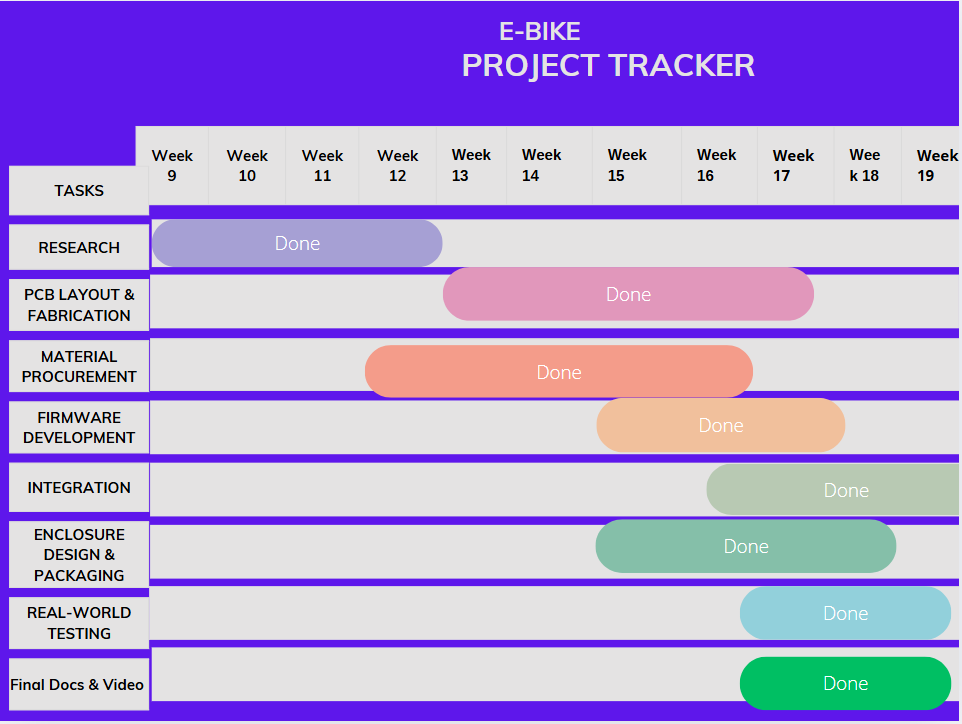
The following section catalogs all tasks completed to date, tasks still pending, current system status, unresolved questions, and an estimated timeline. This helps keep the project on schedule and provides transparency for collaborators or evaluators.
Completed Tasks
- >
| Date | Task |
|---|---|
| June 3-4 | Print custom enclosure in CAD: include boss features for mounting, heat‐sink locations, cable gland holes, and ventilation slots. 3D print a prototype in ABS for test fitting onto the bicycle frame. |
| June | Perform full‐load testing on a 250W hub motor with 24V 10 Ah battery. Record current draw, speed vs. throttle curve, and temperature rise over 10 minute continuous operation. Document anomalies (e.g., motor cogging, unexpected oscillations). |
| June | Finalize firmware version 1.1: incorporate temperature‐based PWM derating algorithm, implement soft‐start routine (ramp PWM from 0% to requested duty over 0.5 s), and adjust throttle dead zone. Lock code for release. |
| June | Film and edit a 2–3 minute demonstration video: intro with system overview, animated block diagram overlaid, live footage of e‐bike accelerating, regenerative braking (if working), and narration describing key features. Compress and upload to YouTube. |
| June | Complete online documentation: update GitHub repository with final schematics, PCB layout, source code, CAD/STL files for enclosure, BOM, and “how to build” guide. Publish project webpage with embedded video. |
| June | Finalize slides and poster: prepare PDF slide deck (10–12 slides) for symposium talk and design a 24″×36″ poster with diagrams, photos, test results (e.g., graphs of current vs. time, efficiency curves), and key lessons. Submit all materials to course coordinator. |