Individual Assignment
Design, lasercut, and document a parametric construction kit, accounting for the lasercutter kerf, which can be assembled in multiple ways.
Cut something on the vinyl cutter.
Parametric Design
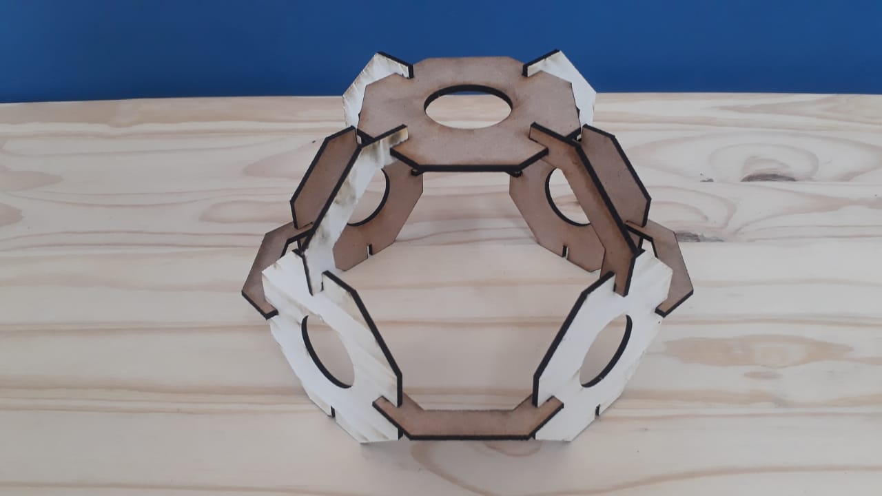
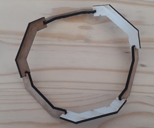
This section shows how a parametric design made using SolidWorks. This object can be assembled in different shapes.
How the design is made.
- Creating new project
-Open the SolidWorks application
-Click the part to create the new project.
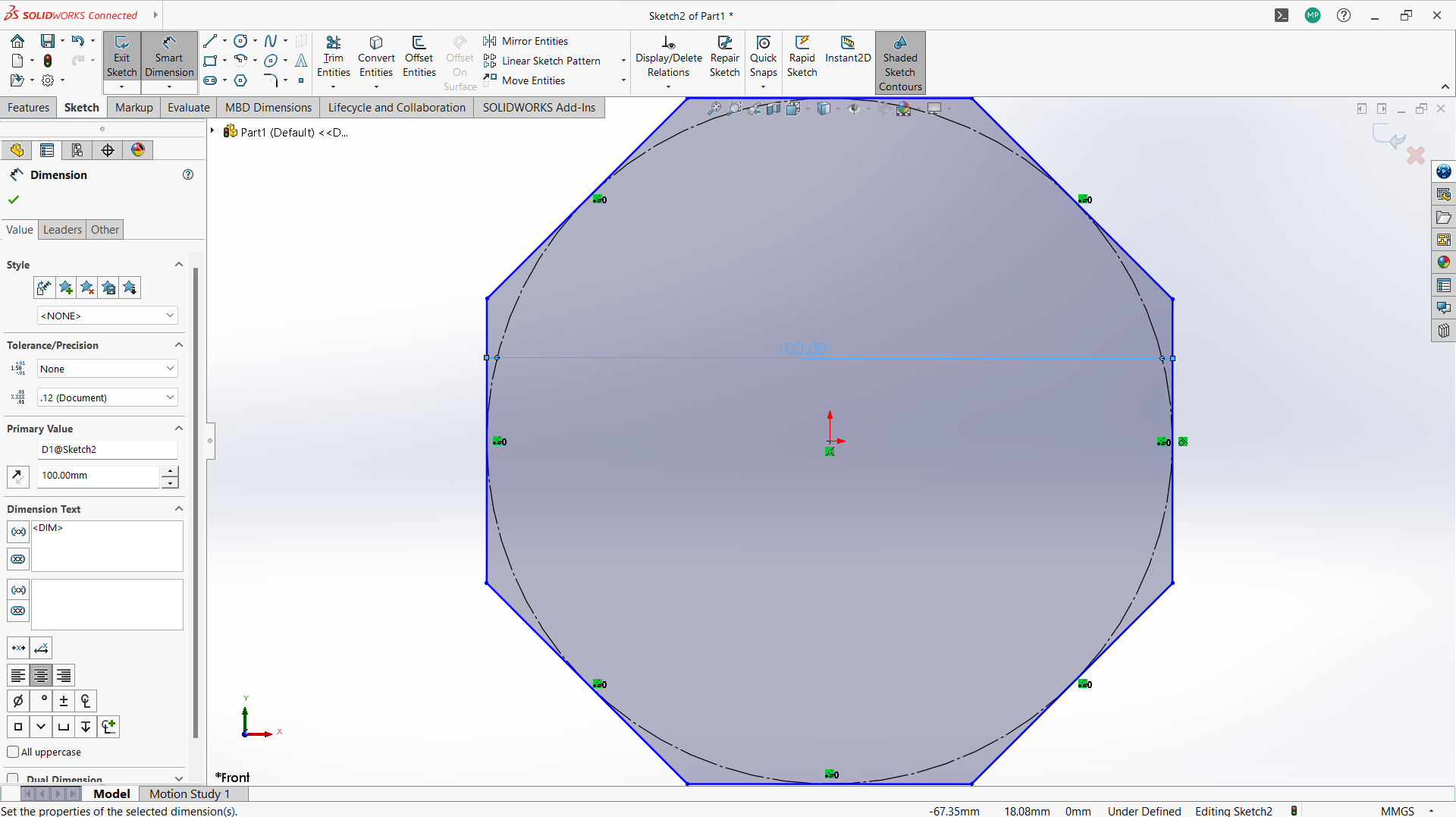
-Created new sketch on the front plan.
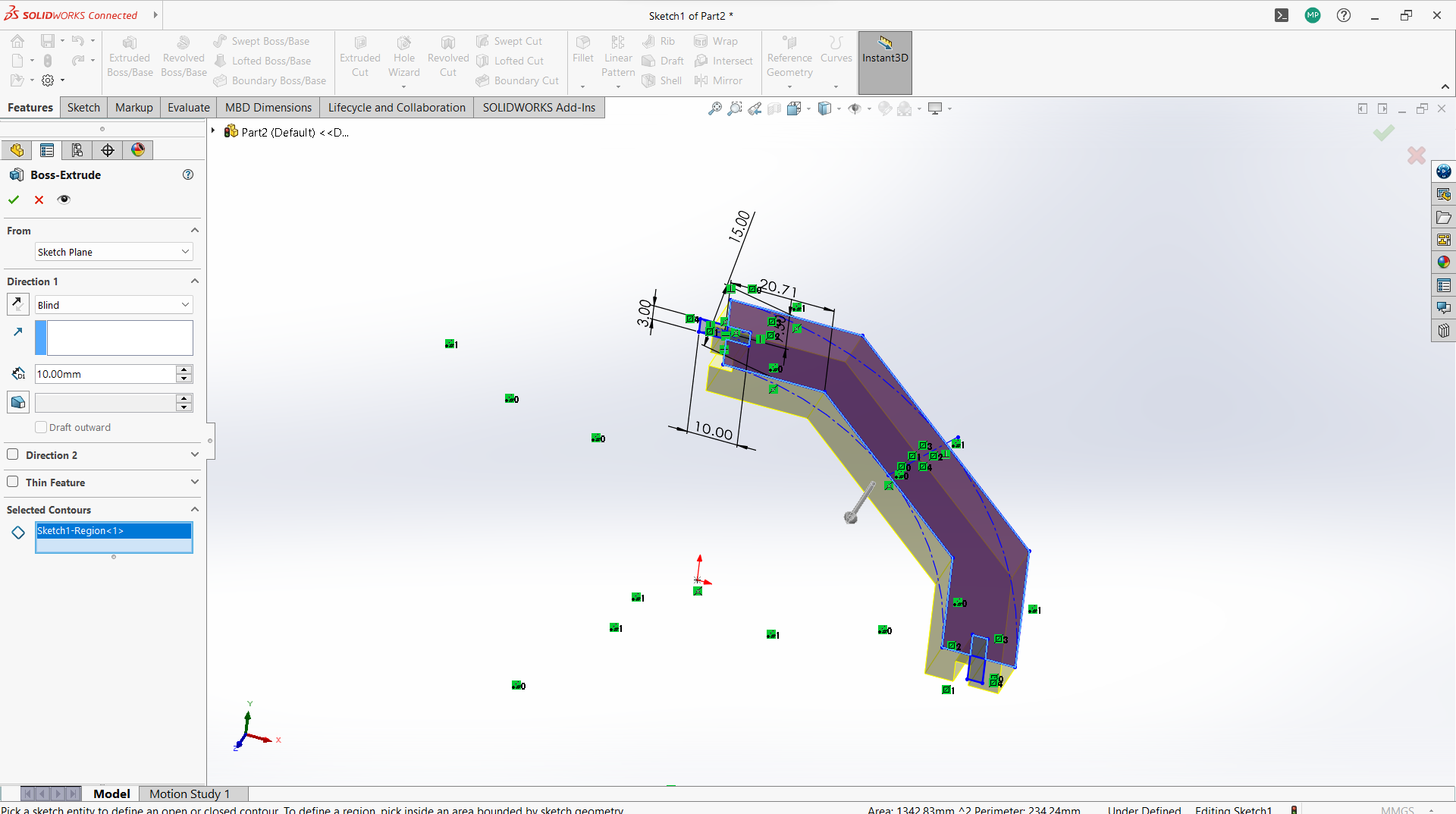
- Creating parts of the design
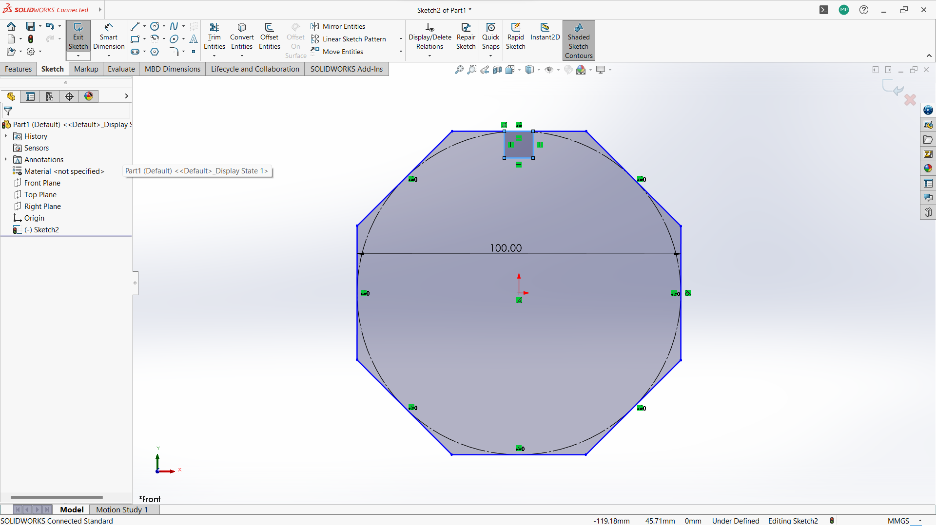
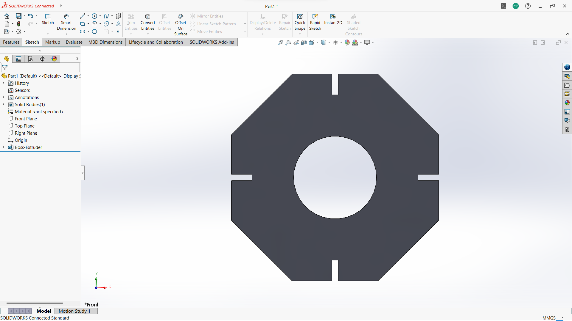
- Create polygon using polygon tool under sketch.
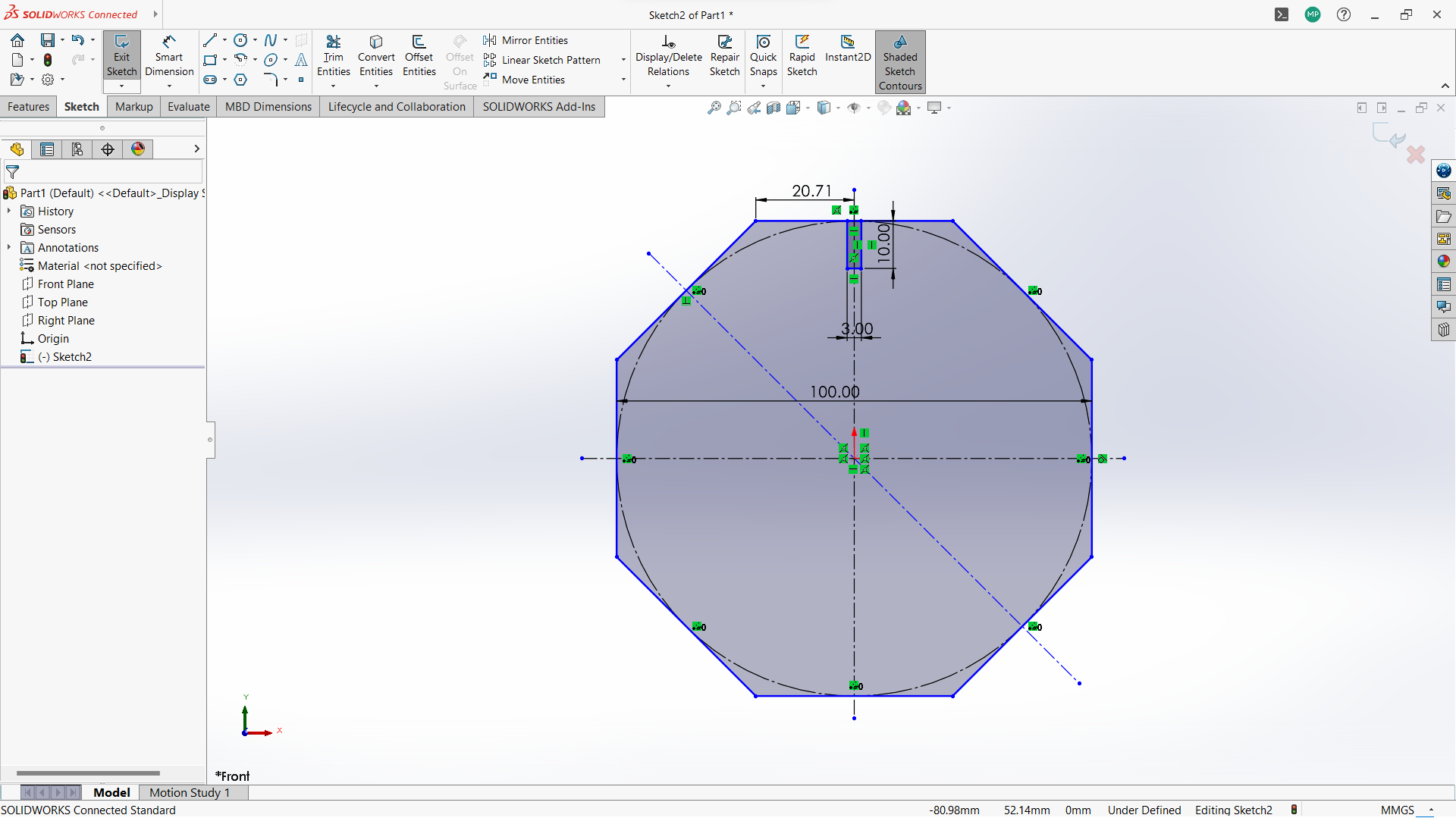
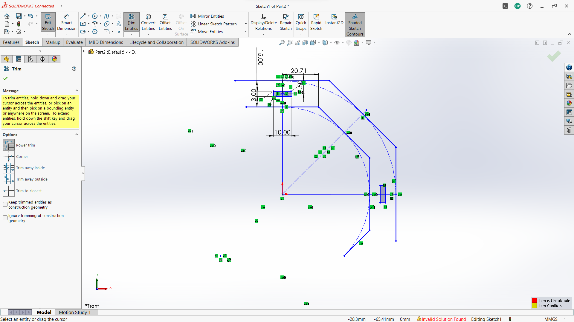
-Created a rectangle to create a joint, 10mm depth and width 3mm to allow 3mm wood to fit in.
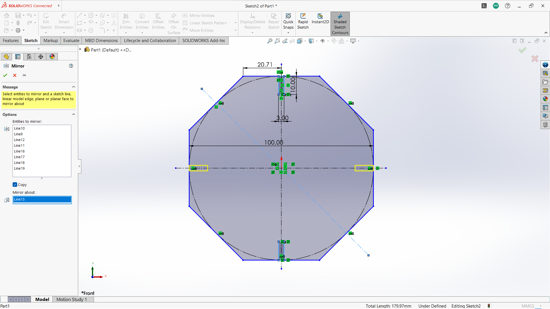
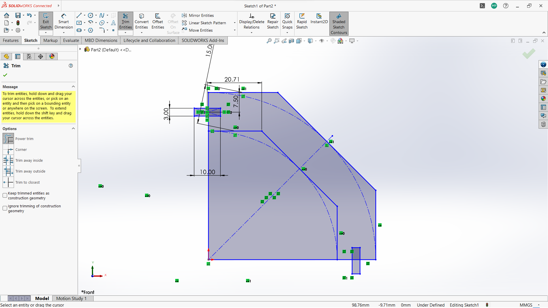
-Used trim entity tool to cut the top part of the rectangle to form one object with polygon.
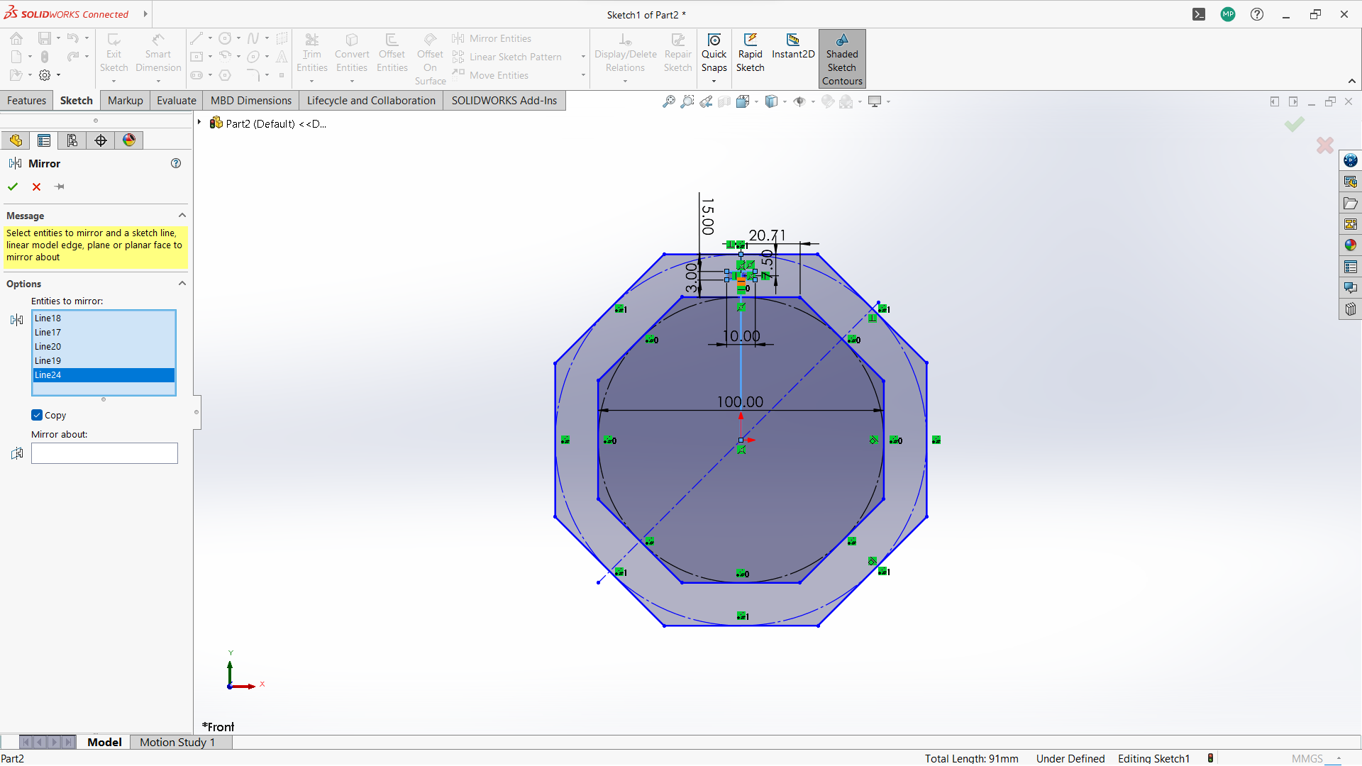
-Use circular linear pattern tool to duplicate the joints in a 90 degrees pattern.
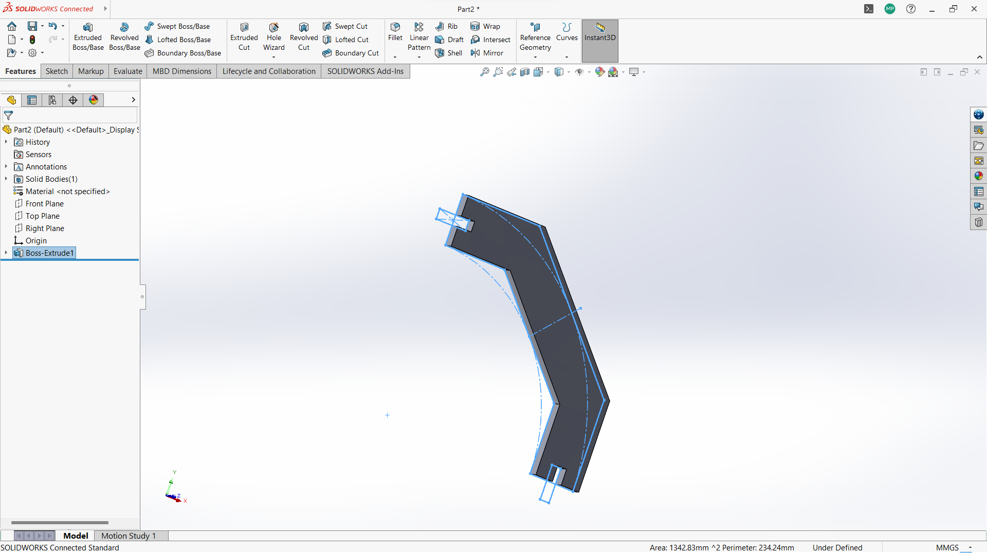
-Used extrude tool to make 3mm thickness of the sketch part.
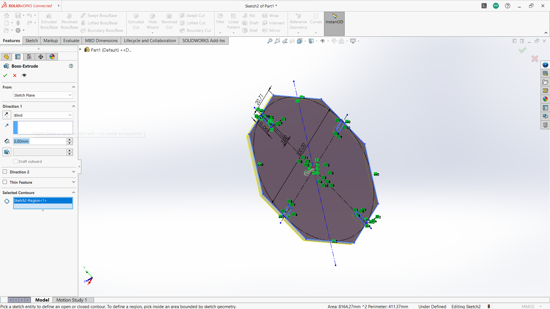
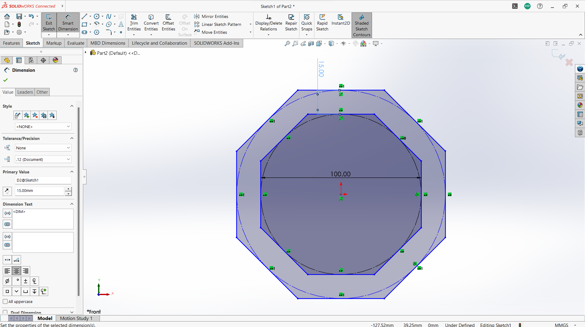
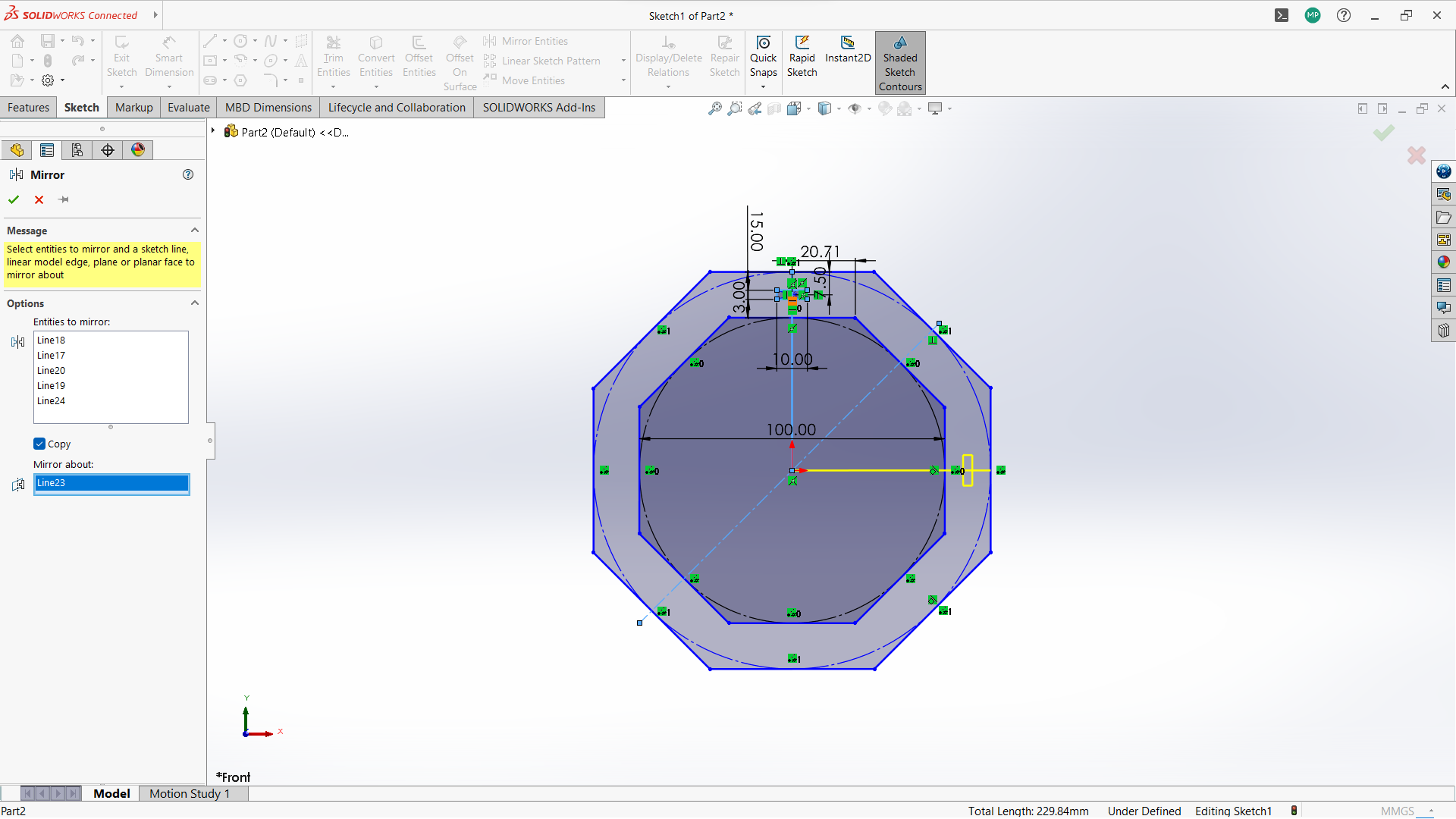
Making connecting cross bar.
-Create two polygon using polygon tool under sketch, small inside the big one.
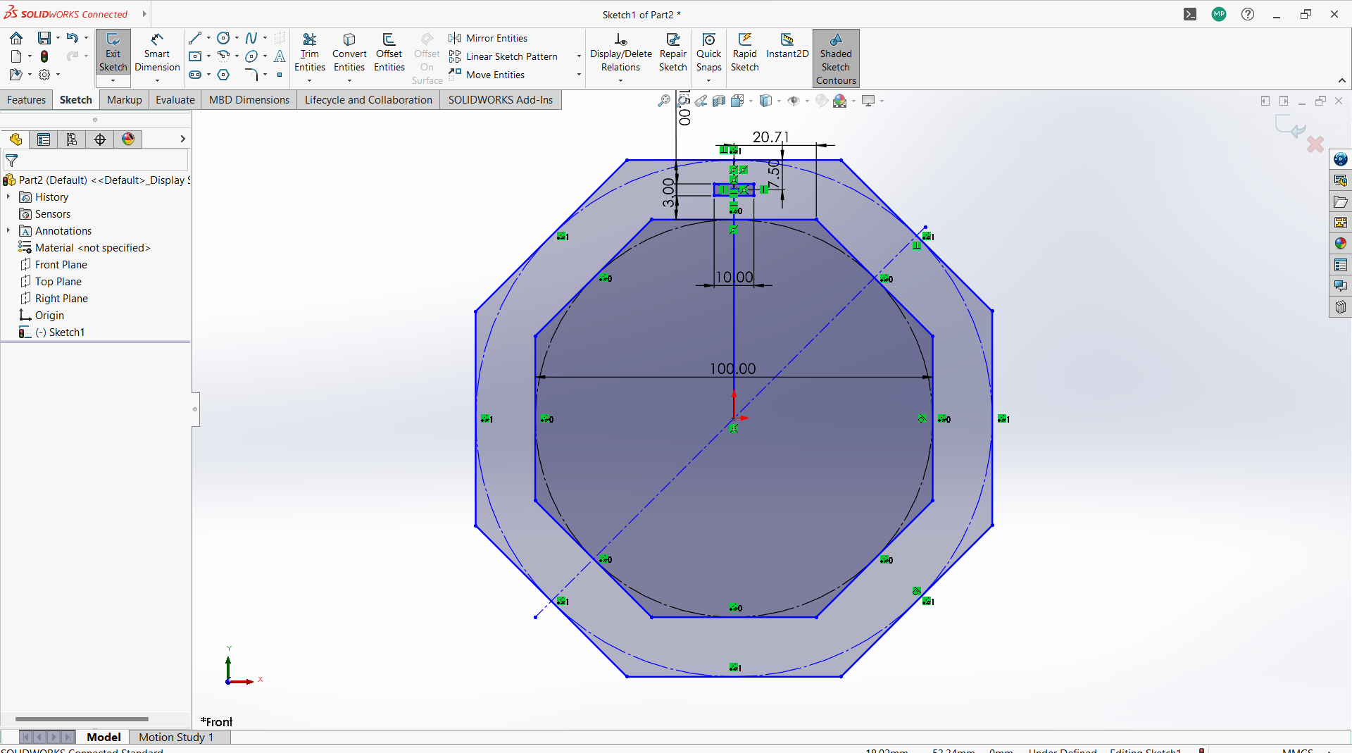
-Created a rectangle to create a joint, 10mm depth and width 3mm to allow 3mm wood to fit in.
-Use circular linear pattern tool to duplicate the joints in a 90 degrees pattern to make two joints both sides.
-Used trim entity tool to cut the unwanted lines to form one one object with polygon.
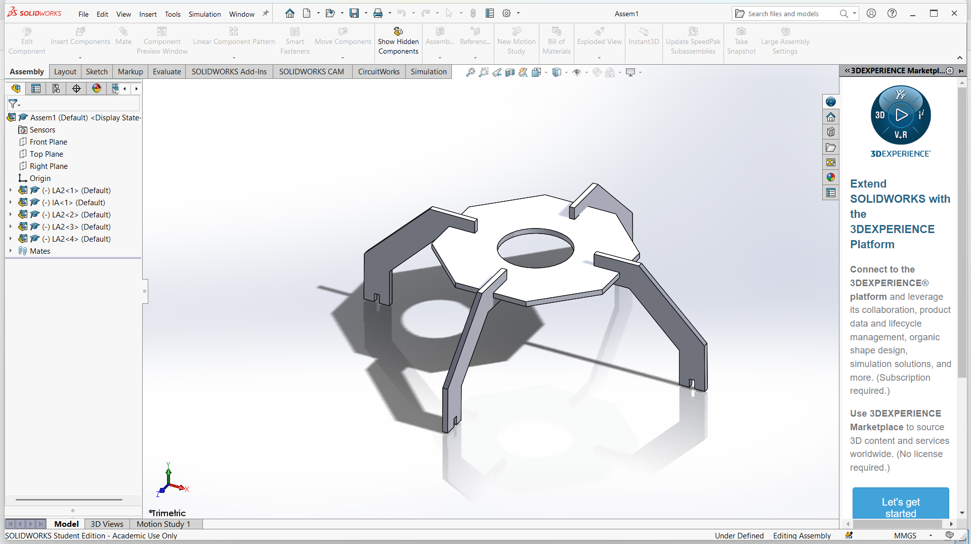
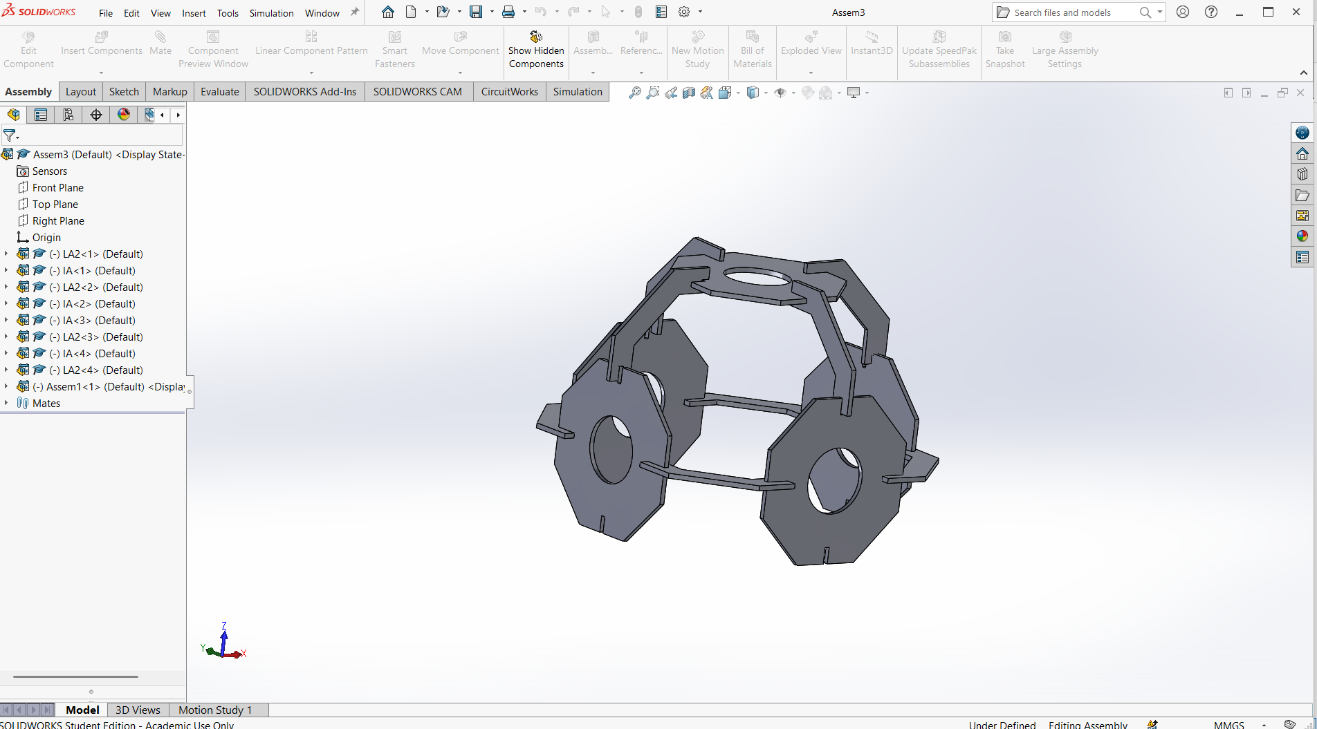
Assembling parts from designs.
In SolidWorks, an assembly is a file type (.SLDASM) that allows you to bring together multiple parts (.SLDPRT) to create a functional product or mechanism. Assemblies let you define how parts fit and move relative to each other using mates, and they can include sub-assemblies (assemblies inside assemblies).
Basic Steps to Create an Assembly in SolidWorks 1. Start a New Assembly- Go to File > New > Assembly.
- Choose your template and click OK.
- Click Insert Components from the CommandManager or go to Insert > Component > Existing Part/Assembly.
- Browse to and select the part(s) you want to insert.
- Click to place the component into the graphics area.
Mates define how components are aligned and connected. Use Mate from the Assembly toolbar.
Common mates:
- Coincident: Faces, edges, or planes touch each other.
- Concentric: Cylindrical features share the same center.
- Distance: Sets a fixed gap between components.
- Angle: Fixes an angle between parts.
- Use the Move Component or Rotate Component tools to adjust parts before mating.
- Dynamic dragging helps to test motion and find conflicts.
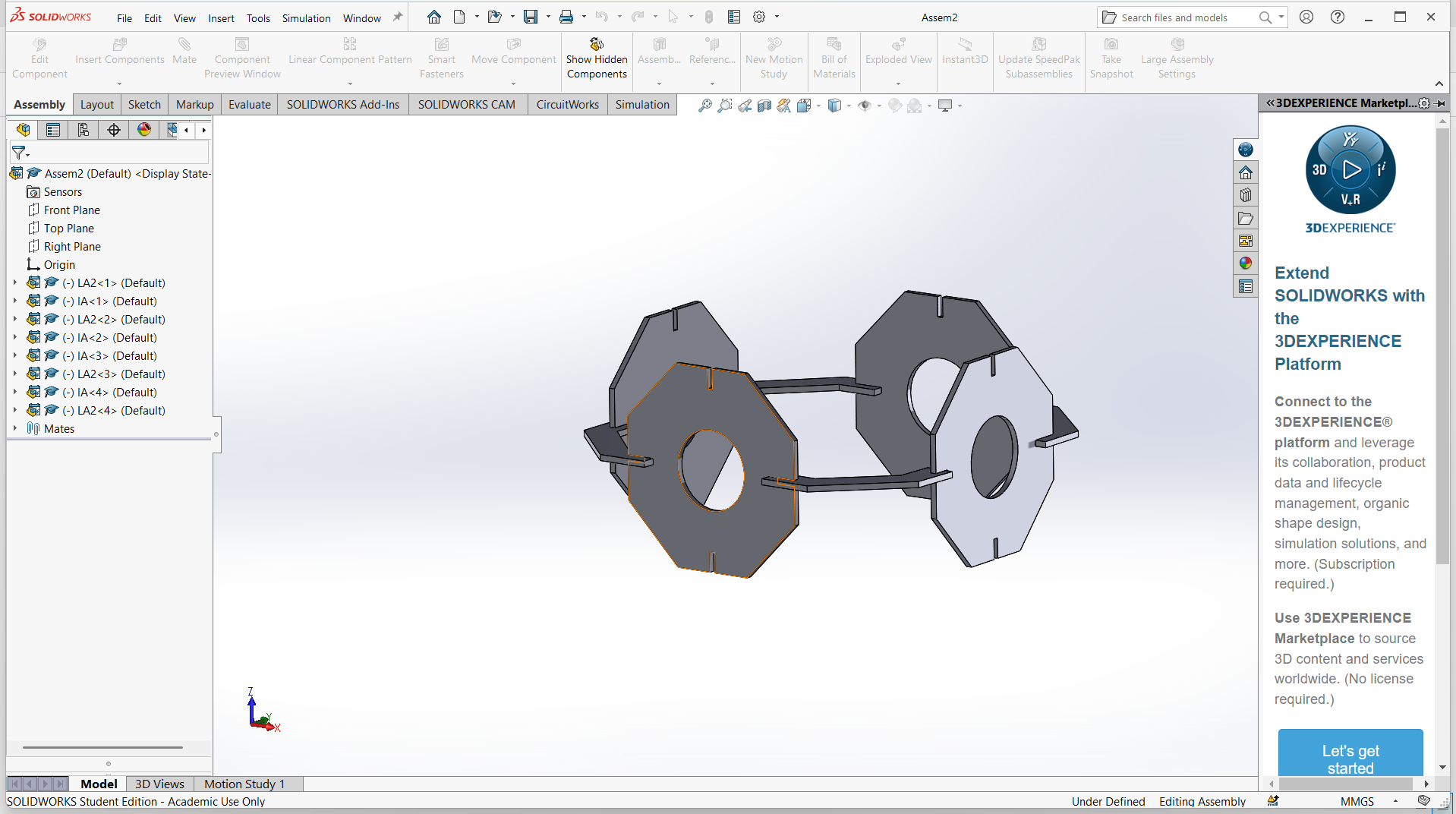
- You can create an assembly from parts, save it, and insert it into another assembly.
- This helps manage complexity and organize your design.
-Export the final object for laser cutting.
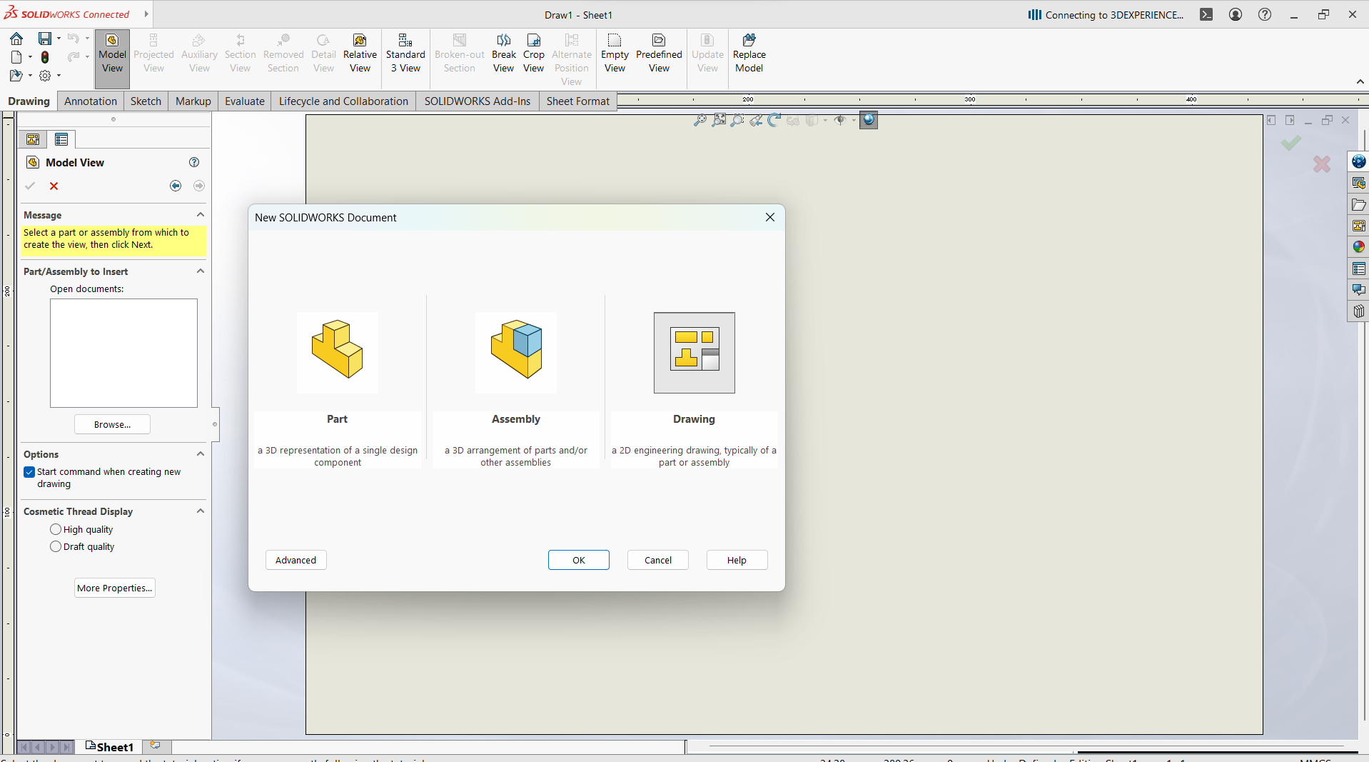
Open Export DXF from a Drawing View Best for dimensioned or projection views. Steps to follow- Create a Drawing:
- Go to File > New > Drawing
- Select a drawing
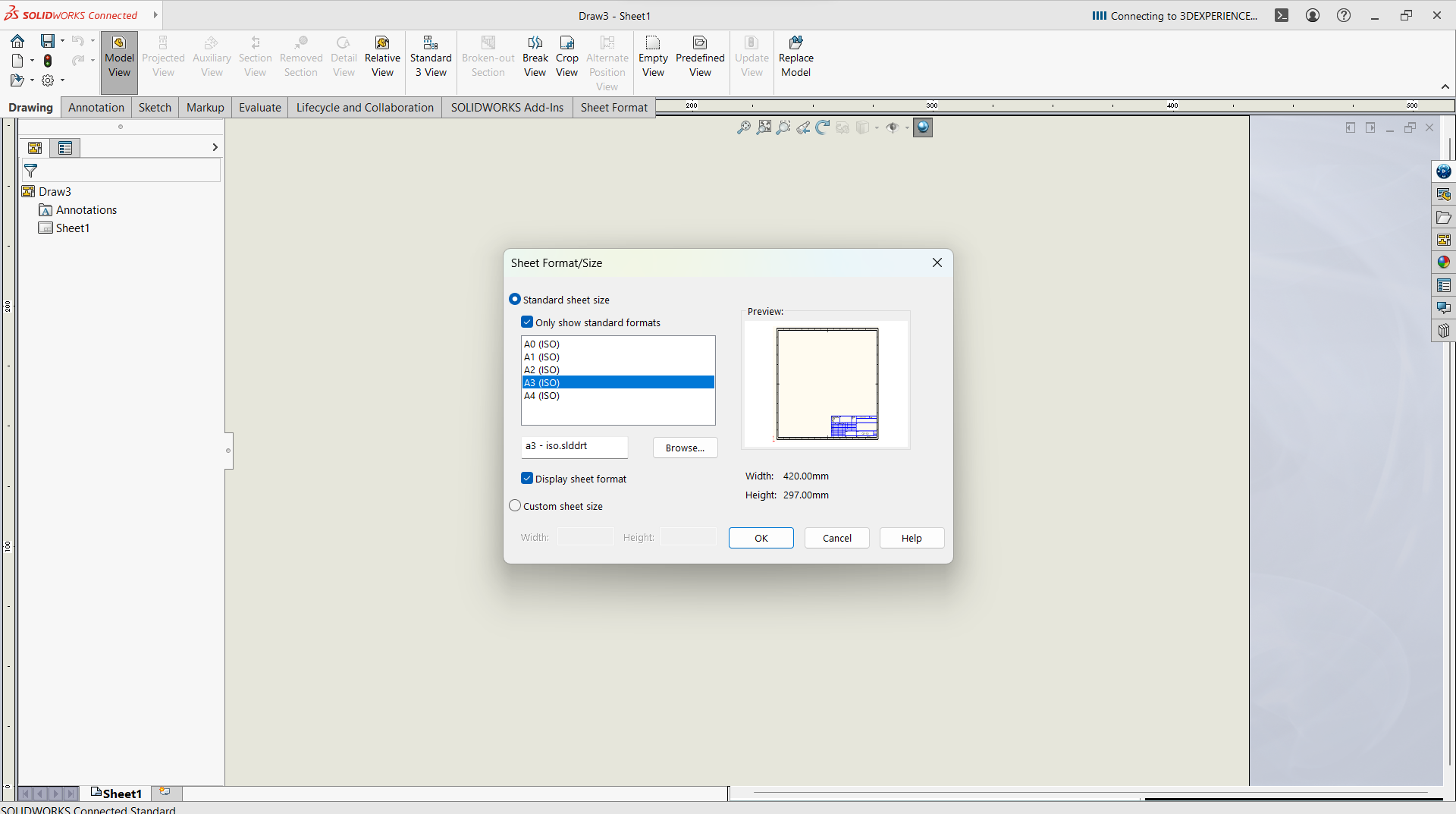
- Select sheet format/size
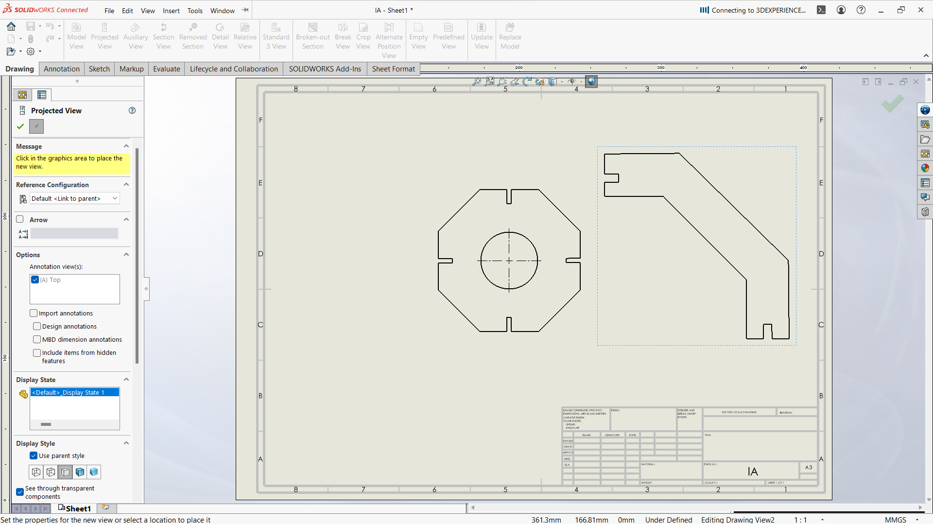
- Go to view model, then browse to select the parts
- Drop on the work space of the sheet
- Save the Drawing as DXF:
- Go to File > Save As > DXF
- Choose what views or sheets to include
- Click Save

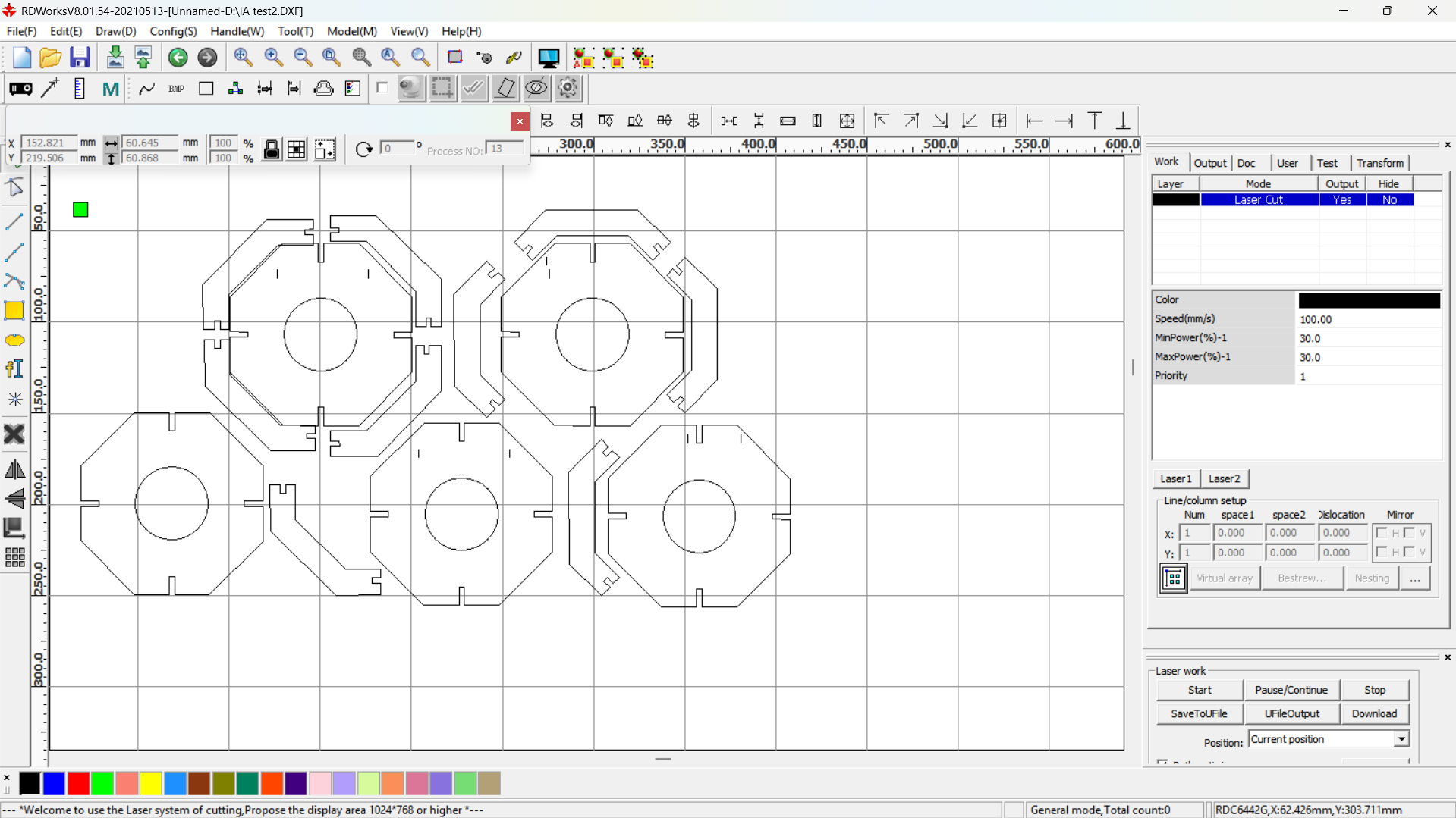
- Making toolpath
I have used RDWorks software downloaded from RDWorks V8 and installed on windows using default settings.
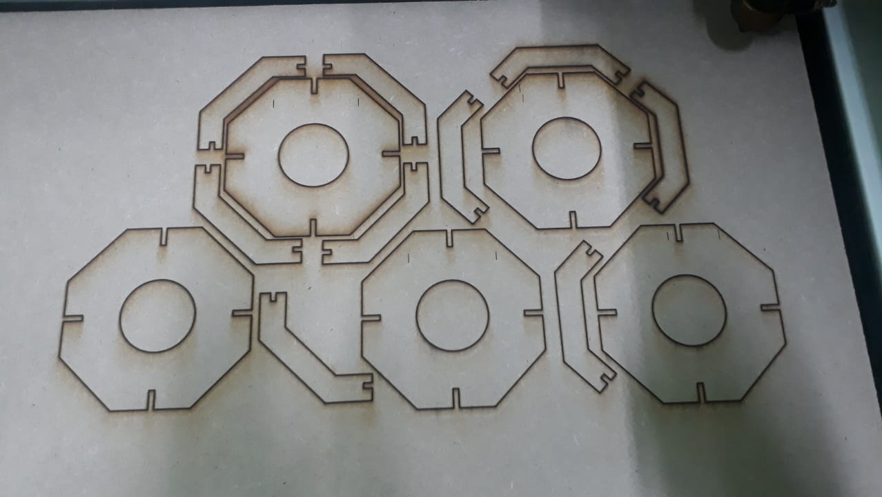
I imported the DXF files into RDWorks software to prepare it for CO2 Laser cutting. The parts are duplicated to the number required.
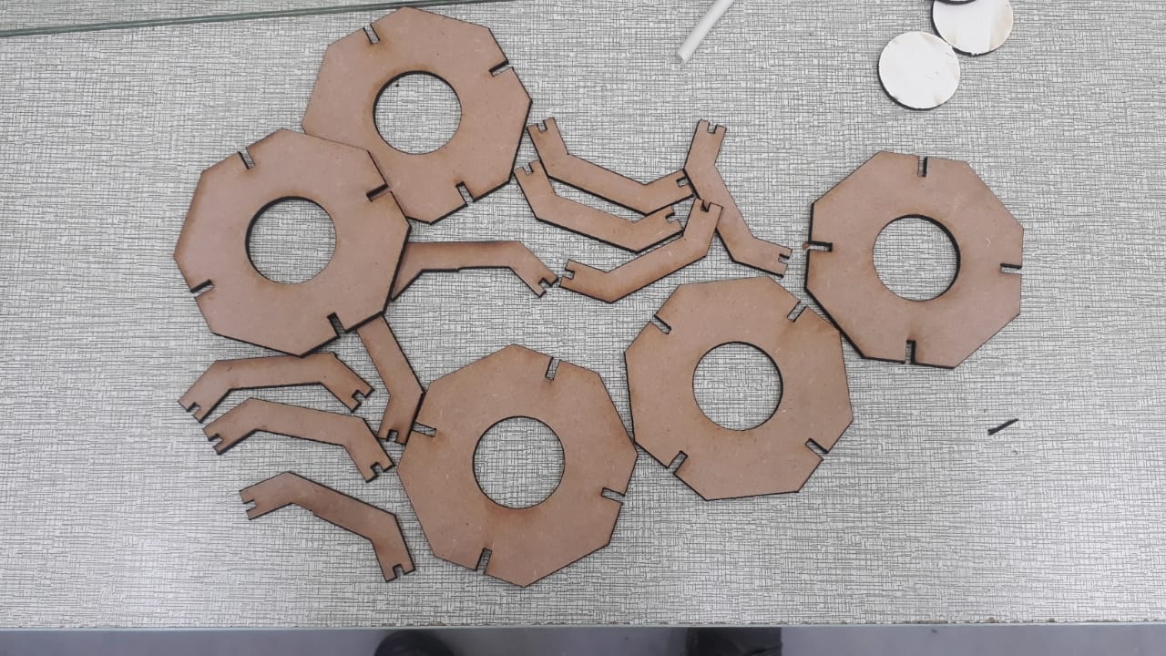
After the toolpath is completed, the print job sent to the laser to start cutting. - Assembling after laser cut
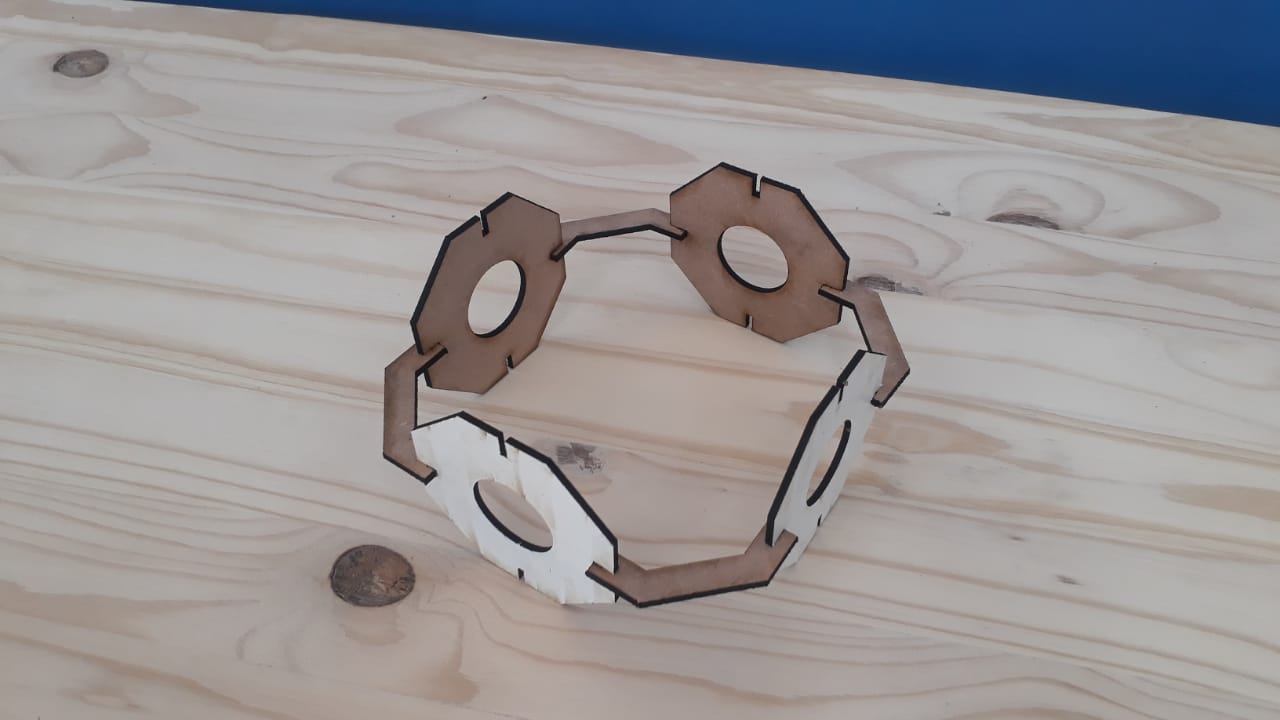
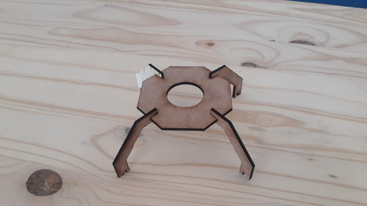
After all pieces cut, then I assembled based on the design.
- Software Used Software like Adobe Illustrator, CorelDRAW, Inkscape.
- Vector Design The design must be in vector format (e.g., SVG, DXF) because the vinyl cutter reads paths and outlines, not pixels. The images can also be imported into vinyl cutter or plotter software for cutting.
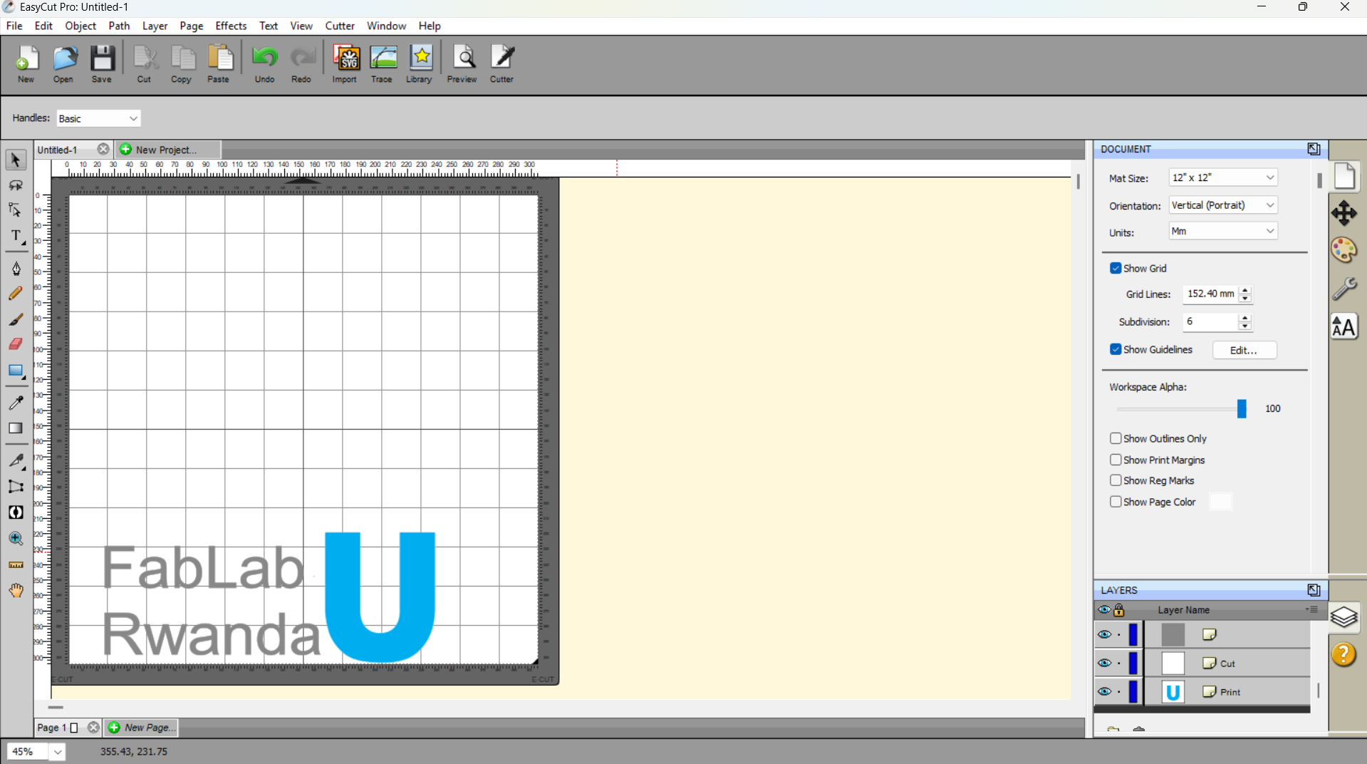
- To prepare the design I have used EasyCut software where I imported the image from the local files, and added text to the part of the design.

- Types of Vinyl
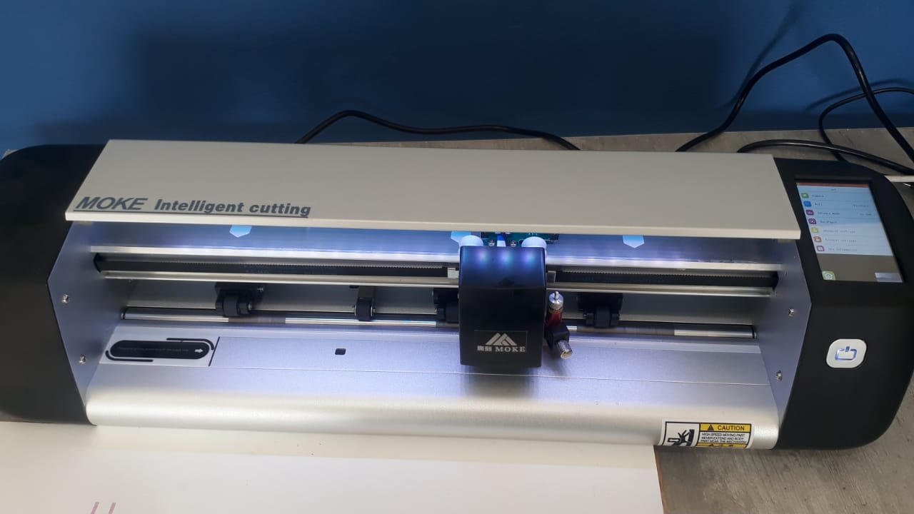
- Adhesive Vinyl -For stickers, wall art, signs. For this project I have used Moke Intelligent cutting and the EasyCut software. I have used adhesive permanent vinyl paper.
- Heat Transfer Vinyl (HTV): For fabrics and garments.
- Loading The vinyl is placed into the cutter, either with or without a cutting mat, depending on machine and material type. Here the vinyl paper was palced without cutting mat.
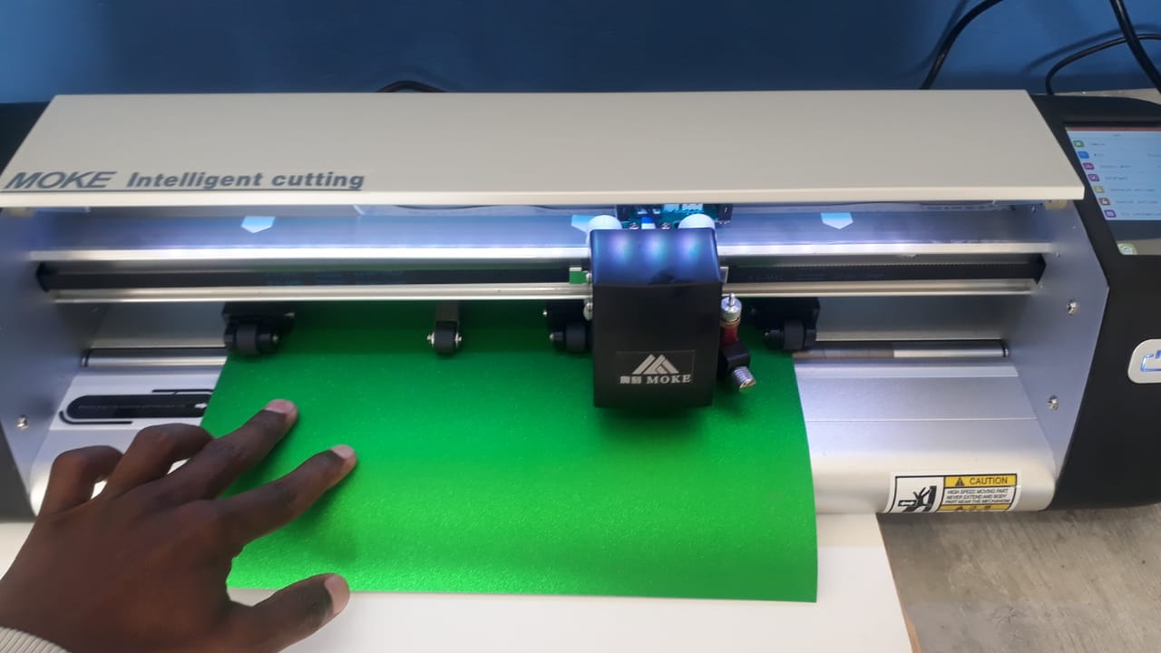
- Vinyl Cutter The machine uses a small blade to follow the vector paths and cut through the vinyl, not the backing sheet.
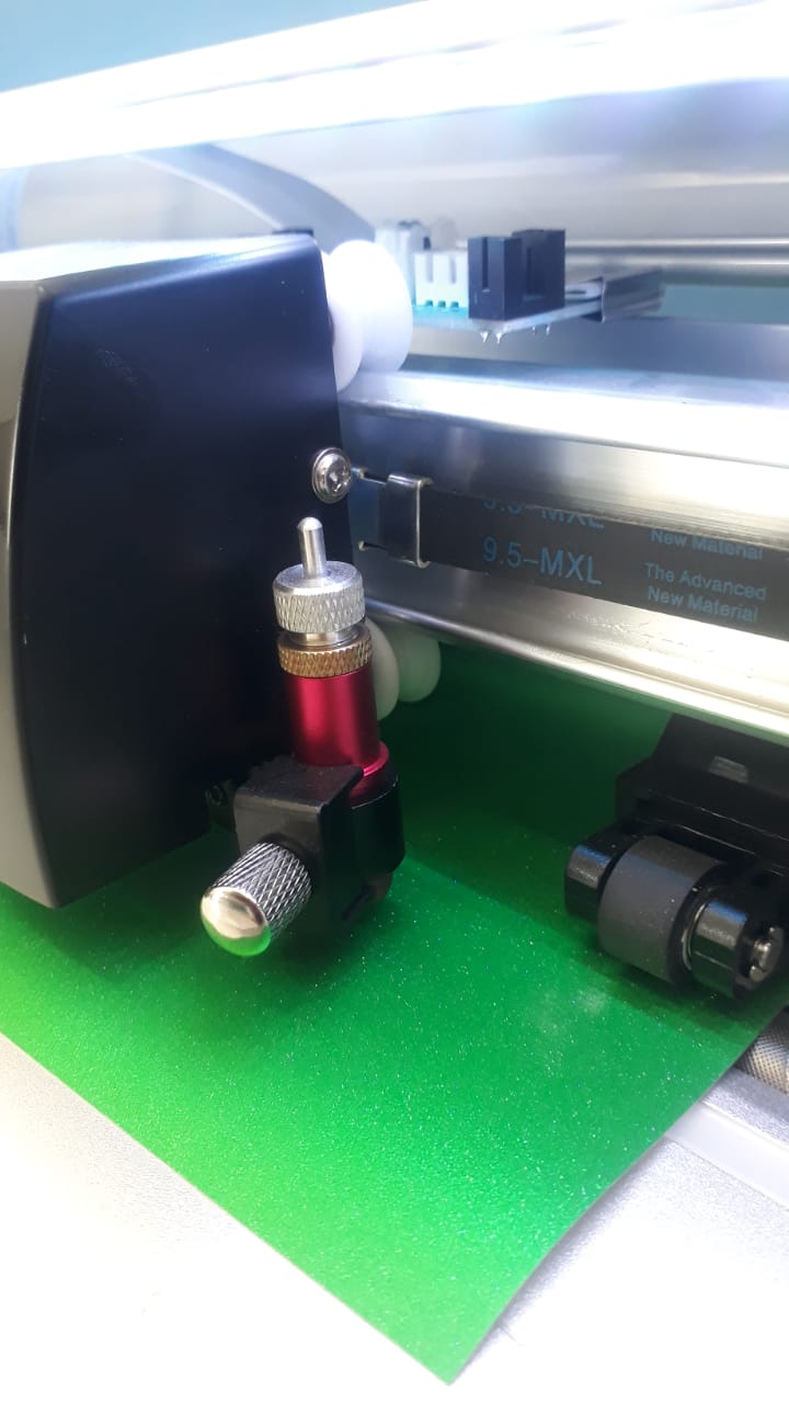
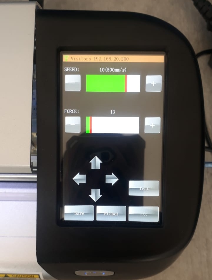
- Settings Adjustments are made for blade depth, speed, and pressure depending on
- Vinyl thickness
- Complexity of the design
- Type of vinyl used
- Weeding The process of removing the excess vinyl (negative space) around the design, using tools like
- Weeding hooks
- Tweezers
- knife
- For the design I used tweezer to remove excess vinyl.
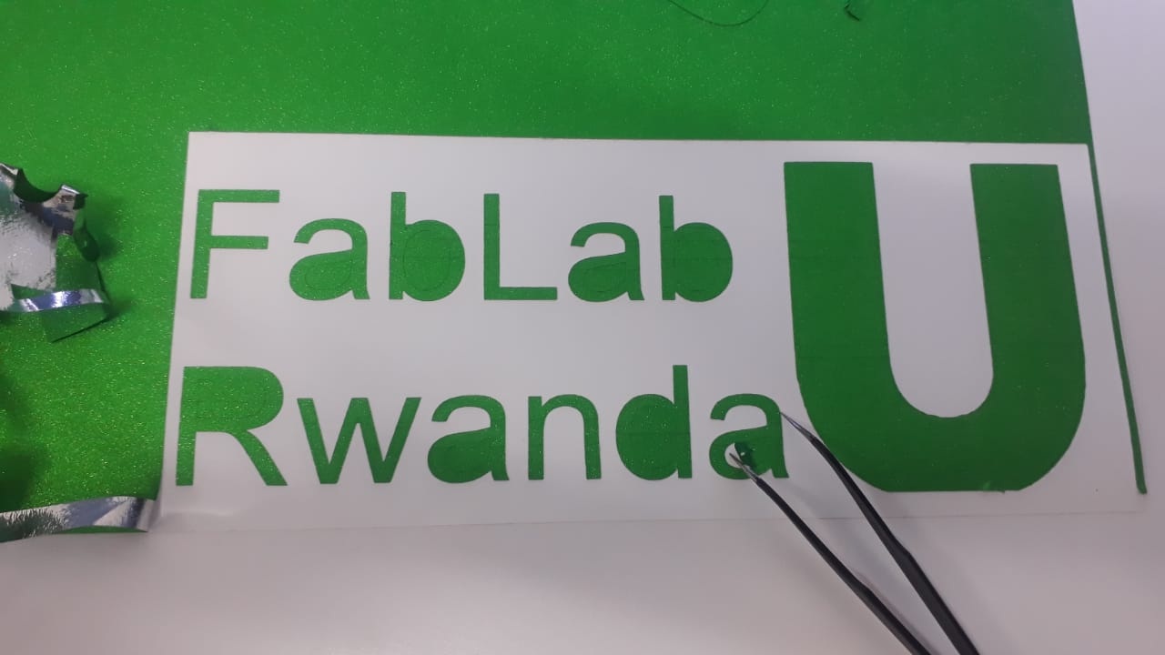
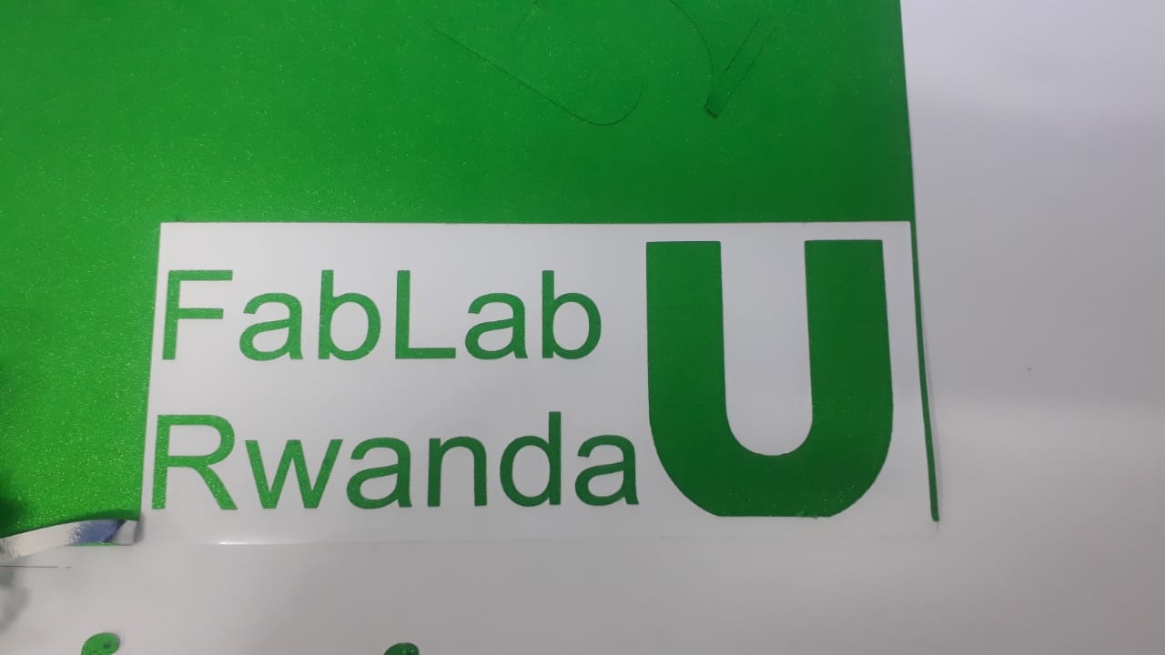
- This reveals the final design, which is left on the backing sheet.
- Adhesive Vinyl
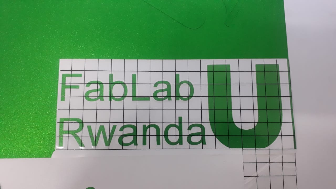
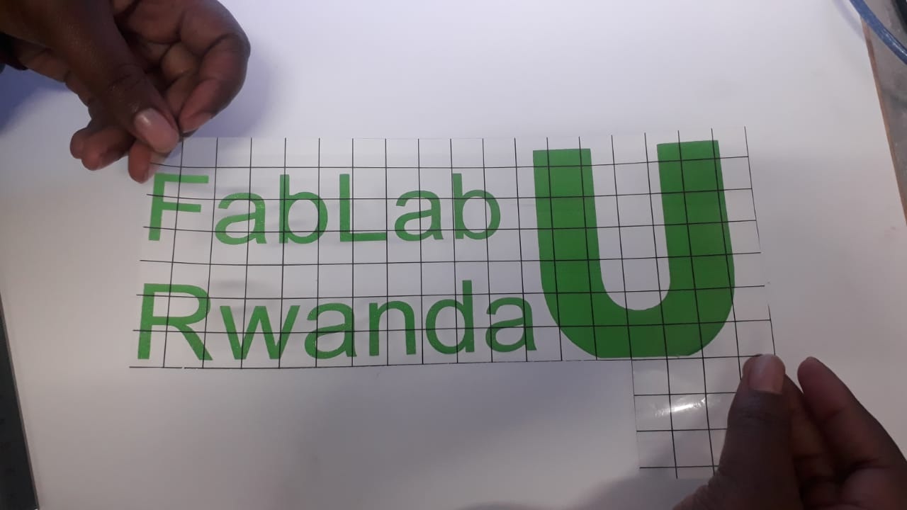
- Apply transfer tape to pick up the weeded design from the cut vinyl paper.
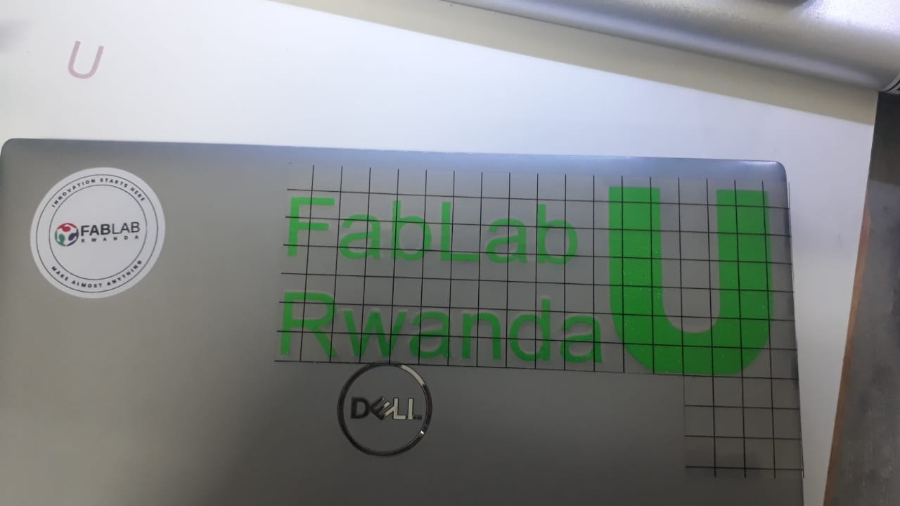
- Transfer it onto the final surface where the design is intended to be placed, then peel off the transfer tape.
- The design after transfer

Vinyl Cutting Process
Vinyl cutting is a process used to cut shapes, letters, or designs from sheets of adhesive vinyl using a computer-controlled machine called a vinyl cutter or plotter. It's widely used in sign-making, custom apparel, stickers, and decals. Vinyl cutting process include;
1. Design PreparationDesign files
SolidWorks design file for part 1SolidWorks design file for part 2
SolidWorks design file for assemble 1
SolidWorks design file for assemble 2
SolidWorks design file for assemble 3
SolidWorks dxf file
RD works design file